

MFJ MFJ-653 User Manual
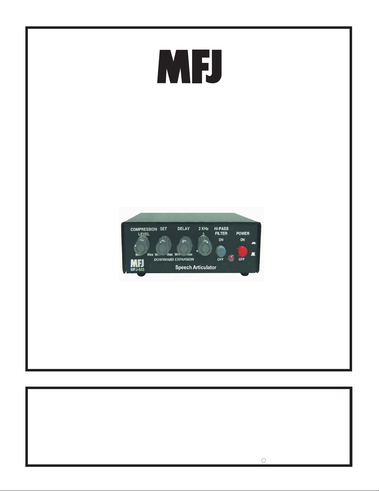
Speech Articulator
Model MFJ-653
VERSION 0A
INSTRUCTION MANUAL
CAUTION: Read All Instructions Before Operating Equipment
MFJ ENTERPRISES, INC.
300 Industrial Park Road
Starkville, MS 39759 USA
Tel: 662-323-5869 Fax: 662-323-6551
COPYRIGHT 2003 MFJ ENTERPRISES, INC.
C

MFJ-653 Speech Articulator Instruction & Technical Manual
TABLE OF CONTENTS
TOPIC PAGE
1. TABLE OF CONTENTS 2
2. LIST OF FIGURES AND TABLES 2
3. INTRODUCTION AND FEATURES 3
4. TYPICAL SPECIFICATIONS 4
5. SYSTEM CONTROLS AND INDICATORS 5
6. SYSTEM SETUP 7
a. INTERNAL HEADERS 7
b. INTERNAL JUMPER BLOCKS 8
c. CABLES 16
d. POWER 16
7. THEORY OF OPERATION 17
8. MFJ-653 EASY-START INSTRUCTIONS 19
9. IN CASE OF DIFFICULTY 20
10.TECHNICAL ASSISTANCE 20
LIST OF FIGURES
Figure 1 Front Panel Jacks and Controls 5
Figure 2 Rear Panel Jacks and Controls 6
Figure 3 Internal Headers 7
Figure 4-11 Internal Jumper Blocks 8-12
Figure 12 Yaesu Mic Jack Pinout, Front View 13
Figure 13 Functional Diagram 17
Figure 14 Compression and Gating Characteristics 18
Figure 15 Block Diagram 18
Figure 16 Gain Control Locations 19
Figure 17 Schematic Diagram 22
LIST OF TABLES
Table 1 Sample Jumper Settings Table for Yaesu FT-1000 Series 13
Table 2 Microphone Pinout 15
2

MFJ-653 Speech Articulator Instruction & Technical Manual
INTRODUCTION & FEATURES
INTRODUCTION
The MFJ-653 hamProAudio Speech Articulator was designed with the serious
operator in mind. Based on the Broadcast Industry Standard Speech
Compression IC the SSM-2166 from Analog Devices it allows the operator
flexibility in the use of input sources and output methods.
The Equalizer was designed to use the most desired center frequency and “Q”
possible.
FEATURES
Choice of 3 Input Sources: In order to add versatility MFJ has included the
following input sources for the MFJ-653:
1. A standard RJ-45 input jack common to most new radios.
2. Standard 8 pin round chassis connector for the majority of the radios
produced in the last 25 years.
3. MFJ’s own input consisting of a 3.5 –mm jack that allows the user to
choose from feeding audio for use with the Heil series of Boom-Mic
Headsets, or even provides phantom voltage on the tip for the MFJ-393
Boom-Mic Headphones or on the ring for use with a computer Boom-Mic
or Boom-Mic headset.
.
Fully Adjustable Gain Amplifier: You have control of the output level to bring
weak microphones up to a useful level.
Wide Range Compression Settings: With an adjustable compression setting
from 1:1 to 15:1 you control the amount of compression to get your signal
thought the toughest of band conditions.
Adjustable Downward Expansion Level and Delay: No more feeding the
background noise into your signal. The MFJ-653 allows you to set the level of
Downward Expansion to only pass audio when you are talking and a delay to
minimize the cutting in and out between words.
Single Equalizer Stage: You have full control of your audio with up to ±16dB of
control centered at 2 Khz.
Switchable High Pass Filter: For that added punch when you need it. Set at 1
Khz.
3

MFJ-653 Speech Articulator Instruction & Technical Manual
INTRODUCTION & FEATURES
By-pass Function: Switch the MFJ-653 in or out. Useful when you want to
Ragchew and don’t need the Compression or Downward Expansion of the MFJ-
653.
Multiple Inputs: The MFJ-653 has multiple inputs for various mics. Your choice
of 8-pin round, RJ-45 or 3.5MM.
Rugged Construction: Attractive all-metal cabinet, conservative component
selection, space age SMD Circuitry and extensive RF filtering ensure solid
performance for years to come. Fully covered by MFJ’s “No Matter What” one
year limited warranty.
Before attempting to operate your MFJ-653, please read the manual thoroughly.
It contains important detail about setting up your unit to obtain the best
performance.
TYPICAL SPECIFICATIONS
Input source……………………Dynamic or electret microphone low or high Z
Output ………………………….High or low Z. Adjustable signal level
Bandwidth …………………….20 kHz
Total harmonic distortion ….1% maximum, <0.2% typical.
4
MFJ-653 Speech Articulator Instruction & Technical Manual
SYSTEM CONTROLS AND INDICATORS
MFJ-653 CONTROLS AND INDICATORS
FRONT PANEL
1 2 3 4 5 6 7
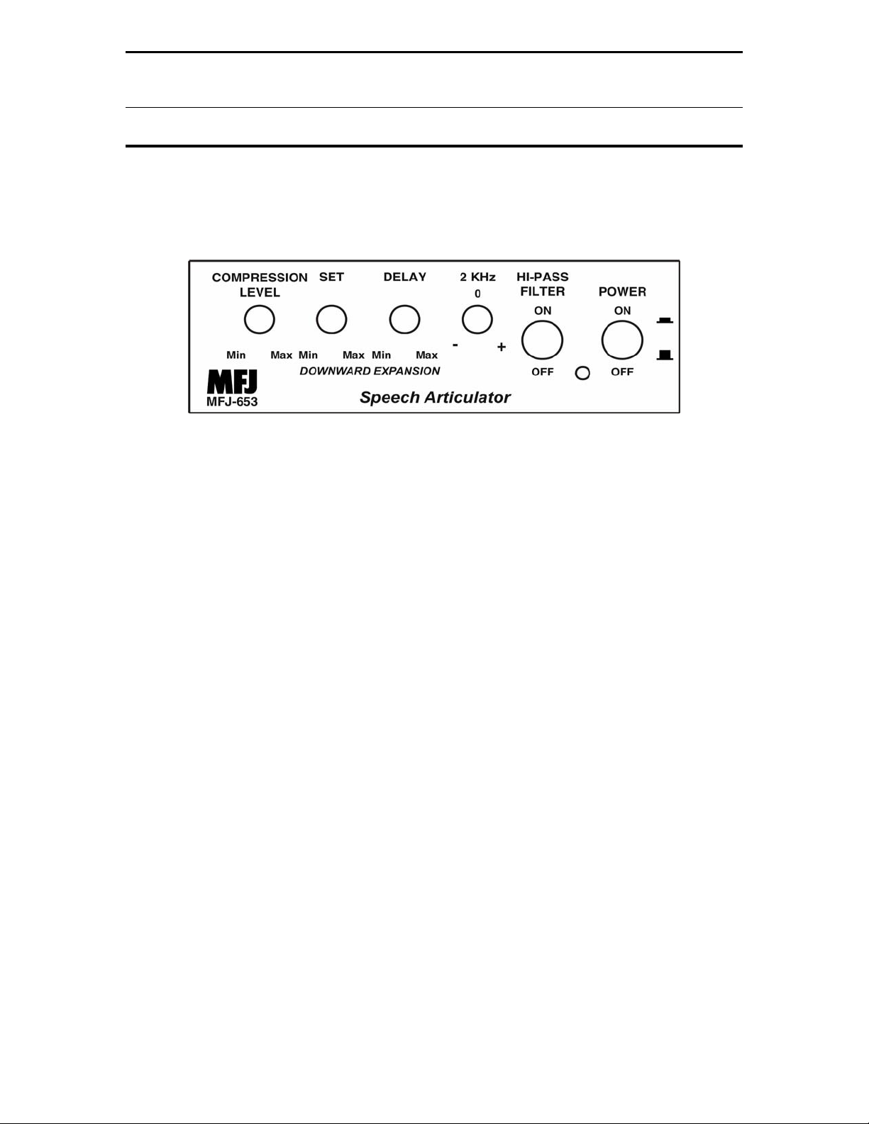
Figure 1: MFJ-653 Front Panel Jacks and Controls
1. Compression Level Set: Controls the Compression function from no
Compression to 15:1 maximum Compression.
2. Downward Expansion Level Set: Allows adjustment of the required
audio level to allow the unit to pass audio. Great for noisy conditions.
3. Downward Expansion Delay Set: Sets the amount of time that the
internal amplifier will remain open with no audio. Great to hold the audio
open between syllables and words.
4. 2 KHZ Boost/Cut: Sets the level of the single equalization stage.
5. 1 KHZ High Pass In/Out: Switches the Butterworth High Pass filter in
and out.
6. Power On LED: Instant visual identification if you are using the MFJ-653
or just the standard microphone.
7. Power ON & OFF/Bypass: Allows you to either use your Microphone
direct or through the MFJ-653.
5
MFJ-653 Speech Articulator Instruction & Technical Manual
REAR PANEL
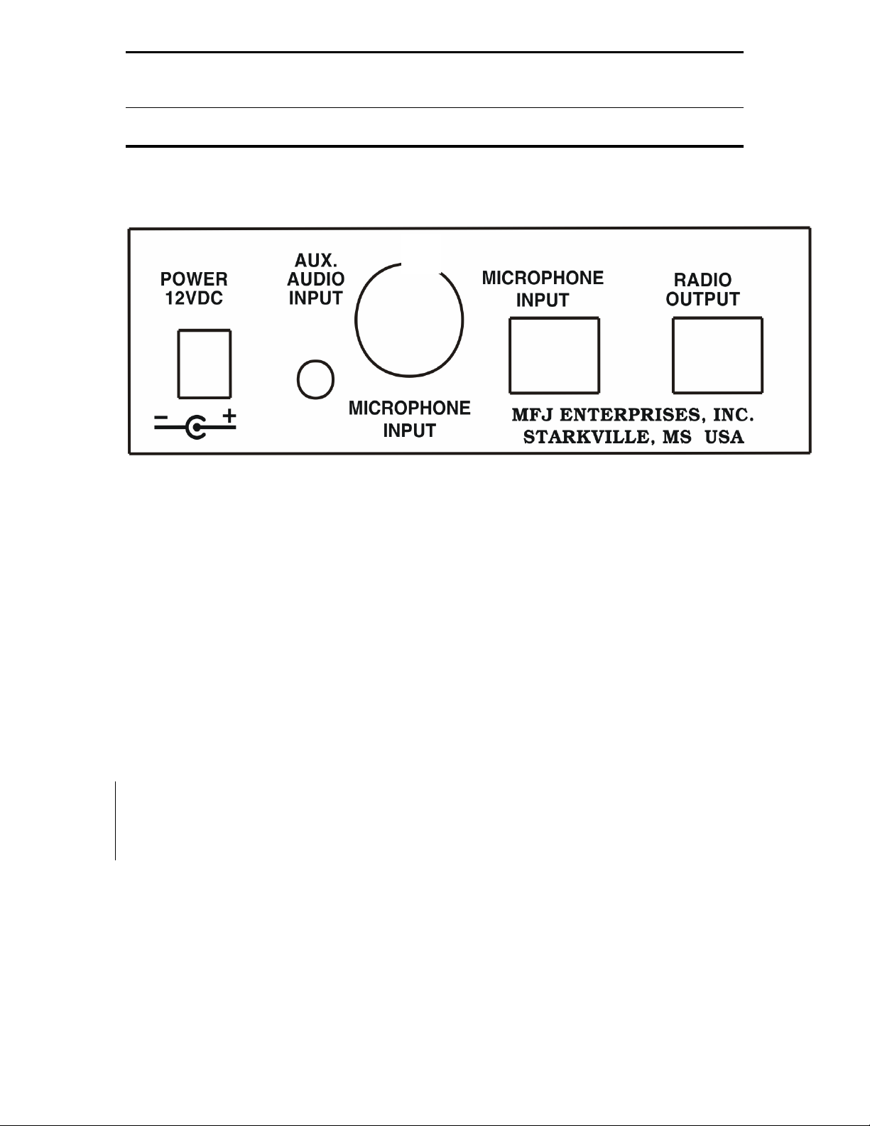
SYSTEM CONTROLS AND INDICATORS
1. Power: Accepts 2.1 –mm power plug to supply 12-15 Vdc to the unit.
2. Auxiliary Input: This 3.5 -mm multifunction input allows just about
anything to be used with the MFJ-653 by setting the appropriate input
jumpers.
3. 8 pin round Input: Allow connection of a 8 pin round Microphone.
4. RJ-45 Input: Allows direct connection of a RJ-45 Microphone.
5. RJ-45 Output: This is where the MFJ-5398 or the MFJ-5397MX is
attached.
Figure 2: MFJ-653 Rear Panel Jacks and Controls
6
MFJ-653 Speech Articulator Instruction & Technical Manual
SYSTEM SETUP
INTERNAL HEADERS
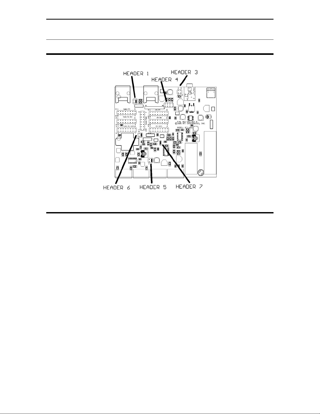
Figure 3: MFJ-653 Internal Headers
1. Header 1: This sets the input of the unit to your specific microphone.
Default 3-4 is set to 680 ohms the standard impedance setting for most
stock microphones. If you need low impedance then move the jumper to
positions 1-2. Remove for high impedance microphones.
2. Header 3: This header allows the phantom voltage set by header 4 to be
passed to the tip or the ring of the Auxiliary input jack. Default is off. If
placed to the tip position it allows the voltage to be placed on the
Microphone Audio line. Pins 1-2 place it on the Ring and 3-4 place it on
the tip and on the Mic line. MOST ICOM MICS REQUIRE THIS
VOLTAGE.
3. Header 4: This header allows phantom voltage to be fed to electret
microphones Default is 0 volts pins 1-2 shorted. Move this jumper to pins
3-4 for 1.5 volts, 5-6 for 5 volts or 7-8 for 8 volts. MOST ICOM MICS
REQUIRE 8 VOLTS.
4. Header 5: This header allows the transformer to be bypassed to increase
the low frequency response. Default is 3-4 bypassed.
5. Header 6: This header allows the transformer to be bypassed to increase
the low frequency response. Default is 3-4 bypassed.
6. Header 7: This header grounds the Mic Ground to the radio and must be
shorted if the transformer is being bypassed. Default is on.
7
MFJ-653 Speech Articulator Instruction & Technical Manual
SYSTEM SETUP
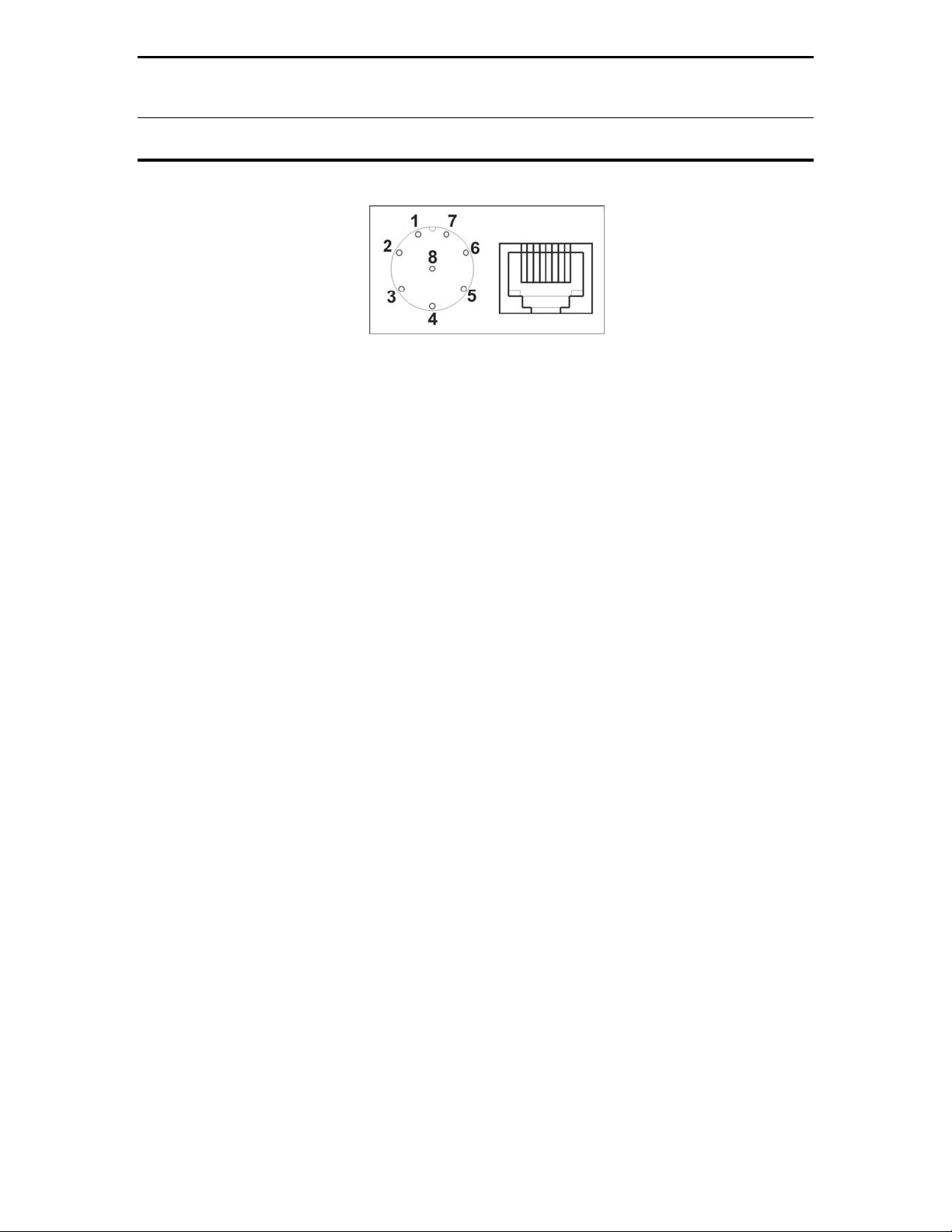
87654321 Yeasu “A”
12345678
ICOM/Kenwood “B”
Figure 4: Rear panel view of Mic Jacks.
Refer to this drawing for the numbering of the headers from 1 to 8. The RJ-45 is numbered with
the clip down. Note the position of the key for the 8 pin round connector. This position may be
different on your particular unit. The round connector follows the A row of jumper numbering.
Also note the view of the RJ-45 jack. The RJ-45 connector is numbered differently by different
radio vendors. The numbering follows the “A” jumper numbering for Yaesu, and the B row of
Jumper numbering for ICOM and Kenwood. Just to be sure, map the actual pin function – not
the pin number – of your radio’s mic connector to the numbered pins shown above so as to
determine the correct jumper positions to use in the MFJ-653.
INTERNAL JUMPER BLOCKS
The Jumper Installation diagrams within this instruction manual will help you in
setting up your MFJ-653 to match your radio. If your radio is not listed with the
diagram, it means that we have not verified your radio to use that diagram. You
can try to install jumpers as indicated. If that does not work, please refer to the
radio manual to identify the MIC pin assignment for you radio then follow the
instructions given at the end of this section in the MFJ-653 instruction manual to
install the jumpers.
8
 Loading...