

MFJ MFJ-652 Instruction Manual
Model MFJ-652
CAUTION: Read All Instructions Before Operating Equipment
MFJ ENTERPRISES, INC.
Tel: 662-323-5869 Fax: 662-323-6551
VERSION 1A
INSTRUCTION MANUAL
300 Industrial Park Road
Starkville, MS 39759 USA
COPYRIGHT 2005 MFJ ENTERPRISES, INC.
C

DISCLAIMER
Information in this manual is designed for user purposes only and is not
intended to supersede information contained in customer regulations, technical
manuals/documents, positional handbooks, or other official publications. The
copy of this manual provided to the customer will not be updated to reflect
current data.
Customers using this manual should report errors or omissions,
recommendations for improvements, or other comments to MFJ Enterprises, 300
Industrial Park Road, Starkville, MS 39759. Phone: (662) 323-5869; FAX: (662)
323-6551. Business hours: M-F 8-4:30 CST.

MFJ-652 hamProAudio
TM
Transmit Audio Equalizer Instruction & Technical Manual
TABLE OF CONTENTS
TOPIC PAGE
1. TABLE OF CONTENTS 2
2. LIST OF FIGURES 2
3. INTRODUCTION AND FEATURES 3
4. TYPICAL SPECIFICATIONS 4
5. SYSTEM CONTROLS 5
a. FRONT PANEL JACKS AND CONTROLS 5
b. REAR PANEL JACKS AND CONTROLS 6
6. SYSTEM SETUP 7
a. INTERNAL HEADERS 7
b. INTERNAL JUMPER BLOCK 8
c. CABLES 10
d. POWER 10
e. HEADPHONES 10
f. RADIO AUDIO 10
7. THEORY OF OPERATION 11
8. MFJ-652 EASY-START INSTRUCTIONS 12
9. IN CASE OF DIFFICULTY 15
10.TECHNICAL ASSISTANCE 15
LIST OF FIGURES
Figure 1 Front Panel Jacks and Controls 5
Figure 2 Rear Panel Jacks and Controls 6
Figure 3 Internal Headers 7
Figure 4-10 Internal Jumper Blocks 8-12
Figure 11 Functional Diagram 15
Figure 12 Schematic 20
LIST OF TABLES
Table 1 Microphone Pinout 13
- 2 -

MFJ-652 hamProAudio
TM
Transmit Audio Equalizer Instruction & Technical Manual
INTRODUCTION & FEATURES
INTRODUCTION
The MFJ-652 hamProAudio Transmit Audio Equalizer is a quality microphone
audio equalizer. With 4 adjustable center frequencies you can adjust your
microphone audio for rich full audio for rag chewing. For serious DXing you can
increase the high and decrease the lows for a signal that really punches through
the pile-ups.
hamProAudio Quality: Designed with the serious ham in mind. Not just a
typical audio equalizer being used with an amateur station. Choice of
components and extensive RF filtering and bypassing allows for a unit that is
designed to be used in a RF environment.
Fully adjustable Gain Amplifiers: You have full control of the input level from
your microphone and output level to your radio. With MFJ’s LED monitoring you
set the output level once and then feel confident that you are driving your radio
with the perfect level no matter how much you increase or decrease the gain of
each section of the equalizer.
Audio Pass Through from your Radio: No need to switch the headphones
from the MFJ-652 to the radio. At the push of a button you can instantly switch
from normal operation to a test mode. This allows you to adjust the settings
without going on the air with the built in monitor amplifier.
By-pass Function: Switch the MFJ-652 in or out and you still have the received
audio in the headphones.
Multiple Outputs: The MFJ-652 has multiple audio outputs. Microphone audio
is fed out through the RJ-45 connector or through the 3.5 -mm Auxiliary Output
Jack.
Rugged Construction: Attractive all-metal cabinet, conservative component
selection, space age SMD Circuitry and extensive RF filtering ensure solid
performance for years to come. Fully covered by MFJ’s “No Matter What” one
year limited warranty.
Before attempting to operate your MFJ-652, please read the manual thoroughly.
It contains important details about setting up your unit to obtain the best
performance.
- 3 -

MFJ-652 hamProAudio
TM
Transmit Audio Equalizer Instruction & Technical Manual
INTRODUCTION & FEATURES
TYPICAL SPECIFICATIONS
Input source……………………Dynamic or Electret mic low or high Z
Stereo or Monaural radio audio.
Sound card or Modem
Output ………………………….Adjustable signal level. RJ-45 or 3.5 –mm
Frequency Range……………..300, 600, 1200, 2400 Hz center
Overall Response……………..100-5000 Hz
Total harmonic distortion …….1% maximum, <0.2% typical
- 4 -
MFJ-652 hamProAudio
TM
Transmit Audio Equalizer Instruction & Technical Manual
SYSTEM CONTROLS
MFJ-652 JACKS AND CONTROLS
MFJ Voice Band Microphone EqualizerhamProAudio™
0 0 0 0
2400 Hz1200 Hz600 Hz300 Hz
MONITOR
OUTPUT
MFJ-652
EQUALIZER
ON
MIC IN
-
+
-
+
-
+
-
+
INPUT LEVE L POWER OUTPUT LEVEL
Max Min Max Min
1 2 3 4 5 6 7
9
8 10 11
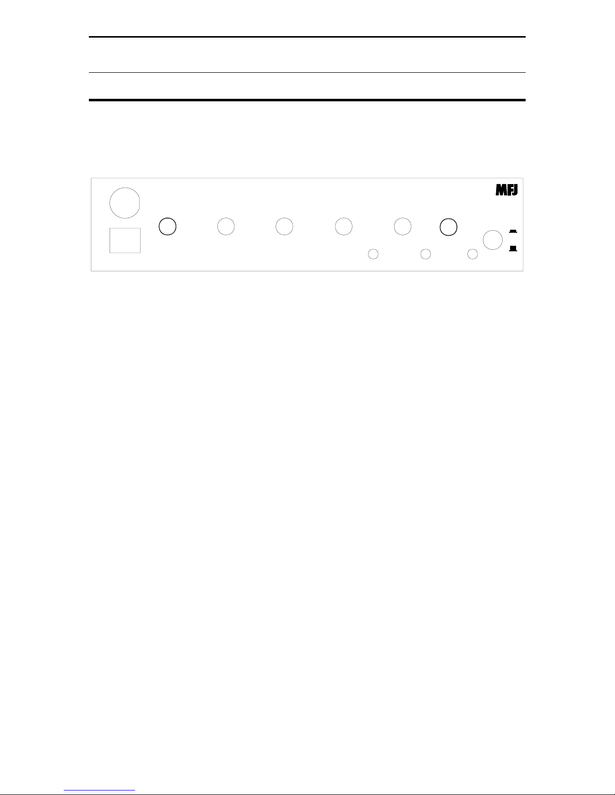
Figure 1: MFJ-652 Front Panel Jacks and Controls
1. RJ-45 Microphone Input Jack: Accepts input from a Standard RJ-45
microphone.
8-Pin Microphone Input Jack: Accepts input from a standard 8 pin
microphone.
2. 300 Hz: Cuts or emphasizes lowest speech frequencies.
3. 600 Hz: Cuts or emphasizes mid-range speech frequencies.
4. 1200 Hz: Cuts or emphasizes upper-range speech frequencies.
5. 2400 Hz: Cuts or emphasizes syllabant sounds and adjacent channel
“chatter”.
6. Input Level LED: Allows for easy setting of the input level to the
equalizer. Never worry about overdriving the equalizer.
7. Monitor Output Level: Easily set the output monitor to a comfortable
level in the headphones.
8. Output Level LED: Set the output level trimpot one time and you will
have easy control of the signal sent to your radio.
9. Output Level Control: Adjusts the level sent to you radio.
10. Power LED: Visual indication whether the unit is in line or not.
11. On & Off/Bypass Switch: Allows you to use either your microphone
direct or through the MFJ-652.
OFF/
BYPASS
- 5 -
MFJ-652 hamProAudio
POWER
12VDC
FROM
RADIO
TM
Transmit Audio Equalizer Instruction & Technical Manual
SYSTEM CONTROLS
MFJ ENTERPRISES, INC.
STARK VIL LE, MS USA
HEADPHONE
AUDIO
OUT
EXTERNAL
PTT
SWITCH
AUX.
AUDIO
OUTPUT
AUX.
AUDIO
INPUT
MIC
OUT
RECEIVED
AUDIO
INPUT
OUTPUT
LED
LEVEL
FROM
MFJ-652
INPUT
LED
LEVEL
1 2 3 4 5 6 7 9 8 10
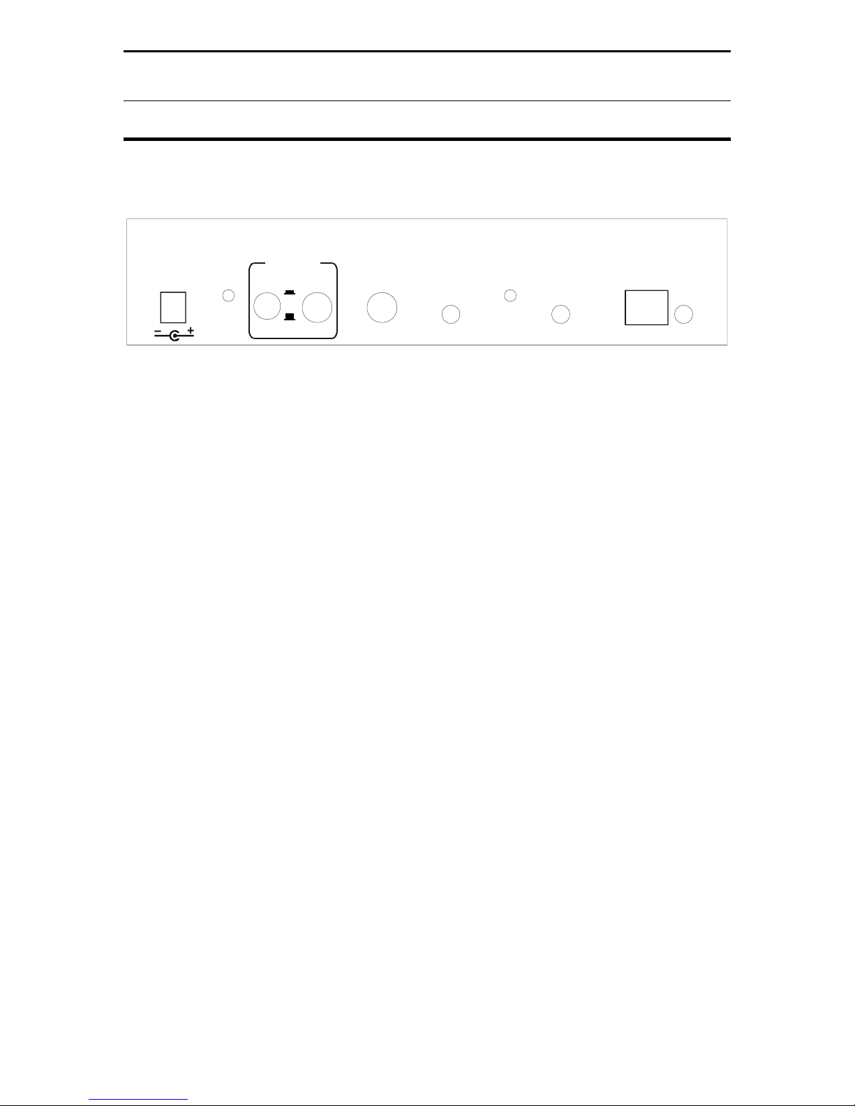
Figure 2: MFJ-652 Rear Panel Jacks and Controls
1. Power: Accepts 2.1 –mm power plug to supply 12-15 volts to the unit.
2. Output LED Level adjust: Sets the level at which the output led
illuminates.
3. From Radio/From MFJ-652: This switch allows the audio to be fed from
the radio to the headphones or in the test mode for the audio from the
microphone to be fed to the headphones for setting the MFJ-652.
Additionally in the test mode the PTT is disabled allowing you to key the
microphone without keying the radio.
4. Headphones Out: Allows you to use a pair of ¼ stereo headphones.
5. External PTT Input: Accepts a ¼ inch plug from a remote hand switch or
foot switch
6. Auxiliary Output: Accept a 3.5 –mm plug for direct audio output. With
internal jumper set allows PTT also.
7. Input LED Level: Allows for adjustment of the input gain depending on
your microphone.
8. Auxiliary Input: This multifunction input allows for just about anything to
be used with the MFJ-652. Use a Heil boom mic, The MFJ-393 Boom Mic
Headset or even a computer microphone by setting the appropriate
internal jumper.
9. RJ-45 Mic Output: This is where the MFJ-5398 or MFJ-5397MX is
attached.
10. Received Audio Input: This jack allows either stereo or mono (if wired
properly) audio from your radio.
- 6 -

MFJ-652 hamProAudio
TM
Transmit Audio Equalizer Instruction & Technical Manual
INTERNAL HEADERS
SYSTEM SETUP
Figure 3: MFJ-652 Internal Headers
1. Header 1: This sets the input of the unit to your specific microphone.
Default 1-2 is set to 500-1000 ohms, the standard impedance setting for
most stock microphones. If you need low impedance then move the
jumper to positions 3-4. Remove for high impedance microphones.
2. Header 2: This allows the PTT line to be placed on the ring of the 3.5 –
mm auxiliary input jack. Default is off.
3. Header 3: This header allows phantom voltage to be fed to electret
microphones Default is 0 volts pins 1-2 shorted. Move this jumper to pins
3-4 for 1.5 volts, 5-6 for 5 volts or 7-8 for 8 volts.
4. Header 4: This header allows the phantom voltage set by header 4 to be
passed to the ring of the Auxiliary input jack. Default is off. If used with
standard computer microphone/headphones set to 5 volts.
5. Header 5: This header allows the PTT to be placed on the ring of the 3.5
-mm Auxiliary Output Jack.
6. Header 6: This header places phantom voltage on the microphone input
line and must be shorted for use with microphones that require phantom
voltage.
- 7 -
 Loading...