

Model MFJ-644
VERSION 1A
INSTRUCTION MANUAL
CAUTION: Read All Instructions Before Operating Equipment
MFJ ENTERPRISES, INC.
300 Industrial Park Road
Starkville, MS 39759 USA
Tel: 662-323-5869 Fax: 662-323-6551
COPYRIGHT 2007 MFJ ENTERPRISES, INC.
C

TABLE OF CONTENTS
TOPIC PAGE
1. TABLE OF CONTENTS 2
2. LIST OF FIGURES AND TABLES 2
3. INTRODUCTION AND FEATURES 3
4. SYSTEM CONTROLS AND INDICATORS 4
5. SYSTEM SETUP 6
a. INTERNAL HEADERS 6
b. INTERNAL JUMPER BLOCKS 7
c. CABLES 13
d. POWER 13
e. HEADPHONES 14
f. RADIO AUDIO 14
7. THEORY OF OPERATION 14
8. MFJ-644 EASY-START INSTRUCTIONS 15
9. IN CASE OF DIFFICULTY 18
10.TECHNICAL ASSISTANCE 18
LIST OF FIGURES
Figure 1 Front Panel Jacks and Controls 4
Figure 2 Rear Panel Jacks and Controls 5
Figure 3 Internal Headers 6
Figure 4-10 Internal Jumper Blocks 7-11
Figure 11 Yaesu Mic Jack Pinout, Front View 12
Figure 12 Block Diagram 15
Figure 13 Schematic 17
LIST OF TABLES
Table 1 Sample Jumper Settings Table for Yaesu FT-1000 Series 12
Table 2 Microphone Pinout 13

________________________________________________________________
MFJ-644 Universal SO2R Switch Instruction and Technical Manual
INTRODUCTION & FEATURES
INTRODUCTION:
The MFJ-644 hamProAudio Universal SO2R Switch is a quality Single Operator 2
Radio Switch. With the ability to switch the microphone audio between 2 radios and full
control of the audio from both radios, you will have the ultimate SO2R switch at a great
value.
hamProAudio Quality: Designed with the serious ham in mind. Choice of components
and extensive RF filtering and bypassing allows for a unit designed for an RF
environment.
Designed for ease of use: Set the internal jumpers for the MFJ-393 Professional BoomMic Headphones, The Heil Pro Set series of Boom-Mic Headsets or even a Computer
Boom-Mic Headset.
Instant visual indication of transmit audio path: With wide spaced LED indicators
you instantly know which radio your audio is being passed to.
Choice of PTT function: Use your microphone PTT switch, a foot or hand switch, or
the convenient PTT switch located on the front of the MFJ-644.
Full control of audio output: With Mix, Radio 1, Stereo, or Radio 2 in the headphones
you can instantly select how you want to hear the audio in the headphones.
Full control of accessories: Additional inputs and dual outputs for your keyer and 2
lines to control anything you want or need to switch an antenna between radios or key an
amplifier.
Rugged Construction: Attractive all-metal cabinet, conservative component selection
and extensive RF filtering ensure solid performance for years to come. Fully covered by
MFJ’s “No Matter What” one year limited warranty.
IMPORTANT: Before attempting to operate your MFJ-644, please read the
manual thoroughly. It contains important detail about setting up your unit to
obtain the best performance.
3
________________________________________________________________
MFJ-644 Universal SO2R Switch Instruction and Technical Manual
SYSTEM CONTROLS AND INDICATORS
Front Panel Jack and Controls
™
RADIO 1
MIC
INPUT
RADIO 1
POWER
ON
OFF
HEADPHONES
MIC
INPUT
HEADPHONE AUDIO
MIX
BOTH
MIX
MIC TO
RADIO
2
1
MFJ-644
RADIO 2
STEREO
RADIO 2
PTT
LOCK
RADIO 2RADIO 1
UNLOCK
1 2 3 4 5 6 7 8 9 10 11 12
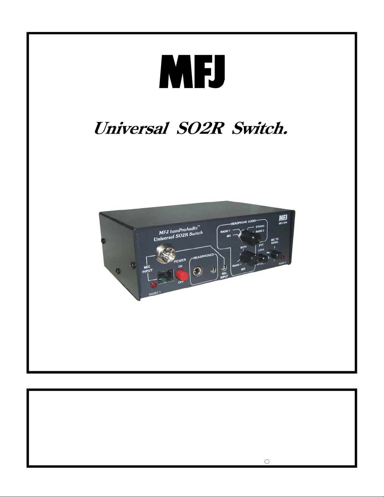
Figure 1: MFJ-644 Front Panel Jacks and Controls
1. Radio 1 LED Indicator: Indicates Radio 1 is selected for microphone audio.
2. RJ-45 Microphone Input Jack: Accepts input from a standard RJ-45 Microphone.
3. 8-Pin Microphone Input Jack: Accepts input from a standard 8 pin round
microphone.
4. Power Switch: Turns the unit on or off.
5. ¼ Inch headphone Jack: Stereo jack to hook up a standard set of ¼ inch stereo
headphones.
6. 3.5 –mm stereo headphone jack: Stereo jack to hook up a pair of quality stereo
3.5–mm headphones.
7. 3.5 –mm microphone input connector. Microphone input. Phantom voltage is also
available on the either the tip or ring for your specific need.
8. Mix Control: Control the audio from either radio from Radio 1 only to Radio 2 only
and everything in between when in the Mix position.
9. Audio selection switch: Choose from Mix, Radio 1, Stereo or Radio 2 audio.
10. PTT: Use this locking switch to key the radio.
11. Radio 1/ Radio 2-selection switch: This switches between Radio 1 and Radio 2.
12. Radio 2 LED indicator: Indicates Radio 2 is selected for microphone audio.
4
________________________________________________________________
MFJ-644 Universal SO2R Switch Instruction and Technical Manual
SYSTEM CONTROLS AND INDICATORS
Rear Panel Jacks
MFJ ENTERPRISES, INC.
STARKVILLE, MS USA
AUX.
AUDIO
INPUT
AUX.
AUDIO
OUTPUT
RADIO2RADIO
1
KEY
INPUT
KEY
OUTPUT
RADIO2RADIO
1
EXTERNAL
PTT
SWITCH
RADIO 2
AUDIO
INPUT
RADIO 2
AUDIO
OUTPUT
RADIO 1
AUDIO
INPUT
RADIO 1
AUDIO
OUTPUT
POWER
12VDC
1 2 3 4 5 6 7 8 9 10 11 12
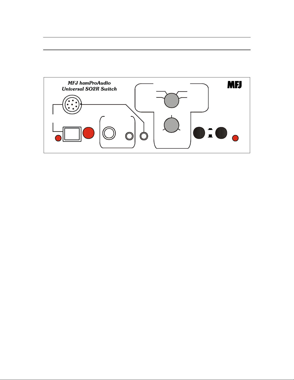
Figure 2: MFJ-644 Rear Panel Jacks
1. Auxiliary Input: This stereo 3.5 –mm jack allows 2 independent lines to be
controlled.
2. Auxiliary Output Radio 2: This stereo 3.5 –mm jack allows the lines to be fed to
radio 2 devices.
3. Auxiliary Output Radio 1: This stereo 3.5 –mm jack allows the lines to be fed to
radio 1 devices.
4. Key/Keyer in: This 3.5 –mm jack allows a key or keyer to be passed through the unit.
Can also be used as an additional auxiliary input.
5. Key/Keyer out Radio 2: This allows the Key or Keyer to be connected to Radio 2.
6. Key/Keyer out Radio 1: This allows the Key or Keyer to be connected to Radio 1.
7. PTT Input: This ¼ inch jack allow a foot or hand switch to be connected to the
MFJ-644.
8. Radio 2 Audio: This 3.5 –mm jack allows audio to be fed from Radio 2.
9. Radio 2 Output: This is where either a MFJ-5398 or MFJ-5397MX connects the unit
to your radio.
10. Radio 1 Audio: This 3.5 –mm jack allows audio to be fed from Radio 1
11. Radio 1 Output: This is where either a MFJ-5398 or MFJ-5397MX connects the
unit to your radio.
12. Power: Accepts 2.1 –mm plug to supply 12-15 Vdc to the MFJ-644.
5

________________________________________________________________
MFJ-644 Universal SO2R Switch Instruction and Technical Manual
SYSTEM SETUP
Internal Headers
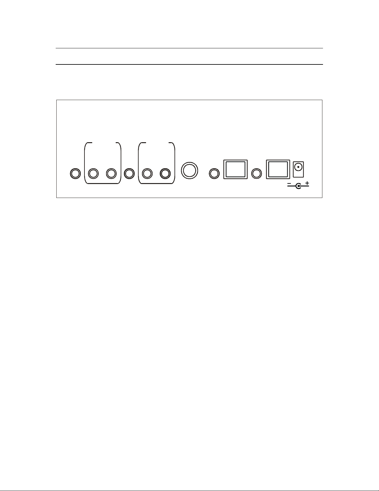
Figure 3: MFJ-644 Internal Headers
1. Header 1: This header allows phantom voltage to be fed to electret microphones
Default is 0 volts pins 1-2 shorted. Move this jumper to pins 3-4 for 1.5 volts, 5-6 for 5
volts or 7-8 for 8 volts. If used with standard computer microphone/headphones set to 5
volts.
2. Header 2: This header allows the phantom voltage set by header 4 to be passed to the
ring or tip of the Auxiliary input jack. Pins 1-2 place the voltage on the tip. Pins 3-4
place the voltage on the ring. Default is off. Pins 1-2 also place the voltage on the
Microphone Input connector and must be shorted for stock microphones that require
phantom voltage.
6
 Loading...