

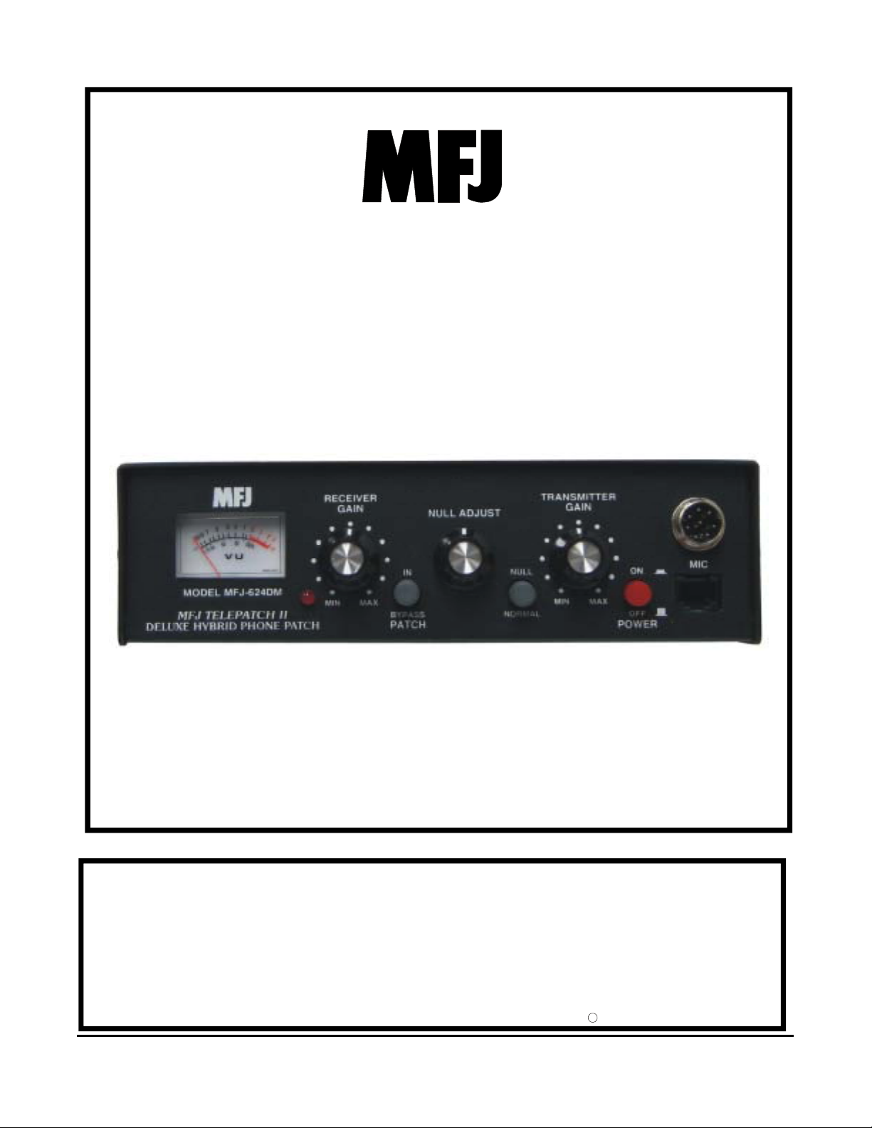
Delux Hybrid Phone Patch
Model MFJ-624DM
INSTRUCTION MANUAL
VERSION 0E
CAUTION: Read All Instructions Before Operating Equipment
MFJ ENTERPRISES, INC.
300 Industrial Park Road
Starkville, MS 39759 USA
Tel: 662-323-5869 Fax: 662-323-6551
COPYRIGHT 2006 MFJ ENTERPRISES, INC.
C

Introduction
Thank you for purchasing the MFJ-624DM Telepatch II. We believe this phone patch with its unique
hybrid design is one of the finest patches on the market today. This patch is designed to provide
undistorted audio and good receiver to transmitter isolation. The adjustable NULL control allows over
30 dB null in most telephones to provide smooth VOX operation.
Please take the time to completely read the instruction manual to get familiar with the MFJ-624DM
before operation, particularly if you have never operated a phone patch before.
Warning: Only one radio should be connected to the radio at any given time. If
more than one radio is connected damage may occur to the unit or to the
transceivers.
Installation
THE MFJ-624DM can me configured for use with a radio having either a 8-pin round connector or an 8pin modular connector. The MFJ-624DM is designed to remain permanently installed between a
transceiver, a telephone line with a modular connector, and a telephone receivers handset. The
telephone and the radio will operate as if the phone patch were not in the circuit when the Patch
IN/BYPASS switch is in the BYPASS (out) position.
1. Connection to Telephone
a. Disconnect the modular phone from its line cord.
b. Connect the line cord from the wall jack to the modular jack on the Telepatch II labeled
Line.
c. Connect a second line cord from the modular jack on the Telepatch II PHONE to your
telephone.
2. Connection to Radio
a. Transceivers with Patch IN/OUT Connectors
i. Connect a shielded audio cable from AUDIO IN on the Telepatch II to PATCH
OUT on the radio.
ii. Connect a shielded audio cable from AUDIO OUT on the Telepatch II to
PATCH IN on the radio.
iii. Connect a microphone to the 8-pin microphone jack on the front panel. Only
one microphone should be connected at any given time.
iv. Connect a speaker to the speaker out jack of the Telepatch II.
b. Radios without PATCH IN/PATCH OUT Connectors
The MFJ-624DM has a modular connector on the rear for connection to a transceiver
microphone jack. If the transceiver has a modular connector a cat 5 patch cable can be used
to connect the transceiver with the MFJ-624DM. If the transeiver has an 8-pin round
connector a cable such as the MFJ-5398 should be used. Use the following section to
conifure the jumpers specific to the transceiver being used.
If your radio is listed in the appendix of this manual you can use the pre-tested jumper
confiuragtions shown. MFJ recommends that you check each connection before applying
power to the MFJ-624DM. If your radio is not listed use the following section to determine
the proper jumper settings.

a. Determine which pins of the micrphone connector (either modular or round) are used
for the Mic Audio and the Mic Ground. The wiring for most radio microphones will
be printed in the radio instruction manual. Write the pin numbers in the following
table for reference. Note, some radios have two ground connections on the
microphone. The ground used for PTT ground should be the one used
Description Radio Pin Number
Mic Audio
Mic Ground
b. Jumper Configuration
The MFJ-624DM must be configured specifically for the transceiver being
connected. The MFJ-624DM comes from the MFJ Factory pre-configured to
operate with the ICOM 706 Series.
a. Remove the cover of the MFJ-624DM by loosening the six screws on each
side of the cover. Be careful not to misplace them. Remove the cover from
the chassis and locate the headers on the right side of the board labeled JMP 1
(MIC GND), JMP2 (MIC AUDIO), JMP3 (THRU PASS), JMP4 (MIC
AUDIO).
b. Remove each of the jumpers on each of the headers. A small pair of needle
nose pliers will make this much easier.
c. Using the Pin numbers previously written in the table above and re-place
jumpers in the following order.
i. JMP4 (Mic Audio), place a single jumper on the number
corosponding to the radio pin number previously recorded above.
Note: Only one jumper should be placed on JMP4 (Mic Audio)
ii. JMP2 (Mic Audio), place a single jumper on the number corosponding
to the radio pin number previously recorded above. This will be the
same as in step I above. Note: Only one jumper should be placed on
JMP2 (Mic Audio).
iii.
1. JMP1 (Mic Gnd), place a single jumper on the number
corresponding to the radio pin number recorded above for
Radio Microphone Ground. Note: Only one jumper should be
placed on JMP4 (Mic Audio).
iv. JMP3(Thru Pass) and JMP , place jumpers on the remaining 7 pins
not used on any pins of JMP4, JMP2, JMP1. These jumpers will allow
the microphone to operate the radio just as it would if plugged directly
into the radio.
c. Connect a shielded audio cable from the headphones, speaker out, or monitor out jack
of the radio to the AUDIO IN jack on the Telepatch II.
i. If your radio has an 8-pin modular connector use a CAT 5 ethernet computer
networking cable, such as the MFJ-5397MX, to connect the mic output jack on
the MFJ-624DM and the mic input jack on the radio. If your radio has an 8-pin
round connector a cable such as the MFJ-5398 should be used.
ii. Connect the microphne suppied with your radio to either the 8-pin modular or 8-
pin round mic input jack of the Telepatch II. Only one microphone should be
connected to the MFJ-624DM.

iii. Connect a speaker to the SPEAKER jack on the MFJ-624DM Telepatch II. This
speaker will allow the station operator to monitor the audio from received
stations and telephone contacts.
c. Jumper Function
Phone Patch
Mic
Output
12
VDC
LinePhn
Phone Jack
Phone
Patch Out
Transceiver
Phone Patch Adjustments
1. Null Adjustment
a. Connect a 12-volt DC power supply or adapter such as the MFJ-1312 to the 2.5mm
(3/32”) power input jack on the rear panel.
b. Turn on the receiver and monitor a QSO in progress. Adjust the receiver volume on
the radio ofr a comfortable listening level.
c. Turn the Power switch on the Telepatch II to ON.
d. Push the NULL switch to NULL (IN).
e. Push the PATCH IN /BYPASS to IN.
f. Turn the RECEIVER GAIN control on the Telepatch II until the VU meter reads
about 100%.
g. Place a call on the telephone to a third party.
h. Adjust the NULL control on the TELEPATCH II for a null reading (lowest reading
on the VU meter).
Audio
Spk
OutIn
Patch In
Mic
Output
Phone Patch
12
VDC
Phone Jack
Phone
LinePhn
Audio
Spk
Ext. Speaker
Transceiver
Mic In
OutIn
i. Set the NULL switch to the NORMAL position.
2. Receiver Gain
a. Adjust the RECEIVER GAIN control on the Telepatch II until the audio level into the
telephone sounds about normal according to the third party to whom you placed the call.
This should occur ON VOICE PEAKS at a level around –10dBm. The meter is
calibrated to read 100% (zero VU) when the actual signal level is –10dBm.
3. Transmitter Gain
a. Set the PATCH IN/BYPASS switch to IN.
b. While the person on the phone speaks, adjust the TRANSMITTER GAIN control on
the Telepatch II for full modulation of the transmitter’s mic audio circuit.Adjust the
VOX gain on your radio so the VOX keys the PTT when the person speaks and
unkeys your radio when he does not speak. This adjustment is critical (translated
difficult to make) sometimes.

VU Meter
The VU meter is used to calibrate the amplitude of the signal you are putting into the phone line. The
MFJ-624DM meter is calibrated to –10 dBm. This means that if the meter reads 100% (zero VU), it is
actually –10dBm. The VU meter reads the level of the telephone line. Factory adjustment was done
according to ta 600 ohm standard signal (0 dBm). Telephone impedances vary in the U.S. anywhere
from 300 ohms to 900 ohms. Therefore, the meter readings will vary slightly from one phone system to
another.
Adjust the Receiver Gain control until the meter reads somewhere around 0 VU (100%) on voice peaks.
Note: Telephone company regulations prohibit you from putting any signal into
the phone line with a higher level than –9dBm. Normally, no more than –15 to –
10 dBm is necessary for good volume.
Technical Assistance
If you have any problem with this unit first check the appropriate section of this manual. If the manual
does not reference your problem or your problem is not solved by reading the manual, you may call
MFJ Technical Service at 662-323-0549 or the MFJ Factory at 662-323-5869. You will be best helped
if you have your unit, manual and all information on your station handy so you can answer any
questions the technicians may ask. You can also send questions by mail to MFJ Enterprises, INC., 300
Industrial Park Road, Starkville, MS 39759; by Facsimile (FAX) to 662-323-6551; or by email to
techinfo@mfjenterprises.com. Send a complete description of your problem, an explanation of exactly
how you are using your unit, and a complete description of your station.

Schematic

Appendix
Icom
Icom
IC-703
IC-706
IC-706MKII
IC-706MKIIG
IC-7000
*
8 Pin Modular Micro phone Connector
IC-718
IC-725
IC-746
IC-756
*
8 Pin Round Micr ophone Conne c tor
JMP 4
JMP 3
JMP 2
JMP 1
JMP 4
JMP 3
JMP 2
JMP 1
3568
12 4
Thru Pass
3568
12 4
Mic Audio
3568
12 4
Mic Gnd
3568
12 4
3568
12 4
Thru Pass
3568
12 4
Mic Audio
12 435687
Mic Gnd
3568
12 4
7
7
7
7
7
7
7
Kenwood
TS-50
TS-570D/G
TS-870
TS-2000
*
8 Pin Round Micr ophone Conne c tor
JMP 4
JMP 3
JMP 2
JMP 1
3568
12 4
Thru Pass
3568
12 4
Mic Audio
3568
12 4
Mic Gnd
3568
12 4
7
7
7
7

FULL 12-MONTH WARRANTY
MFJ Enterprises, Inc. warrants to the original owner of this product, if manufactured by MFJ Enterprises, Inc. and
purchased from an authorized dealer or directly from MFJ Enterprises, Inc. to be free from defects in material and
workmanship for a period of 12 months from date of purchase provided the following terms of this warranty are
satisfied.
1. The purchaser must retain the dated proof-of-purchase (bill of sale, canceled check, credit card or
money order receipt, etc.) describing the product to establish the validity of the warranty claim and submit
the original or machine reproduction of such proof of purchase to MFJ Enterprises, Inc. at the time of
warranty service. MFJ Enterprises, Inc. shall have the discretion to deny warranty without dated proof-ofpurchase. Any evidence of alteration, erasure, of forgery shall be cause to void any and all warranty terms
immediately.
2. MFJ Enterprises, Inc. agrees to repair or replace at MFJ's option without charge to the original
owner any defective product provided the product is returned postage prepaid to MFJ Enterprises, Inc.
with a personal check, cashiers check, or money order for $10.00 covering postage and handling.
3. MFJ Enterprises, Inc. will supply replacement parts free of charge for any MFJ product under
warranty upon request. A dated proof of purchase and a $8.00 personal check, cashiers check, or money
order must be provided to cover postage and handling.
4. This warranty is NOT void for owners who attempt to repair defective units. Technical
consultation is available by calling (662) 323-5869.
5. This warranty does not apply to kits sold by or manufactured by MFJ Enterprises, Inc.
6. Wired and tested PC board products are covered by this warranty provided only the wired and
tested PC board product is returned. Wired and tested PC boards installed in the owner's cabinet or
connected to switches, jacks, or cables, etc. sent to MFJ Enterprises, Inc. will be returned at the owner's
expense unrepaired.
7. Under no circumstances is MFJ Enterprises, Inc. liable for consequential damages to person or
property by the use of any MFJ products.
8. Out-of-Warranty Service: MFJ Enterprises, Inc. will repair any out-of-warranty product
provided the unit is shipped prepaid. All repaired units will be shipped COD to the owner. Repair charges
will be added to the COD fee unless other arrangements are made.
9. This warranty is given in lieu of any other warranty expressed or implied.
10. MFJ Enterprises, Inc. reserves the right to make changes or improvements in design or
manufacture without incurring any obligation to install such changes upon any of the products previously
manufactured.
11. All MFJ products to be serviced in-warranty or out-of-warranty should be addressed to MFJ
Enterprises, Inc., 300 Industrial Park Rd, Starkville, Mississippi 39759, USA and must be
accompanied by a letter describing the problem in detail along with a copy of your dated proof-of-purchase
and a telephone number.
12. This warranty gives you specific rights, and you may also have other rights, which vary from
state to state.
 Loading...