

Page 1

MFJ-47 A/B/C
MEMORY EXPANSION UPGRADE
Thank You for purchasing the MFJ-47A/B/C Mailbox Memory Expansion for
your MFJ TNC2. The MFJ-47 is for MFJ TNC2 models such as, MFJ1270/1270B/1274/1270BT/1274T). The most recent firmware is supplied the
the MFJ-47 Mailbox Memory Expansion boards. The firmware eprom is
wrapped in tin foil for electrostatic protection. You will need to take the
necessary precautions when installing the firmware eprom in the MFJ-47
Mailbox Memory- Expansion board. Documentation for the firmware upgrade is
supplied.
You will notice that some sockets on the memory expansion are not
populated (U413, U422 & U425) when received. These sockets will be populated
with ICs to be transferred from the motherboard.
The various versions memory expa nsion boards are as follows:
Model No. SRAM Size MFJ TNC2
MFJ-47A 32K MFJ-1270/1270B/1274
MFJ-47B 128K "
MFJ-47C 512K "
The extra memory provided by the expansion boards are dedicated solely for
the use of the packet mailbox. The firmware of the TNT does not allocate this
additional memory to other operations. Battery back up for the memory board is
supplied from the mother board.
1
Page 2
Page 3

MFJ TNC2
MEMORY EXPANSION UPGRADE
MEMORY BOARD INSTALLATION
In this installation you will be required to remove three ICs from the
mother board and transfer them to the memory board. Please handle the ITs
carefully and make note of the IC number and its orientation.
Throughout this installation instruction we will use "TNC" in reference to all
of the MFJ TNC2 models. MFJ-1270/127OB/1274. Please read and perform the
following procedure very carefully:
l. Disconnect all of the cables from the TNC. including power. radio and
computer.
2. Remove the top cover of the TNC by removing the four (4) screws on the sides
the unit. Then lift the cover off.
3. Remove the jumper off of JMP5. This takes the lithium battery out of the
circuit. If your TNC has a MFJ-2400 modem installed. remove it. Set it
aside. it will be re-installed later.
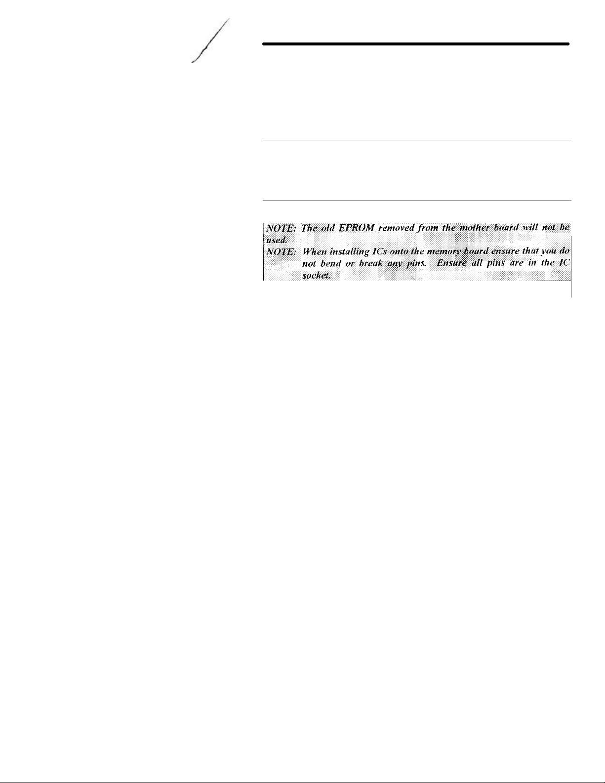
NOTE: When removing ICs from you
r TNC ensure
that you do not bend or break
any of the pins.
4. Using a small flat tip screwdriver remove the following ICs from your TNC.
Please take note as to the orientation of the ICs as you remove them.
U13--74HC4066 U25--NEC 43256-IOL or Equiv.
U22--ZO840004PSC Z80 CPU U23--SYSTEM EPROM
5. Install the ITs which were removed from your TNC in the above step.
Take note as to the orientation of the IC. Match up the NOTCH on the IC
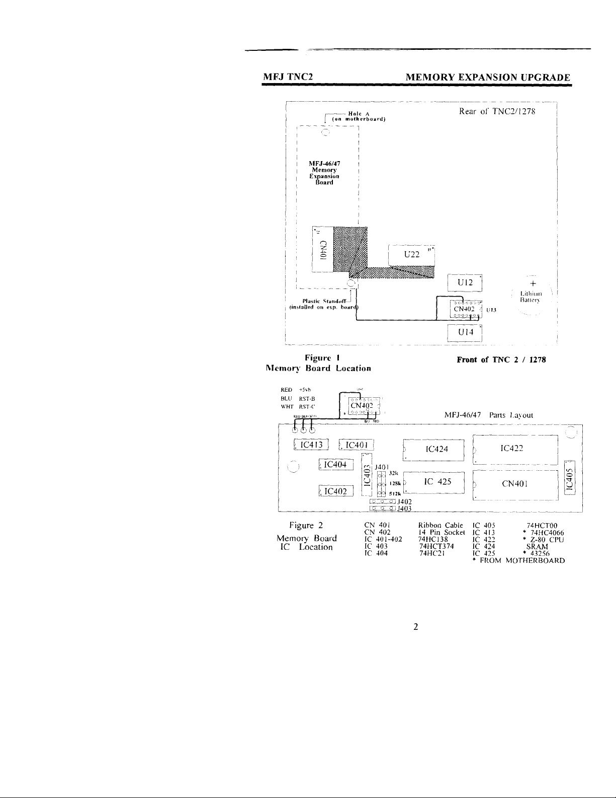
to the NOTCH on the IC socket on the expansion board. Refer to Figure 2
parts layout diagram for proper installation of the ICs.
18
Page 4
MFJ TNC2
Install the ITs removed from the mother board to the memory board as
follows:
74HC4066 (U13) in socket IC-413
43256 (U25) in socket IC-425
Z80 CPU (U22) in socket IC-422
A new EPROM with the new firmware is packaged with the memory kit. You
will install the new EPROM at U23 on the mother board. Be sure to orient the
new EPROM the same way in which you removed the old one. In order to do this
properly you must first position the TNC so the front panel is facing you. this is
very important. Then locate the NOTCH on the new EPROM. Now install the
new EPROM with the NOTCH pointing to your left.
7. Check and make sure that there no IC pins are bent under the IC itself. Check
and make sure that no IC pins are broken off. and that all IC pins are
inserted in the IC socket. Do this before proceeding beyond this point.
8. Set the memory board aside for now.
9. Please refer to Figure 1 when performing this step. Using a small
phillips screwdriver remove the PC hold-down screw in the left rear
corner of the TNC mother board, this is refered to as HOLE "A". Do
not let this screw out of your sight, you'll be using it here shortly.
10. Take the l/2" hex spacer supplied and install it in HOLE A, as noted
in Figure 1 in this instruction. This is the same place where you
removed the screw in Step #8, and tighten it down. This is an
aluminum spacer DO NOT OVER TIGHTEN it, you will STRIP the
THREADS.
MEMORY EXPANSION UPGRADE
18
Page 5

MFJ TNC2
11. Now with the memory board in one hand, plug the free end of the 40pin ribbon cable into the IC socket labeled U22 (please refer to Figure
l; this is the same one which you removed the Z80 CPU from earlier in
this procedure) on the mother board. Be sure to orient the blue
connector so that pin 20 and 21 on the blue connector are oriented
to the right side of the IC socket, (with the front panel of the TNC
facing toward you). You will need to twist the cable slightly. Ensure that
you leave the CN402 pigtail free and clear, do not let it become
pinched or caught up underneath anything.
NOTE: If you do not have an MFJ-2400 board installed in the TNC skip to
step 14.
12. If you have an MFJ -2400 modem installed position the 40-pin cable, so the
cable is not going to be pinched by the mounting stud for the MFJ-2400
modem.
13. Now you can re-install your MFJ-2400 modem. Be sure that you do not pinch
any of the wires of the 40-pin ribbon cable or the CN402 pigtail when you
tighten the MFJ -2400 down. This will cause problems with both the MFJ2400 and the memory board. So be sure and double check this.
14. Find the original hold-down screw which you removed from the TNC mother
board earlier. Secure the memory board to the l/2" spacer which you
installed earlier. Again this an aluminum spacer, DO NOT OVER-
TIGHTEN it! You will STRIP the THREADS.
15. Take note of the location of the NOTCH on CN402. Now plug CN402
into the IC socket labeled U13 (socket which the 74HC4066 ryas removed
earlier) on the TNC mother board. Please refer to either Figure l. Plug it
in so the NOTCH is pointing toward the lithium batten. Make sure it is
firmly in place!
MEMORY EXPANSION UPGRADE
18
Page 6

MFJ TNC2
16. Remove the paint (if any) from around the mounting holes on the
outside of the chassis and the inside of the cover. This can be done
with either light sandpaper or a knife blade. This will eliminate any
EMI from the TNC caused by the additional large ribbon cable.
This concludes the installation of the mailbox memory expansion board.
However. before you start putting things back to together double
check ever thing you have already done.
Final Inspection
Before closing up the TNC it would be best at this time to do a final
inspection of your installation. Please check all of the following:
I . Check all connections to ensure that they are all secure.
2. Make sure that there are no pins bent or broken on any of the IC's or
connectors installed in this procedure.
3. Make sure that there are no wires pinched or caught up under any of the
screws. circuit boards or connectors.
4. Last but not least give your TNC one last physical look over, for any debris or
foreign matter on the main PC.
If all of the above checks out then you can re-install the battery jumper
JMP5. Connect the computer cable to the TNC apply power and see if you
can obtain the TNC's sign-on messagc. If not, then go back and double
check the entire installation procedure. If the TNC signed on properly, install
the cover.
After properly installing the memory board. reconnect your TNC to your radio
and computer. If the TNC signed your installation is successfully. Follow the
instruction given by the upgrade documentation to operate your mail box.
MEMORY EXPANSION UPGRADE
18
Page 7

MFJ TNC2
47 Mailbox Memory Expansion
use
IC please
RAM IC on
by replacing IC424
ITEM No
RAM TYPE
J401 POSITION
TNC2.
upgrades will
The firmware
47 upgrades will also function in the MFJ
When upgrading the EPROM remember to
74
When upgrading the EPROM
47 installed remember to
RAM EXPANSION AND FIRMWARE EPROM UPGRADE
The RAM on each version of the MFJboard is upgradable. Either version of the MFJ-47 Expansion board can
either 32K, 128K. or 512K RAM IC. When interchanging the RAM
follow the MFJ -47 instruction manual for jumper positions. The
the MFJ -47 Mailbox Memory Expansion is changed simply
on the memory board and relocate the jumper at J401
header. Refer to Figure 2 and the following chart.
ordered from MFJ Enterprises, Inc.
MFJ-45A 432456LP-10 (32K) The (2) inside most pins
MFJ-45B 431000LP-10 (128K) The (2) middle pins
MFJ-45C 8512LP-10 (512K) The (2) outside most pins
There is only one version of the firmware EPROM upgrade for the MFJ
First of all the firmware version enclosed with the MFJ-47
function in MFJ-1270/1270B/1274 with the MFJ-47 installed.
version enclosed with the MFJ1270C and MFJ-1274C TNCs.
request the EPROM upgrade. MFJ-40CX.
Secondly. there is another firmware version for the MFJ1270/1270B/12
without the MFJ -47 installed. MFJ-40A. B, or C.
in an MFJ -1270/1270B/1274 TNC without the MFJ request the EPROM upgrade. MFJ40C.
MEMORY EXPANSION UPGRADE
RAM chips can be
18
Page 8

MFJ TNC2
RELEASE 1.1.4 NOTES:
FIXES
• Transmitted I-frames under Level 2 Version 2 did not have their P bits set
at the appropriate times. In fact. they never had their P bits set. This has
now been fixed. The last I-frame of a multiple I-frame transmission has its
P bit set.
• A mistake in the protocol state table was fixed.
• bbRAM scanning now checks all ten possible connection control structures
(instead of just the first one).
CHANGES
• AX25L2V2 defaults to the ON position.
• Major change made to AX25L2V2 handling. If retie limit is exceeded. or
the TNC receives a "disconnected" response to a poll. the connection is
ended
The old method (and the one proscribed) is fraught with problems for automated
stations that can not recover without an indication of loss of the connection.
The PERMCON control will replace the functionality of this aspect of
AX25L2V2 which was removed.
ENHANCEMENTS
MEMORY EXPANSION UPGRADE
• 32K of RAM is now expected. Virtually all of the new space is used to
enlarge existing queues within the TNC, yielding greater
performance especially at faster RF data rates. and making the onboard message buffer capability a bit more useful.
• The MCOM command decodes all control fields.
For I and S frames, sequence number information is also presented. Frames
compatible with the AX.25 Level 2.0 standard are also decoded as to the state
of the Command/Response (C/R) and Poll/Final (P/F) bits.
18
Page 9

breakdown of the
25 Level 2
MFJ TNC2 MEMORY EXPANSION UPGRADE
Ex: WA7GXD>KV7B <I C SO RO>: Hi
And so on. See Chapter 9 Table 9-1 in Four TNC 2 manual for a
control field codes. For complete information on the AX.
Version 2.0 Protocol, please refer to the ARRL AX.25 Protocol
Specification document. available from ARRL.
Dan,
WA7GXD>KV7B <I C P S I RO>:
have you been on EIES lately?
KV7B>WA7GXD <RR R F R2>
KV7B>WA7GXD <I C P SI R2>:
I was just thinking about that. I heard that @(username)
made some real
unbelievable comment on it!
WA7GXD>KV7B <RR R F R2>
WB2SPE>KV7B <C>
KV7B>WB2SPE <DM>
KV7B>WA7GXD <I C P S2 R2>:
Good conditions now
WA7GXD>KV7B <RR R F R3>
WA7GXD>KV7B <I C P S2 R3>:
Yes @(username) did. It was quite remarkable.
18
Page 10

MFJ TNC2 MEMORY EXPANSION UPGRADE
NEW COMMANDS FOR 1.1.4
CBELL ON:OFF Default: OFF
Parameters:
ON Connect bell enabled OFF
Connect bell disabled
This command is used to control whether an ASCII $07 (BELL) character
is sent as part of the connected message.
When set ON. the bell character immediately precedes the asterisk portion of
the connected message, e.g.:
<BELL>*** Connected to: <callsign>
CM5GDISC ON:OFF Default: OFF
Parameters:
ON Automatic disconnect enabled OFF
Automatic disconnect disabled
This command controls whether or not the 1F7 TNC will initiate a
disconnect sequence after it is connected to.
If CMSG is OFF, or CTEXT has no connected text, the TNC initiates a
disconnect immediately upon receiving information or acknowledgment frames
from the other station.
If CMSG is ON end CTEXT contains some text information, the TNC
initiates a disconnect after the packet containing connect text (CTEXT) is
acknowledged.
18
Page 11

MFJ TNC2 MEMORY EXPANSION UPGRADE
This command controls whether TNC 2 responds to ASCII Line Feed
Counts how many times frames were discarded because the
This command may be useful to bulletin board operators or others with a
need to send a short message. confirm its receipt. and disconnect.
LFIGNORE ON:OFF Default: OFF
Parameters:
ON TNC will ignore <LF> characters. OFF
TNC will respond to <LF> characters.
(<LF> $OA) characters or ignores them in command and converse modes.
When turned on_ line feeds are totally ignored except in transparent mode.
New HEALTH Counters
BBfailed n: Counts number of times bbRAM checksum was in error.
TXQovflwn:
outgoing frame queue was too small.
18
Page 12

MFJ TNC2 MEMORY EXPANSION UPGRADE
RELEASE 1.1.5 NOTES
FIXES
• Release l. l.4 suffered from a spurious condition where the HDLC
transmitter would time out. When this happened TXQOVFLW would
typically show a non-zero count. Release l.l.5 incorporates an HDLC
transmitter timeout feature to capture and recover from the timeout error.
• DWAIT operation has been fixed.
NEW COMMANDS FOR 1.1.5
BBSMSGS ON:OFF Default: OFF
This command controls how the TNC displays certain messages in command
and CONVERSE modes. The messages affected are described
below
MESSAGE EFFECT WHEN BBSMSGS ON
***CONNECTED to xxxx A newline is added just before"***"
***DISCONNECTED "
***retry limit exceeded "
***xxxx Busy "
***FRMR sent "
* * * FRMR rcvd " ***Connect request:xxxx- This message is
om itted.
The BBSMSGS command is primarily useful for host operation. Primarily with
WORLI and like bulletin board systems that require link status messages to
begin in the first output column.
The connect request message is omitted during BBSMSGS mode. This should
be most useful for preventing corruption of messages when forwarding with
small frames.
TXTMO: Counter Default: 0
TXTMO is a new addition to the TNC health-group. This register may
accumulate counts as the TNC successfully recovers from HDLC transmitter
timeouts. This is not a useful command for the majority of the users.
18
Page 13

MFJ TNC2 MEMORY EXPANSION UPGRADE
1270B/1274 to act as a modem for a host
to run
used the
Weather FAX reception is now possible for users who use IBM and
With
1287B
1284/1249
1282 for
the
instruction set,
the computer to
various
computers. The most
TCP/IP networking
RESTART
times when initially
subsequent power on/off
RELEASE 1.2.6 NOTES
ENHANCEMENTS
1. KISS enables the MFJ-
computer. Turning KISS on allows the MFJ-1270B and MFJ -1274
programs such as TCP/IP. MSYS and other programs which
Serial Link Interface Protocol (SLIP).
2.
compatibles. Macintosh or Commodore C64/128 computers.
these computer. to receive weather FAX you must use the MFJ starter pack for the Macintosh computer. the MFJstarter pack for the IBM and compatibles or the MFJcommodore C64/128.
3. The MNonax25 command is installed. When this command is turned ON.
the display of non-AX.25 packets is inhibited.
KISS COMMAND OPERATION
KISS ONOFF Default: OFF
Parameters:
ON Serial Line Interface protocol (SLIP) is used between the TNC and
attached computer. The TNC executes a very limited
arbitrating channel access only and depending on
handle all Level Two and higher protocol issues.
OFF The TNC operates using the commands and messages documented herein.
This is the normal mode of operation.
This command is used to enter the "KISS" mode for operation with
experimental protocols. KISS is used with intelligent host
popular use has been in conjunction with the KA9Q
software.
To operate KISS, enter the command KISS ON, then the command
(NOT RESET!). The CON and STA LEDs will flash three
activated. This command will then have effect for
cycles.
18
Page 14

MFJ TNC2 MEMORY EXPANSION UPGRADE
18
Page 15
MFJ TNC2 MEMORY EXPANSION UPGRADE
18
Page 16
MFJ TNC2 MEMORY EXPANSION UPGRADE
FAX pictures to screen
Note: The TNC will only return type 0 frames (received information).
Thus, the computer cannot interrogate the TNC to find the values of the
other command types.
WEATHER FAX OPERATION
To receive Weather FAX with the TNC 2 you will need to have software for your
computer to receive the picture and print it on the computer screen or to
save the pictures to disk. The MFJ-1284 or MFJ-1289 Starter Pack for the
IBM and compatibles computer. MFJ -1287 for the Macintosh or the MFJ-1282
for Commodore C64/128 allows you to print Weather
in near real time and to save Weather FAX pictures to disk. Weather FAX
pictures saved on disk can be sent to your printer, or recalled to screen at any
time. The TNC-2 FAX mode can receive FAX pictures transmitted in the 120
line per minute (2 linc/sec) format such as Weather FAX. Weather FAX are
received by the TNC 2 in the 2-level format. Multi-gray level FAX and other
FAX formats are not supported by the TNC-2,
FAX Frequencies
Most Weather Fax transmitting stations are usually found on the HF bands.
Weather FAX stations are generally upper sideband. Some of these stations
maintain a regular schedule. The frequencies of some Weather FAX stations
are:
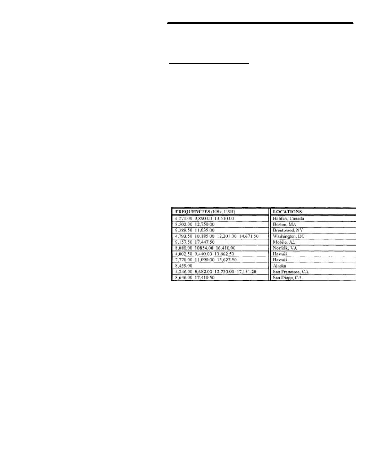
3,357.00 4,268.00 4,975.00 6,946.00 10,865.00 12,125.00 20,015 Other FAX
Frequencies and the station location are listed in the following chart. These
frequencies were obtained from Popular Communications Magazine:
18
Page 17

MFJ TNC2 MEMORY EXPANSION UPGRADE
Receiving Weather FAX
Connect an I -W Radio to the TNC 2 as described in the Radio
connection of the TNC 2 instruction manual. Set-up the TNC 2 for
VHF operation.
From the cmd: command mode, the TNC 2 can be set to Weather FAX
mode by typing:
FAX <CR>
At this point you will want to set your computer program to start printing the
Weather FAX picture on the screen. Do this according to the instruction
manual supplied with the software.
Once the program is properly set. set the audio output of your radio to normal
volume. Tune your radio to a desired frequency. If you are not familiar with
recognizing FAX signals. you may want to select one of the weather FAX
frequencies listed above. Weather FAX is usually transmitted at 1200 lines per
minute. This is a horizontal scanning rate of 2 lines per second. So by listening to
the scanning rate. you can determine if the TNC 2 is capable of receiving that
particular FAX signal.
After tuning in the desired FAX frequency. tune the radio so that the DCD LED
remains lit. Now observe the TUNING INDICATOR of the TNC2 while fine
tuning your radio (for TNC 2 with tuning indicator only). You will notice that
with each scan the tuning indicator will move toward the center. Tune the radio
so that the tuning indicator is centered at the end of each FAX scan. Once
you achieve this, the FAX signal is tuned in and the TNC 2 is ready to
decode the FAX signal.
Proper tuning of the FAX signal is very important for successful Weather FAX
receiving. Therefore, if your TNC 2 does not have a tuning indicator you
may find tuning difficult. An add-on tuning indicator. MFJ1273 is available
from MFJ Enterprises. Inc. for the TNC 2.
Once entering the Weather FAX mode, the TNC 2 is in standby-receive mode.
This means that the TNC2 is listening to the radio for the distinctive
"tic -tic" that indicates the synchronization period at the beginning of a
picture. If the TNC2 hears the "tic-tic" well enough. it will establish a lock to
the signal and start printing to the screen.
The TNC2's built-in LOCK detects the beginning of each picture before
starting to print. This insures each picture will be printed from top to
bottom. If you want the printer to start to print in the middle of the
18
Page 18

MFJ TNC2 MEMORY EXPANSION UPGRADE
picture. you may force a lock on the picture and the printer will begin to print
upon the "force lock". To force a lock. you simply type the letter "L"
while in the FAX standby -receive mode.
If the FAX picture appears to be printed shifted to the right. you can type the
"<" key to shift the picture to the left. Each repetition of the "<" key will shift
the picture 1/10" to the left. To shift the picture to the right. use the ">"
key. Each repetition of the ">" key will shift the picture to the right l/10". For
example, if you needed to shift the picture to the left I inch. you would press
the "<" key ten times. The picture can be shifted to the right or left at any time
during printing.
If the picture appears to be printing diagonally to the left or to the right, this
indicates that the master CPU clock on the TNC 2 may not be in frequency with
the transmitting signal. To correct this problem. you will need to remove the
cover of the TNC 2 and adjust the capacitor trimmer, C47. This adjustment
does not require am special equipment_ Simply adjust C47 about 1/8 of
a rotation at a time and let the primer print a few lines of the FAX picture.
If the picture seems to be getting worse. rotate the trimmer in the opposite
direction. Repeat this procedure until the picture is straight vertically.
Weather FAX pictures received can also be saved to the disk. This
operation is described in the software documentation of your computer
program.
Terminating FAX Printing
Printing of a FAX picture can be terminated at any time during the
printing. You must type a CTRL-C twice (CTRL-C. CTRL-C) in order to
terminate FAX printing. The TNC 2 will return to command mode, and printing
will stop.
NEW COMMANDS FOR 1.2.6
MNonax25 ON:OFF Default: OFF
MNonax25 is defaulted to OFF. When MNonx25 is OFF the display of nonAX.25 packets is inhibited. TNC 2 will display only AX.25 packets. Setting
MNonax25 ON will cause TNC 2 to also monitor non-AX.25 packets, for
example those associated with TCP/IP and NET/ROM or TheNet links.
Display of non-AX.25 packets may not be understandable to the user.
18
Page 19

MFJ TNC2 MEMORY EXPANSION UPGRADE
RELEASE 1.2.7 NOTES
In the TNC2 Firmware Release l.2.7 the new packet anti-collision features.
ACKNOWLEDGMENT PRIORITY and SLOTTING is installed.
These features minimizes packet collisions in a busy channel. Use of the
optional SLOTTING and ACKNOWLEDGMENT PRIORITY procedures
now in the MFJ TNC firmware significantly improve the reliability of
packet radio connections on shared channels. The greatest improvement is
yielded when all stations in a network are so equipped and configured with the
appropriate. matching parameters.
THE IDEA
The idea behind the prioritized acknowledgment (PriACK) protocol is quite
simple. Acknowledgments (ACKs) get priority access to the channel so that
time is not wasted retiring packets that have already been correctly copied by the
remote TNC. In normal AX-25 practice, for a variety of reasons. the ACK is often
not received within the time limit defined by the FRANK (TI) protocol timer.
In fact, because "channel access" methods are not clearly defined in the AX.25
Level Two Version 2.0 protocol document. the present protocol is more likely to
synchronize collisions with acknowledgment packets than with any other type
of packet!
THE PROBLEM
When a channel becomes clear, if your TNC has something to send, it will
immediately send it. Unfortunately. if anyone else's TNC has something to
send. it will also "jump on" the channel as soon as it becomes clear.
The result is collisions and retries. Only after a collision does the present
protocol suggest using random backoff. Thus, an acknowledgment to a justreceived packet is almost assured of a collisionand-retry sequence.. even though
the TNC correctly received the packet. This will usually cause the TNC which is
awaiting the ACK to time out and re-send the data.
To this collision synchronization mechanism. AX.25 Level Two Version 2.0
adds a propensity to cause even ACKs which are not from hidden
terminals, and thus less susceptible to collision, to be delayed beyond even
generous FRANK timer settings when the channel gets busy.
18
Page 20

MFJ TNC2 MEMORY EXPANSION UPGRADE
Once FRACK times out, even if the ACK finally makes it through before the
retry is sent. the original packet is retried an way. This wastes a lot of time
which could be better used clearing the channel of some of the legitimate
offered load. This feature of AX.25 Level Two protocol accounts for much
of the abysmal performance of the currently popular NETROM and TheNet
nodes when used with omnidirectional antennas systems.
HOW IT WORKS
PriACK protocol avoids the above problems by giving ACKs priority access to
the channel. It does this in such a way that even ACKs coming from hidden
terminals are usually protected from collision.
Standard AX.25 protocol gives a limited version of this priority access only
to digipeated frames through the DWAIT timer.
Ack prioritization works with slotted channel access in the following way:
1. Response frames (ACKs) are always sent immediately upon receipt of a valid
packet. Ultimately, not even DCD will be checked for sending an ACK.
However, in this release DCD will still hold an ACK off the channel.
2. Stations queued up to access the channel but waiting for a channel busy
condition (DCD true) to clear_ will start a slotted access procedure only
after enough time for a response frame to clear the channel has
transpired (ACKTIME). This is true even if the TNC waiting to use
the channe l cannot hear the ACK being sent.
3. Slot tinge windows (DEADTIME) are set large enough to ensure the
local TNC will be able to accurately determine if another detectable station
has started transmitting in any slot proceeding the slot selected by
the local TNC. This prevents two TNCs which have selected adjacent
slots from colliding.
As you can see. under this protocol there will never be a condition when
an ACK is delayed from being sent beyond the FRACK timer limitation.
However, the FRACK timer is still active,. and must be set to a value that
is long enough so as to allow enough time for the
(MAXFRAME*PACLEN)+ACKWAIT timer to expire before FRACK
does. This time will depend on the radio and radio channel data rate is
use. The TNC knows that if it doesn't see the ACK immediately when
expected. it is probably never going to see it. (See discussion of new
19
Page 21

MFJ TNC2 MEMORY EXPANSION UPGRADE
parameters below for definition of ACKWAIT.)
Forcing a channel access delay for all stations on the channel which are
waiting for a chance to transmit allow ACKs from hidden terminals to get
back to the expecting station. This clears that traffic from the offered channel
load. If the packet was indeed copied and ACKed. further retries of the same
information will not be necessary.
57
Page 22

See the
command description elsewhere in this document for their meanings and
This timer actually consists of the same of ACKTIME + DEADTIME. It
has
be sent on
One is
other
equire to
Most
using
its packet
being used for
This is because, in many TNCs. the
than at the end! Thus,
whatever data rate you are
ME 7 PACLEN 255
This way
PACLEN without having to worry about
MFJ TNC2
NEW PARAMETERS
There are several new parameters needed for PriACK operation.
settings.
L ACKPRIOR
2. DEADTIME
3. ACKTIME
4. SLOTS
5. ACKWAIT (not directly user settable)
represents the time the queued up TNC will wait before transmitting if it
selected the first slot. This allows time for a hidden station's ACK to
the channel.
It is split into two timers because it has two unrelated components.
related only to the data rate being used on the channel (ACKTIME). the
is related only to the absolute time the radios and TNC DCD circuits r
determine that a transmitter is active after PTT is asserted (DEADTIME).
OTHER RELATED PARAMETERS
Several of the "standard" TNC parameters will affect PriACK operation.
of theses are parameters in TNCs on the channel which are not
PriACK.
FRACK
FRACK must be set correctly in any TNC regardless of protocol.
FRACK should be set to a value which allows time for the TNC to send
and receive the ACK. This value will depend on the settings
PACLEN and the radio port data rate.
FRACK timer starts at the beginning of the packet rather
it is best to set FRACK to its worst case value for
using on the radio port and still allow for MAXFRA
packets to be sent and allow other nonPriACK stations to collide.
you can make adjustments to
interaction with the setting of FRACK.
MEMORY EXPANSION UPGRADE
57
Page 23

MFJ TNC2 MEMORY EXPANSION UPGRADE
FRACK should be set to 8 for 1200 baud work and 16 for 300 baud
operation.
RESPTIME
If you are running PriACK on a channel where some of the stations have
long RESPTIME delays. those stations will not be able to successfully
communicate with you after connecting. If you wish to communicate with these
stations ,you will have to set your FRACK timer to a number which is longer than
the other stations RESPTIME delay. RESPTIME should be set to 0 in your
TNC when running PriACK. With proper DCD operation. RESPTIME 0
will work in any event.
DWAIT
DWAIT is ignored when running PriACK. However, when PriATK is OFF. or
if you are using a TNC which does not yet have PriACK capability. DWAIT
should be set to DEADTIME. or 33 (330 inSec) for the default.
TXDELAY
TXDELAY should be set to allow for the slowest radio on the channel. It
should be the same as DEADTIME and DWAIT. The default of 33 (330
mSec) is adequate for most work.
INITIAL PARAMETER SETTING SUMMARY
The setting for use at 1200 baud on a VHF FM channel are:
ACKPRIOR ON
SLOT 3
DEADTIME 33
ACKTIME 14
RESPTIME 0 (if you require a non zero value for this parameter in order to
prevent ACKing individual packet in a MAXFRAME
greater than I blast, you DCD circuit is not working.
Please get it fixed)
DWAIT 33
MAXFRAME 1-7 depending on channel quality
FRACK 8
57
Page 24

MFJ TNC2 MEMORY EXPANSION UPGRADE
and
newer.
Therefore, for purposes of testing the effect of the new system on channel
throughput. if there are stations on channel which are NOT using the
le with
would
stations
these settings.
that
This will
capture the
been cleared.
some type of
slots and
The settings to use for 300 baud work on a linear mode HF channel are:
ACKPRIOR ON
SLOTS 3
DEADTIME 8
ACKTIME 52
ACKTIME 8
RESPTIME 0
MAXFRAME I
FRACK 16
PACLEN 32 to 128 depending on channel quality WHAT to
EXPECT
This modification to the protocol is compatible with stations using the current
protocol in the following respect. A station using the new protocol will not
degrade the channel for users of the current protocol_ So there is nothing
wrong with firing up the new stuff on a channel where the majority of the
users aren't vet using it. You will be able to communicate with users of the
other system without difficulties.
Howeyer. if the users of the old channel access procedures have DWait
RESPtime set to 0. they will tend to hog the channel from users of the
more polite access system.
new system, they should set their DWait value to one that is compatib
the new system users. A reasonable DWait setting for 1200 baud use
be 73. For 300 baud work. it would be 76.
While these settings seem extremely long, they will assure that the
NOT using the new protocol always get a shot at slot #l. With
the users of the NEW protocol will occasionally capture the channel.
Settings of 43 for 1200 baud and 64 for 300 baud could be used to assure
stations NOT using the new protocol alyays have a shot at slot #0.
result in users of the new protocol almost never being able to
channel unless all traffic from users of the old protocol has
This should NOT be done unless ALL stations are using
slotted channel access procedure with compatible numbers of
compatible slot times.
57
Page 25

MFJ TNC2 MEMORY EXPANSION UPGRADE
Remember that the objective of the new channel access procedures is to
increase aggregate throughput for the CHANNEL. not necessarily for an
individual user. It may seem to you at first when you get on a very busy channel
where you are the only station that is using the new system, that you aren't
getting to transmit very- frequently. This is because you aren't getting to transmit
very frequently. However. the OTHER users on the channel will see an
incremental increase in the overall amount of data that the channel can pass
per unit time because you are being such a nice guy. Remember that
transmitting isn't necessarily communicating.
There is ONE benefit that you should be able to see even under the above
circumstances. If you are communicating with another station who is also
running the news system, the channel should appear more reliable to you even if
quite slow. You should not be getting retried out waiting for his ACK to co me
back & have to keep reconnecting.
As a higher and higher percentage of the users on the channel begin
using, the new system. the performance of the channel should increase quite a
bit. However, we all must remember that if a channel is mathematically c apable of
transferring (for example) 1000 characters per unit time. the very best it can
possibly do (if CSMA is working right) is reliably pass about 620 characters per
unit time. If it is offered more than this to handle. performance falls off
sharply with increased offered load. Currently the typical AX.25 simplex
channels observed on the HAM bands tend to hover around 10 to as high as
18 percent throughput. This is far below the 62 percent that is possible when the
protocol is working right.
57
Page 26

MFJ TNC2 MEMORY EXPANSION UPGRADE
NEW COMMANDS FOR RELEASE 1.2.7
ACKPRIOR ON/OFF Default: ON
Parameters:
ON Enables Prioritized acknowledgments
OFF Acknowledgments have the same priority as any other frames on the
channel.
When ACKPRIOR is ON. acknowledgments have priority. This means that is
your TNC receives a frame that it must acknowledge (ACK). it will
immediately send the ACK if the channel is clear. If other stations are
pinning with ACKPRIOR ON. they will not access the channel until you have
had a chance to send the ACK. even if they cannot hear your transmissions.
When OFF. acknowledgments are queued up for transmission the same as any
other frame.
ACKTIME n Default: 14
Parameters:
n 0-250 in 10 mSec increments.
ACKTIME specifies the time required to send an RR or RNA response
frame (an acknowledgment) to an I frame at the radio port data rate. This
corresponds to about 510 mSec at 1200 bps with 8 digipeaters and about
1.10 mSec at 1200 bps with no digipeaters. The default of 140 mSec (ACK
14) allows for no digipeaters.
57
Page 27

MFJ TNC2 MEMORY EXPANSION UPGRADE
CHECKV1 O N/OFF Default: OFF
Parameters:
ON Enables CHECKtime (T3) when punning AX.25 Level 2 Version 1.0
protocol. This will result in an automatic disconnect when packets haven't
flowed between this TNC and the remote TNC for CHECKtime. See
CHECK command.
OFF Disables the CHECKtime tinier (T3) and requires the operator 1 initiate a
disconnect sequence. This is in accordance with AX.25 Level 2 Version l.0
procedures.
When ON. the CHECK (T3) timer is used to automatically disconnect an
AX.25 Level 2 Version 1.0 link when data hasn't flowed for CHECK time
Note that T 3 is not defined for Version 1.0 operation. See CHECK command.
When OFF. T 3 is ignored and normal Version 1.0 procedures apply.
Note: Many operators prefer suing Version 1.0 protocol. especially on marginal
or noisy links in order to eliminate some of the overhead of AX.25
Level 2 Version 2.0 protocol.
DEADTIME n Default: 33
Parameters:
n 0-250 in 10 mSec increments.
DEADTIME specifies the time it takes a station's receiver to detect the fact
that a remote transmitter has keyed up. It should be set to the time of the
slowest acceptable radio on the channel. It must also allow for any squelch
delays and DCD lock time. DWAIT and TXDELAY should also be set to this
same value for everyone in the LAN.
A fairly fast VHF FM radio-plus-TNC might take 210 mSec (DEA 21), while
an HF radio-plus-TNC will usually respond in 80 mSec (DEA 8). Some
multi-mode radio-plus-TNCs operating at 1200 bps may respond in only 40
mSec (DEA 4). The default value (DEA 33) will safely cover the majority of
FM radios in common packet use.
57
Page 28

MFJ TNC2 MEMORY EXPANSION UPGRADE
RNA is sent. When the
sent. When the
2 receives an RNR, it will not poll the sending TNC until {TO*
10 seconds". TO = CHECKtime*8 unless CHECKtime*8 is <30 or >253
will resend the data every
Level 2
g data receives an
sending TNC
(FRANK) time until
accepted the data. This often
2 will stop sending data upon
(see
active. If
2 sent the RNR, then it will send an R when its buffers have
2.
Setting FIRMRNR ON improves channel efficiency, but is
2 releases. The incompatibility is a
should be alyays be set
conversing with network nodes, for example. NET/ROM. In
eft OFF unless you can
FIRMRNR ON/OFF
Default: OFF
Parameters:
ON When the MFJ TNC-2's buffer is fill. an
buffers are no longer full, an RR command frame is
MFJ TNC-
in which case TO = 12.
OFF When the MFJ TNC-2's buffers fill. an RNR is sent as a response to an I
frame.
When the MFJ TNC-2 receives an RNA. it
FRACKtime (TI) until an RR is received. When OFF. standard AX.25
Version 2.0 protocol procedures are used. If a TNT sendin
RNA. meaning the remote TNC cannot accept more data. The
(MFJ TNC-2) will continuously re-send the data even TI
an RR is received. meaning the remote TNC
results in a lot of unnecessary channel congestion.
When FIRMRNR is ON, the MFJ TNCreceipt of an RNR. If the remote TNC does not send an RR before ]TO]
above). the MFJ TNC-2 will poll the remote TNC to be sure it is still
the MFJ TNCcleared to allow more data to be received.
FIRMRNR controls the handling of busy states by the MFJ TNC-
incompatible with earlier TNC-
result of vague protocol specifications. FIRMRNR
ON when
other cases. it is recommended that FIRMRNR be l
be assured the other TNC you are connected to supports FIRMRNR.
57
Page 29

MFJ TNC2 MEMORY EXPANSION UPGRADE
SLOTS n Default: 3
Parameter:
n 0-127
SLOTS specifies the number of "slots" from which to choose when
deciding to access the channel. For example, SLOTS 3 means there are three
slots, each having a probability of l/3 to be selected. Each slot is DEADTIME long.
If SLOTS 0 is chosen, the TNC will act as if SLOTS I had been selected.
Other implementations of this idea of channel access use "PERSISTENCE" to
decide the probability of channel access when the channel is clear and
"PPERSISTENCE" to enable or disable this feature.
A low value means a greater chance of attempting to send data when the channel is
clear, and a higher value means less chance. Normal AX.25 practice is to have every
station jump on the channel when it goes clear. virtually assuring collisions and
retries.
SLOTS and its relation to the more common "PPERSISTENCE" and
"PERSISTENCE" commands are given below:
PERSISTENCE PROBABILIT Y TO
` SLOTS
PPERSISTENCE
XMIT
I OFF 255 Jump on = 100%
2 ON 127 Jump on = 50%
3 ON 85 Jump on = 33%
4 ON
3,
6
Jump on = 25%
5 ON 51 Jump on = 20%
and so forth.
A typical value would be 2 or 3 for a channel with a few other users and 5 to 7
for a fairly busy channel. Higher values than about 10 imply the channel is
too busy and other frequencies should be used if available.
Note: SLOTS is independent of ACKPRIOR.
57
Page 30

MFJ TNC2 MEMORY EXPANSION UPGRADE
57
Page 31

MFJ TNC2 MEMORY EXPANSION UPGRADE
57
Page 32

MFJ TNC2 MEMORY EXPANSION UPGRADE
TXDIDDLE ONIOFF Default: ON
TXDIDDLE determines whether or not the MFJ TNC uses a highly
efficient square wave signal in place of flags during the transmitter delay
(TXDELAY) period. When TXDIDDLE is ON, you may select even
smaller TXDELAY intervals because the square wave presents four times as
many transitions as TXDIDDLE OFF does for your connectees' receive
synchronization.
TXDIDDLE is defaulted to the ON setting to reflect the increased
efficiency. However there are a number of TNCs on the market which
purport to be AX.25 compatible but do not recognize valid AX.25 packets
preceded by the TXDIDDLE keyup technique. You may recognize the need to
set TXDIDDLE OFF if it appears that the station you're working is unable to
successfully receive your packets despite your adequate signal.
This failure of some TNCs to receive TXDIDDLEd packets may be a
result of some software carrier-detect schemes. All TAPR and derivative TNCs
utilizing hardware-generated carrier-detect receive both TXDIDDLEd and
non-TXDIDDLEd packets with equal efficiency.
Note that when TXDIDDLE is OFF. TXDELAYC is irrelevant! Therefore,
the actual TXDELAY yielded when TXDIDDLE is OFF is equal to
TXDELAY* 100ms plus an AXDELAY time.
57
Page 33

will "flush its buffers" to the radio port upon loss of
and ID frames as unconnected
(U1) frames. It will discard information in its buffers upon loss of
TNC
unconnected
useful
unacknowledged data in the
nection is lost. The normal behavior of a TNC
frames, adding to channel congestion. The
serves to reduce channel congestion because the
MFJ TNC2 MEMORY EXPANSION UPGRADE
TXUIFRAM ON OFF
Parameters:
Default: OFF
ON The TNC
connection.
OFF The TNC will only send BEACON
connection. connection. This command determines whether the
will transmit most unconnected information packets.
Setting TXUIFRAM OFF will prevent all but BEACON and ID
("UI") frames from being originated and transmitted. This is most
BBS and other stations which lend to leave
TNC transmit buffer when a con
would send the buffered data as "UI"
behavior with TXUlfrme OFF
non-useless data is never sent.
57
Page 34

57
Page 35

MFJ TNC2
MEMORY EXPANSION
RELEASE 1.2.8 NOTES
In firmware Release l.2.8 the Host Mode feature and the QRA ("Who are
you") command are installed.
Host Mode requires a special terminal program to operate. Documentation for
Host Mode is available on disk from MFJ upon request.
QRA ("Who are you") pinging is supported in release l.2.8. A QRA ping polls
all of the TNCs within range. A random number of seconds later. each TNC
that heard the QRA ping will transmit its identification packet. The purpose of
this feature is to reveal to the packeteer, particularly the transient one. the
names of all reachable TNCs and digipeaters.
Sending a QRA ping:
1) Set the unprotocol callsign to QRA
cmd: UNPROTO QRA <ENTER>
2) Manually send an unconnected packet
cmd: CONVERSE<ENTER>
<ENTER>
AC
cmd:
NEW COMMANDS FOR 1.2.8
ANSWRQRA ON OFF Default: ON
Parameters:
ON MFJ TNC responds to non-digipeated Ul frames addressed to QRA, within I
to 16 seconds, with an empty ID packet.
OFF Disables MFJ TNC's ping-response function.
QRA ("Who are you") pinging is supported in firmware release 1.2.9 of
your MFJ TNC. A QRA ping polls all of the TNCs within range. A random
number of seconds later, each TNC that heard the QRA ping will transmit its
identification packet. The purpose of this feature is to reveal to the
packeteer, particularly the transient one, the names of all reachable TNCs
and digipeaters.
57
Page 36

MFJ TNC2
MEMORY EXPANSION
Sending a QRA ping:
have
The MFJ
monitored
other than ASCII
monitored or simply
all information packets
etc). When MNONPRIN is
printable characters are
command helpful when there are binary transfers
you'd rather not monitor. MNONPRIN has no effect on any
4
l) Set the unprotocol callsign to QRA
cmd: UNPROTO QRA<ENTER>
2) Manually send an unconnected packet
cmd: CONVERSE<ENTER>
<ENTER>
AC
cmd:
This sequence will send an unconnected packet. Once the local TNCs
responded with ID packets. then the user can press a "CRTL-C".
TNC will respond with the cmd: prompt.
MNONPrin ONIOFF Default: ON
Parameters:
ON Enables printing Non-Printable Characters
OFF Discards all Packets containing Non-Printable Characters
The setting of the MNONPRINT parameter determines whether
packets containing non-printable characters (i.e., characters
CR, LF, BEL, and not between $20 and $7e) are
discarded. The default setting permits monitoring
(subject to LCALLS, MONITOR, MNONAX25,
OFF, information packets containing one or more nondiscarded. You may find this
on the channel that
of the data received during connections.
57
Page 37

MFJ TNC2 MEMORY EXPANSION UPGRADE
RELEASE 1.2.9 NOTES
In firmware Release l.2.9 major improvements have been made in the Easymail mailbox. The improved mailbox features can be used in the MFJ TNC2
with or without the mailbox memory expansion. However, in order for you to
fully benefit from this mailbox, we recommend that you install the memory
expansion board. The on-board MFJ TNC mailbox memory is approximately
8K. The user can increase the Mailbox Memory in the MFJ TNC to 32K.
128K or even 512K!! Memory in this additional RAM is backed up by the
lithium battery on the TNC motherboard. The memory expansion board can be
purchased separately and is easily installed by the user inside the MFJ TNC2. The
memory expansion board comes with different firmware. release 2.l and must be
used in place of the l.29 release firmware. When the expansion board is
installed, you must remember to request the release 2.1 firmware . when
ordering firmware upgrades in the future. The different versions of the
mailbox memory boards are listed below:
Above mailbox memory expansion boards are available from MFJ dealers or
from MFJ Enterprises. Inc.
EASY-MAIL MAILBOX
Now that you have upgraded your TNC with the MFJ-47 Memory
Expansion board, you have also expanded your Mailbox. The new EasyMail
mailbox is only valid for the HF and VHF packet modes. The operation
of the Easy-Mail mailbox is really quite simple. There is a command in
the MFJ TNC called MAILBOX. The new MAILBOX command is defaulted
ON, which makes your new Easy-Mail mailbox ready to use, as soon as the MFJ
TNC is powered ON. Anyone who operates AX.25 packet can access your
mailbox by establishing a connection to your station. A connection to your
station is done by suing the standard packet CONNECT command. However,
once connected the remote user can send messages or obtain a list of messages
in the mailbox. The remote user can also kill or read any messages that are
addressed to him.
57
Page 38

ry
can
512K
additional
motherboard.
Enterprises, Inc. and are
45B for 128K
ated independently from the standard packet
operation. There are certain commands which need to be set. These will be
3. If you want your messages time and date stamped. then set DAYTIME with
TNC main manual, as
MFJ TNC2 MEMORY EXPANSION UPGRADE
The Easy-Mail mailbox in the MFJ TNC with the MFJ -47A Memo
Expansion installed, provides 32K message storage space. However. you
increase the mailbox memory in your MFJ TNC to 128K or even
by simply replacing the mailbox RAM chip on the MFJ-47. This
memory is also backed up by the lithium battery on the TNC
Additional RAM chip are available from MFJ
easily installed by the user. Order the MFJ -45A for 32K. MFJor MFJ -45C for 512K.
Setting Up your Ease-Mail Mailbox
The Mailbox can nosy be oper
explained later in this instruction.
NOTE: Whenever <ENTER> is found in this instruction this means to press
the RETURN key. not to type <ENTER>.
I. Under the cmd: prompt. type::
MYMCALL n <ENTER>: where n is the callsign you wish to for
your mailbox.
2. From the cmd: prompt type:
USERS 1 <ENTER>
the current information. Please refer to your MFJ
to how to set the DAYTIME parameter.
4. From the cmd: prompt type:
MAILBOX ON <ENTER>
57
Page 39

MFJ TNC2 MEMORY EXPANSION UPGRADE
Now your MFJ TNC is ready for simultaneous Mailbox/Packet operations.
You as the SYSOP can access your Mailbox by typing from the cmd: prompt:
SYSOP <ENTER> Your
MFJ TNC will respond with:
[K]MFJ -2.la-IHS]
Mailbox ready
n free Mailbox (B, E, H(elp), J, K, L, M, R, S, T) >
First of all lets find out what the n free is for. The n free is a "Bytes Free"
indicator. This applies only to the Mailbox. This is a great feature. because all
users will always know how much space is left in your Mailbox. The Mailbox
will update the "Bytes Free" whenever messages are forwarded. added or
deleted.
NOTE: The M command will not be in Release 1.2.9. This is due to the fact that
there is no Mailbox expansion in the Release 1.2.9.
Nov you are ready to operate your mailbox. However. lets take first things first.
You very well cannot operate the Mailbox without knowing the functions of the
commands. So. lets take a look at the functions of the Mailbox commands. The
functions are as follows:
B Logout: This initiates a disconnect sequence from the Mailbox.
E Edit Message Header: This allows editing of the message header. This is
necessary for the Forward and Reverse Forward functions of
the Mailbox. The current is first displayed, then the Mailbox
gets the new values. according to what is entered at the prompts it
gives the user. The local and remote SYSOPs may edit any
messages in the Mailbox. Remote users may only messages TO and
FROM himself and any message of 'T'raffic. Below are the edit
prompts and an explanation as to what their functions are:
To: The callsign of the person the message is going to goes here. It must be
different than MYcall or MYMcall.
@: The callsign of the BBS you wish to Forward the message to is placed here.
This BBS should be the one where the person whom you are sending the
message to gets his mail.
57
Page 40

MFJ TNC2 MEMORY EXPANSION UPGRADE
turn
here are a
are NTS (National Traffic System) type
hese
messages must be formatted in a certain way. Please refer to the
for more detailed view and information on this
via
N or a
in the
all other
messages
From: The callsign of the person who originated the message is placed here.
Type: The Type of message you are sending is placed here. This will
on a flag in the first flag box. There are a few message types. and
couple listed below:
1. "T" message--These
messages. This message system was developed by the ARRL. T
ARRL Nct Directory
message system.
2. "P" messages --These types of messages are still private to the
sender. recipient, and the SYSOP.
There are other types of messages supported by the Mailbox but without special
features.
Flag: The message Flag is now very important. All of flags can be set
the S (send) or E (edit) commands. This flag will either be an
Y. This will appear in the flag block closest to To: block
message header. There are different types of flags are as follows:
N Messages with this flag set are all able to forwarded, providing
criteria is met for a message to be forwardable). Only
with the N flag set. trigger the "You have new mail!" message.
T The T flag indicates that the message is an NTS message.
Y Messages with the Y flag set are eligible to be killed by the "K" global
kill command.
F This flag is set when a message is forwarded. Messages which are
eligible to foryarded are:
1. Messages where the N flag is set.
2. Messages that have no lei? addresses that are different from
MYMcall.
57
Page 41

MFJ TNC2 MEMORY EXPANSION UPGRADE
P Messages with this flag set are private to the sender, recipient, and the
SYSOP. Only the per son to which the message is addressed to
can read or kill it. The local or remote SYSOP can read or kill any
message in the system.
Here is an example of a Mailbox message with a Type flag and a message flag
inserted:
Slot:1 PN To:KB5JNZ From:KF5C BBS Bu lletin
The P is in the Type flag block. which indicates that the message is a Private
message. The N is in the Message flag block. which tells you that the message has
not been read by the callsign KB5JNZ. When KB5JNZ reads the message the N
flag will become a Y flag.
H(elp) This command displays the Mailbox command list. A brief description of
the commands available to user is given.
J This command replies with the TNC's MHeard list. The eleven most recently
heard callsigns will be displayed. The "J" command only applies to
remote users.
K Allows you to kill messages which are addressed to you. This works in
conjunction with the Y flag. In order to perform a Global Kill,
first of all of the messages to be killed during this must have the Y flag
set in the header. Secondly. all messages to be killed must have the
same callsign as MYMcall.
K## Allows you kill the message in slot nn, where nn is a particular slot number.
Remote users may only kill messages which are addressed only to
them or originated by them. The local and remote SYSOP can kill
any messages, depending on the setting of the new command
REMsysop. Please refer to the REMsysop for more detailed
information.
L This command allows the remote user. local or remote SYSOP to list all
messages in the mailbox. All of slots which are currently in use will
be listed. They all will have the slot number, flag field, the
destination callsign, originator callsign, subject field. Also the
Mailbox command line will be on the next line.
57
Page 42

MFJ TNC2 MEMORY EXPANSION UPGRADE
memory
indicated on the
which
is an example of a
The bank number will vary from 0 to 7
in
xample let's say that you are running a 128K mailbox. and a remote user
must be
applies only to an MFJ TNC which have the
MFJ-
47A, B, or C expansion board installed on Release 1.2.9x
9x
M This allows the remote user. local or remote SYSOP to change
banks in the mailbox ram. The current memory bank is
mailbox command line. The bank will be inside a pair of{ },
will be after the "bytes free" indicator. Below
typical command line from the mailbox:
nn free {n} Mailbox (B,E,H(elp),J,K,L,M,R,S,T) >
Where {n} is the bank number.
depending on the size of the expanded memory ram. The bank numbers
relation to the RAM size are as follows:
NOTE: There will be only one (1) number in the ; at anytime.
For e
wants to access memory bank # l. First a connection to your mailbox
made. Once the Mailbox command line is obtained the user will type:
M 0 <ENTER>
This will be received by your Mailbox and then your Mailbox will send back a
new Mailbox command line:
nn free {0} Mailbox (B,E,H(elp),J,K,L,M,R,S,T) >
Thus the {0} indicates the memory bank has been switched to bank #l.
NOTE: The "M" function
is used. installed and Release 1>L is used.
57
Page 43

MFJ TNC2 MEMORY EXPANSION UPGRADE
R This command lets you read messages addressed to you. When you list the
messages in the mailbox you notice an N flag next to the messages
which you have not read. Once you read those messages the N flag
will change to a Y flag. This is an indicator to both you and the
SYSOP that the messages have been read. From there you can
perform a global kill on all of your messages or the SYSOP can kill
them individually.
Allows you to read the message in slot nn. Where nn is a particular slot
number. This command works the same as the R command. except its for
reading the individual slots.
S call This allows the remote user_ local or remote SYSOP to send a
message to the designated callsign. "CALL" must be a callsign valid
under the same format as the MYCALL. CONNECT or other callsign
commands. You can also send messages in NTS (National Traffic
System) format. You will need to refer to the ARRL NET
DIRECTORY for more detailed information on the NTS system.
SP call This allows the remote user, local or remote SYSOP to send a
personal message to the designated cal lsign. This is a private
message and only the person to whom the message is addressed
can read or kill it. The SYSOP can also read the private
messages. When a private message is listed a P flag is shown in the
"Message Type" flag block. The P flag can also be inserted by the
originator or the SYSOP through the Edit command.
T This command allows the remote user to page the SYSOP. When the T
command is invoked from the remote user the following message
appears on the SYSOP's computer screen and it also is sent back to
the remote user's screen:
Paging SYSOP; any key aborts...
57
Page 44

t
MFJ TNC2 MEMORY EXPANSION UPGRADE
The Mailbox will page the SYSOP by ringing the SYSOP's terminal bell 30
times. If the SYSOP is at his or her terminal. the asterisk character will
appear on the screen even' time the terminal bell (CTRL-G) rings. If the
SYSOP does not answer the Mailbox will send the message back to the user
saving no answer. Below is an example of a typical screen:
Paging SYSOP; any key aborts...
*****************************No answer
The remote user may abort the SYSOP page by sending packet to the
Mailbox. If the SYSOP does answer the page then the SYSOP can enter CHAT
command. then converse one -on-one with the remote user.
This concludes the explanation of the commands which are on the Mailbox
command line. Now lets get into a little of the Mailbox operation. If you have any
questions about the Mailbox commands. we believe they will be answered in
this section.
57
Page 45

MFJ TNC2 MEMORY EXPANSION UPGRADE
Mailbox Operation
l. First establish a connection to the Mailbox station.
2. If the Mailbox of the station to which you are trying to connect with is
ON. then it will answer back with the Mailbox prompt:
[MFJ- 2.1a-IHS]
Mailbox Reads'
nn free {n; Mailbox (B,E,H(elp),J,K,L,M,R,S,T) >
The nn indicates the amount of RAM space available for
messages in the Mailbox to which you are connected to. The nn will be no higher than 65k, if a 512k or 128k Mailbox
is in operation. If the Mailbox is 32k then nn will be 32k. then nn
)sill he 32K.
Also: The {n} indicates the memory bank being used for the Mailbox. Please
refer to the explanation of the M command for the Mailbox in this section.
Now at this point all of the Mailbox arc available to you. You may then type M to
switch the memory bank of the Mailbox. K to kill a message, L to list all
messages, R to read the messages, S to send a message. B to logout and
disconnect from the Mailbox or H for the HELP menu.
To send a message the S or the SP commands must be used. It must be
used in conjunction with a callsign as in the examples below:
S KB5JNZ <ENTER>. this will send an ordinary message to the
callsign KB5JNZ.
or
SP KB5JNZ <ENTER>. this will send a private message to the
callsign KB5JNZ.
a. The Mailbox will respond with:
Title:
b. The user will enter the message subject (title) at cursor prompt, then
press the "RETURN" key.
57
Page 46

MFJ TNC2 MEMORY EXPANSION
UPGRADE
c. The Mailbox will respond with: Send msg; Control-Z or
/EX to end:
d. The user will then enter the message at the cursor prompt. If you
are using a 512K or 128K Mailbox then you can actually upload
disk files into the Mailbox. The 32K version has the same capability but
with 32K RAM capacity. At the end of the message press a Control-Z and
the RETURN key. The message will be sent.
c. Your message will be seen on the mailbox station's screen. then the
mailbox will respond with the mailbox command prompt:
nn flee {n) Mailbox (B,E,H(elp),J,K,L,M,R,S,T) >
Where nn is the "bytes free" indicator. This tells the user how much ram
space is available in your Mailbox. Also { n; is the indicator of the
current memory hank in use by the Mailbox.
There are two (2) different ways to kill messages. The first is give in the
example below:
A. To kill a message in a particular slot type:
K## <CR>
Where the ## is the message number you want to kill.
The Mailbox will respond with:
Message ## deleted;
nn free {n; Mailbox (B,E,H(elp),J,K,L,M,R,S,T) >
This is whether or not the message flag is set to an N or a Y. Note
that the remote users may only kill messages which are addressed
them. The originator can also kill the message. The local SYSOP can
kill any or all messages in the Mailbox.
57
Page 47

MFJ TNC2 MEMORY EXPANSION UPGRADE
B. You can perform a Global Kill on a group of messages which are
under the same callsign. To perform this two (2) conditions must
be met:
i. All messages must have been read and the message flag must be a Y.
ii. The callsign contained in the MYMcall must be the same as the
callsign in the MYcall command.
If the above conditions are met then all the user must type: K
<CR>
This w ill go out to Mailbox. then the messages with the message flags set to Y
and all of the proper callsigns will be killed. The Mailbox will respond back to
the remote user with all message numbers killed during the Global Kill process.
Also the Mailbox prompt gill be given again. The "bytes free" indicator will
be updated also. The SYSOP either remote or local can do a Global Kill.
The SYSOP must individually kill any messages.
5. The remote user or local SYSOP can List messages from the Mailbox.
In order to do this first the Mailbox pro mpt must be obtained by
either a connection to the Mailbox or through the local SYSOP command.
Then to List messages from the Mailbox type the following from the
cmd: prompt:
L <CR>
The Mailbox will respond with a list of currently used slots in the following
format:
Slot:## t m To: From: Subject:
Where Slot## column is the number of the slot that the messages are in.
The lower case t is the Type Flag block. The lower case m is the
Message Flag block. The To: column will contain the callsign of the
person who the message is addressed to. The From: column will contain
the callsign of the person who left the message. The Subject: column
will contain a brief message title.
57
Page 48

MFJ TNC2 MEMORY EXPANSION UPGRADE
Note that the number of slots for an MFJ TNC without memory
expansion
addressed
such as bulletins
two (2) different
SYSOP to read a
group of messages with the
conditions of the Type or message
read process. They can be set to an N. Y
The Mailbox will display all messages that are addressed to the same
If no messages exist for MYCALL, then the
by the slot number.
This is good for reading other messages like bulletins or
messages addressed to ALL. In order do an individual read
expansion board is 30. For an MFJ TNC with the memory
installed the maximum slots per memory bank is 99.
After the Mailbox lists all messages it will issue the Mailbox
prompt:
nn free (n; Mailbox (B,E,H(elp),J,K,L,M,R,S,T) >
6. Anyone who accesses the Mailbox can read messages or which are
to him/her. Also a message which is a addressed to ALL,
can be read by anyone. Messages can be read by
methods. Below are the two methods:
A. This method will allow the remote user. local or remote
group of messages. This is only good for a
same callsign as MY,-all. The set
flags have an effect on a
or an F. In order to perform this type of read operation:
R <CR>
callsign as MYCALL.
Mailbox will respond with: Not Found.
B. Messages can also be read individually
type the following from the cmd: prompt:
R## <CR>
Where ## is the slot number of the message that you wish to read. The
Mailbox will respond with the message from the slot specified. All
messages read will be in the following format:
Slot## To: From: Subject:
This is an example of a message from the Mailbox
57
Page 49

MFJ TNC2 MEMORY EXPANSION UPGRADE
Where Slot## column is the number of the slot which the messages are in.
The lower case t is the Type Flag block. The lower case m is the
Message Flag block. The To: column will contain the callsign of the
person who the message is addressed to. The From: column will
contain the callsign of the person who left the message. The Subject:
column will contain a brief message title.
Then at the end of the message the Mailbox prompt will be issued.
7. The remote user can also disconnect from the Mailbox without having to issue
a CTRL-C. D and a RETURN. All that needs to be done is to type B to
logout of the Mailbox and disconnect from the it. If you access your Mailbox
via the SYsop command. then you must issue a CTRL-C to exit the
Mailbox and return to command mode. The command prompt will indicate
the stream you are on. The command prompt may look like this:
[Acmd: where [A indicatcs that you are on packet stream A.
This is the only way the remote users can access your Mailbox. If you stay
in the SYSop mode then when a user tries to connect to your Mailbox he will
receive a message like this:
***CALLSIGN Busy
Disconncctcd
The SYSOP will receive a message like the example below when he is in the
SYSOP mode and someone tries a connect:
***connect request: CALLSIGN
57
Page 50

MFJ TNC2 MEMORY EXPANSION UPGRADE
Additional Mailbox Features
Other MFJ TNC mailbox features are as follows:
Forwarding:
The MFJ TNC Mailbox now has the ability to Forward mail to most
full service and personal mailboxes. This feature allows you to
compose your mail on your TNC, at your leisure, and then Forward the
resulting messages for eventual delivery.
Messages may be forwarded any one of three ways either manually. by
command, or by automatic forward. You can either forward messages
hourly, or by your local full-service mailbox's reverse forward request.
Manual and hourly forwards may proceed through up to eight (8)
digipeaters, allowing the messages to be forwarded through ROSE
switches. Also NODE forwarding is can be done too, thus allowing you to
forward mail through NETROM. THENET. and KA-NODE switches.
Please refer to the NODeforw command in this manual.
In order to conserve RAM, space the SYSOP may specify that
forwarded messages be killed upon successful forwarding. However, if
conserving RAM is not a concern, then forwarded messages will be
flagged "F". This flag will appear in the message flag block.
Messages with F flags will be saved in the mailbox for the SYSOP's
disposition.
All forwarding events are monitored on the screen, in order to inform
the SYSOP of the forwarding progress.
In order for a message to be eligible for the forwarding process two
(2) conditions must be met:
A. Messages must have N flags in the message flag block.
B. All messages must have an @ callsign in the message header.
57
Page 51

MFJ TNC2 MEMORY EXPANSION UPGRADE
The command used to forward a message is FO. All forwards must be
done in the stream cmd:mode. This command is by pressing a CTRLC while in the SYSOP mode. Below is a typical example as to how to use
the FO command:
FO CALLSIGN <CR>
Where CALLSIGN is the callsign of the destination mailbox. This
callsign must also reside in header of the message to be forwarded. The
message header can be altered through the Mailbox Edit command.
Please refer to the EDIT command in this manual. When the FO
CALLSIGN is issued the MFJ TNC will initiate a connect request to the
destination BBS. If the connection is successful the your mailbox will
proceed to send the message to the destination BBS.
Eliciting Reverse Forwards
This yen- unique feature. when combined with the hourly automatic
forward. enables the MFJ mailbox to query another BBS. regularly and
automatically. for the purpose of polling the other BBS for the TNC user's
mail. Thus. even if your local full-service BBS operator is unyilling to
forward to you. you can still have most of the benefits of autoforwarding, because your own TNC will elicit your mail for you on an
hourly basis.
Reverse forwards may be restricted to a particular callsign. This
prevents others users from "stripping" messages off of the mailbox
prior to their being forwarded to the legitimate destination.
When all messages are forwarded.. if the destination mailbox
supports reverse forwarding (as determined by $ in it's SID) then the
MFJ TNC will attempt to elicit a reverse forward.
Remote Heard Log:
This handy feature allows the remote user to query the TNC heard log
at any time. From this log the remote can determine band
conditions, or just see who has been around. The log holds eleven (11)
of the most recently stations.
57
Page 52

MFJ TNC2 MEMORY EXPANSION UPGRADE
standard
a mailbox
like a regular
maybe with the
terminates any user or
mailbox will stay in Chat
SYSOP's
will poll the terminal's
receive
can go
For more detailed
this feature please refer to the section on Mailbox Set Up in
an
useful in
allow him to
duties, such as
for forwarding
This is a message dedicated to the Mailbox, but is used when a
characters
Chat Mode:
The Chat mode feature in the MFJ TNC Mailbox is s imilar to the
TNC "converse mode". It enables the SYSOP to break onto
link, and get one-on-one with mailbox user. This is just
"Packet QSO". This is good for discussing problems
link or with the mailbox in g eneral. Chat mode
forwarding operation in progress. The
mode until the SYSOP returns to command mode.
Page SYSOP:
This allows the remote user to "Page" the SYSOP by ringing the
terminal bell. This is done by the SYSOP's mailbox sending a CTRLG to the SYSOP's terminal. The SYSOP's mailbox
bell 30 times. If the SYSOP does not answer the remote user will
a message back saying No Answer. If the SYSOP does ansyer then lie
into the Chat mode. and converse with the remote user.
information on
this manual.
Remote SYSOP:
The Mailbox has the capability to be remotely controlled. A callsign c
be specified by the SYSOP for this purpose. This would be
the case where the SYSOP is out in the field. It would
control the mailbox. and do most of the local SYSOP's
killing messages. reading. editing message headers
purposes.
Mailbox CText:
connect is made to the MYMcall callsign. It is limited to 120
in length. If MCText is empty, then no message will be sent.
57
Page 53

MFJ TNC2 MEMORY EXPANSION UPGRADE
Idle Timeout:
The Mailbox incorporates an idle timeout function. This is to ensure
that the mailbox is still accessible in the event of a remote user drop out
during a connection or walks away from the TNC for too long. The
Mailbox will automatically do a disconnect from the link after the time
which the SYSOP specifies.
Abort:
This command gives the SYSOP control over the mailbox by allowing him
to force a disconnect on the mailbox link. It may also be used to avoid any
QRM. to abort a forward-in-progress. You can also use it to terminate
mailbox usage by an unwelcome user.
The new Mailbox system is fully compatible with NTS packet messages also. It
allows you to format NTS type messages.. and send them to another
destination.
The MFJ TNC also incorporates a new "bytes free" counter. It is updated as the
mailbox fills or empties. In the case of the MFJ -47B and MFJ-47C (128K and
512K respectively) it keeps up With the available RAM in multiple memory
banks.
57
Page 54

If MYMCALL equals
When
manually,
hourly or by your
box reverse forward request. When invoked the mailbox
destination BBS. When a connect is
established the mailbox will proceed to send your messages. Messages that qualify
After forwarding. each message's flag is set to 'F' to prevent further
When all messages are forwarded, if the dest bbs supports
everse forwarding (as determined by "S" in its SID) then TNC will
MFJ TNC2 MEMORY EXPANSION UPGRADE
NEW MAILBOX COMMANDS
MYMcall [callsign] Default: blank
This is the dedicated callsign for the mailbox.
MYCALL, the TNC responds to incoming connections in mailbox mode.
there is no callsign put in MMcall. the mailbox is inaccessible to remote users.
FOrward (dest bbs.(optional vial) Mode: Packet Immediate Command
FOrward is an immediate command. Messages can be forwarded
by command, or automatically. They can also be forwarded
local full-service mail
initiates a connect to the callsign of the
for forwarding must meet two conditions. they are:
l. Have flags of 'N'ot read.
2. Must have a callsign in the @ addresses that are different from
MYMCALL.
forwards.
r
attempt to elicit a reverse forward.
For more information on Forwarding and Reverse Forwarding can be
found in the Mailbox Features section of this manual.
57
Page 55

MFJ TNC2 MEMORY EXPANSION UPGRADE
MCText
Mode: Mailbox Default: " "
Text: Any combination of characters and spaces. up to 120 characters in
length.
This command works like TEXT except that MCTEXT is sent only when
the mailbox MYMcall is connected to. There is no express equivalent to the
CMSG ON/OFF command. If MCText is empty, no string is sent. If the is
message longer than 120 characters an error message will be given and the
command is ignored.
The command string can be cleared by typing the command, then
entering the % sign where the text would normally be entered . Also the RESET
command will empty the MCText command.
For example you might want to set your MCText to:
Welcome to the Mailbox... I'm not here right, but feel frce to use the system ...
Enjoy!
MTimeout n Mode: Packet Default: 30
Parameters:
n 0 - 250, specifying 10 sec. intervals
If non-zero, this is the timeout value expressed as 10s of seconds.
Timeouts on the mailbox apply only to remote users (the SYSOP can
never time out). The mailbox will timeout and disconnect after n* 10 seconds of
mailbox inactivity. Note that the synchronous 10 second clock may cause the
timeout to occur as much as 10 seconds before the calculated timeout time.
So, if you want to set your Mailbox timeout to 5 minutes then you set the
MTimeout command to 30, which would spec ify a time-out of 300 seconds.
57
Page 56

MFJ TNC2 MEMORY EXPANSION UPGRADE
MYHIerad Mode: Mailbox Default: " "
Text: Any combination of characters and spaces, up to 60 characters in
length.
You may use this parameter to generate a customized "W,-:" portion of the
tagline your TNC will insert in forwarded messages. If MYHIERAD is blank, the
default c: portion will read "@:<mymcall>". It is suggested that you insert
your hierarchical address, location, and zip/postal code in this parameter.
Example: MYHIER for N2WX in Sebastian Florida in the Melbourne LAN at
zipcode 32958. using N5AUV as the home bbs. would be entered like this:
crud: MYHIER N5AUV #MLBFL.FL.USA.NA [N2WX User/Sehastian] Z:32958
and the tagline would look like this
"R:920801,1200 @:N5_AUV.#MLBFL. FL.USA.NA[N2WX User/Sebastian] Z:32958 #:8
KILonfwd ON/OFF Mode: Mailbox Default: OFF
Parameters:
ON Messages forwarded out of Mailbox will be killed after forwarding process
is complete.
OFF Default; Messages forwarded out of the Mailbox are not killed after
forwarding process is completed.
The setting of KILONFWD determines whether or not the TNC deletes a
message after it has been forwarded. If Mailbox RAM space is critical then you
might want to set this command ON. Setting this command to
ON, could cause problems, because once a message is killed it cannot be
recovered.
57
Page 57

MFJ TNC2 MEMORY EXPANSION UPGRADE
NODeforw Mode: Mailbox
node ]via x...], up to 8 vias
This is an immediate command. It is similar to the FORWARD command
except that the NODEFORW parameter is the callsign+via path to your
NETROM. THENET. or KA node. When your TNC establishes the
connection to the 'node'. it sends the text in NODEPATH to establish a
network link to the receiving BBS.
If all goes well. the forwardee will send its signon string. and forwarding will
commence. To detect failure. NODEFORW looks for two strings - "BUSY"
and "RETR" - as node connection failure indications. Upon finding "BUSY" or
"RETR". the forward attempt is considered failed. and the TNC disconnects
from the node. The command ca n contain the callsign of the "node" and up to
8 vias.
NODEPath Mode: Mailbox Default:" "
Enter the command the TNC will issue to command the node connected by the
NODEFORW command to link with the receiving BBS.
Example:
cmd: NODEPATH C KB4VOL
cmd: NODEFORW PSL5
This sequence first connects to the PSL5 node. When connected, the TNC sends
the node connect command "C KB4VOL" to establish a link with the receiving
bbs, KB4VOL.
ABOrt Mode: Mailbox Immediate Command
This command gives the SYSOP total control over the Mailbox by allowing
him to force a disconnect on the Mailbox link. It immediately terminates any
mailbox activity currently in progress. You may use it to cancel an erroneous
FORWARD or NODEFORW command, to eliminate unwelcome mailbox
users, or at any other time you wish to terminate the mailbox process.
Default " "
57
Page 58

The
connection.
operation in
progress. At the point when the SYSOP invokes Chat mode. the SYSOP and the
problems with
continues until the SYSOP
Entering a callsign here permits the owner of the call to perform sysop
functions remotely. Sysop functions include editing. reading. and killing any
may only
Furthermore. he
messages of type
MFJ TNC2 MEMORY EXPANSION UPGRADE
CHAT Mode: Mailbox Immediate command
The SYSOP may. at any time. break onto the mailbox's connected link.
resulting mode is like the a typical CONVERS mode packet
CHAT immediately terminates any user or forwarding
connectee are in an actual packet QSO. This is good to discuss
the Mailbox or equipment failure. CHAT mode
returns to command mode.
REMsysop call]-n} Mode: Mailbox Default: Blank
Parameters:
Call Callsign to be used for Remote SYSOP ops
-n 0 - 15. optionally specified sub-station ID (SSID)
mailbox message. When this parameter is blank. the remote user
read non- P messages and messages to or from himself.
may only kill messages to or from himself plus any
"T"(raffic).
This parameter may be reset to the blank (no remote swop) state by entering a
"%" or "&" blanking code.
a
57
Page 59

RVfalway
ON/OFF
Mode: Mailbox
Default: ON
MFJ TNC2 M EMORY EXPANSION UPGRADE
Parameters:
ON Initiates forwards and reverse forwards of all fonwardable messages
OFF Mailbox ignores Forward and NODEforw commands
The setting of RVFALWAY(s) controls whether the TNC will initiate forward
events (FORWARD. NODEFORW) in the absence of fonwardable messages. If
OFF. the TNC will ignore FORWARD and NODEFORW commands entered in
the absence of forwardable messages. When ON. the TNC runs the event for
the sole purpose of eliciting reverse-forwardable messages from the remote
BBS.
Tlmedcmd Mode: Mailbox Default:" "
(string- max 119 chars]
This string in the TIMEDCMD parameter is executed as a TNC command
whenever the minutes register in the time of day clock equals the value in the
TIMEDMIN parameter. The string is executed when seconds equals one:
execution is deferred while the user is entering a command.
TIMEDMin n Mode: Mailbox Default: 60
Parameters:
n 0 - 60, specifying I minute intervals
The TIMEDMIN parameter is compared against the minutes register of the
real time clock to determine when the TIMEDCMD string is sent to the
command interpreter. Setting this parameter to 60 disables the feature.
Combined with the TIMEDCMD string, the user may configure his TNC to
perform hourly automatic forwards and reverse forwards.
57
Page 60

hen this parameter is empty, the mailbox reverse forwards all of its
a
vulnerable to a
force your mailbox to
forward to him. the REVFLIM parameter is provided to limit your mailbox's
you wish to enable reverse
initiated reverse
not
STA LED
packets are pending. if
MFJ TNC2
REVFlim calf -n]
Parameters:
Call Callsign of BBS to enable Reverse -forwards
-n 0 - 15. an optionally specified sub-station ID (SSID).
W
messages eligible for forwarding to the first SID compatible BBS to elicit
reverse forward with "F>." Since this permissive technique is
malevolent operator who might attempt to connect and
response to other's reverse forward
requests. Simply place the callsign of the BBS
forwarding to in this parameter to limit remotelyforwarding to only that Callsign.
MAILLED ON/OFF Default: ON
When MAILLED is ON. the TNC's STA LED will flash on and off while
connected to indicate the presence of mail in the TNC mailbox. The
reverts to its normal function, lit when unacknowledged
the TNC is in a CONNECTED state or if MAILLED if OFF.
MEMORY EXPANSION UPGRADE
Mode: Mailbox Default: " "
57
 Loading...