

Page 1

MFJ-464 Instruction Manual CW Keyer/Reader
i
Contents
THE BASICS
Introduction..................................................................................................................... 1
Front Panel ......................................................................................................................2
Back Panel ......................................................................................................................3
Connecting to a Computer ...............................................................................................5
Basic Operation...............................................................................................................5
How to Use the Menu System..........................................................................................6
THE BUTTONS
The Buttons.....................................................................................................................8
Mode Button........................................................................................................8
MSG1-MSG4 Buttons..........................................................................................8
Button Combinations.......................................................................................................8
Decrement ...........................................................................................................8
Increment.............................................................................................................8
Repeat Reader Buffer...........................................................................................8
Freeze Reader Buffer ...........................................................................................9
Pulse Tune ...........................................................................................................9
Carrier Tune.........................................................................................................9
THE MENUS
Main Menus .................................................................................................................. 10
Speed................................................................................................................. 10
Weight ............................................................................................................... 10
Tone ..................................................................................................................10
Reader Speed .....................................................................................................10
Setup Menus..................................................................................................................10
Overall Speed ....................................................................................................11
Farnsworth.........................................................................................................11
Weight ............................................................................................................... 11
Character Space .................................................................................................12
Word Space ....................................................................................................... 12
Keying Compensation........................................................................................12
Keying Delay..................................................................................................... 12
PTT Hang Time .................................................................................................12
Tone ..................................................................................................................13
Serial Number....................................................................................................14
Leading Zeroes .................................................................................................. 14
Page 2

MFJ-464 Instruction Manual CW Keyer/Reader
ii
Other Zeroes ...................................................................................................... 14
Nines ................................................................................................................. 14
Iambic................................................................................................................14
Reverse..............................................................................................................15
Paddle................................................................................................................15
Monitor..............................................................................................................15
Output................................................................................................................15
Queue ................................................................................................................ 15
THE READER
Using the MFJ-464 Reader ............................................................................................16
Opperation.....................................................................................................................16
THE PADDLE
Using the MFJ-464 with a Paddle ..................................................................................17
Setup Commands........................................................................................................... 17
Message Memory ..........................................................................................................18
THE KEYBOARD
Using the MFJ-464 with a Keyboard .............................................................................19
Quick Mode...................................................................................................................19
Keyboard Layout ...............................................................................................19
Repeat................................................................................................................ 19
Caps Lock..........................................................................................................19
Keyboard Operation ......................................................................................................19
Keyboard Key Combinations.........................................................................................21
Setup Commands........................................................................................................... 22
Message Memory ..........................................................................................................27
Quick Speeds.................................................................................................................27
THE TERMINAL
Using the MFJ-464 with a Terminal Program ................................................................28
Setup Commands........................................................................................................... 28
Message Memory ..........................................................................................................33
Uploading and Downloading Messages ......................................................................... 33
Loading a Memory Block from the Computer ....................................................34
Sending Contents of a Memory Block to the Computer......................................34
Page 3

MFJ-464 Instruction Manual CW Keyer/Reader
iii
THE MEMORY
Message Memory ..........................................................................................................35
Preparing Messages.......................................................................................................35
Embedded Commands................................................................................................... 36
APPENDICES
Resetting the Keyer .......................................................................................................39
Factory Defaults.................................................................................................39
Message Memory Reset ..................................................................................... 40
Self Test ........................................................................................................................40
Failure Message Meanings.................................................................................41
Power Down Circuit Test .............................................................................................. 41
Jumper Settings .............................................................................................................42
Troubleshooting ............................................................................................................42
Technical Assistance .....................................................................................................42
Morse Code Character Set ............................................................................................. 43
Signals Used in Other Radio Services............................................................................ 44
Some CW Abbreviations ...............................................................................................44
Meaning of Q Signals....................................................................................................45
Setup Commands........................................................................................................... 46
Schematic......................................................................................................................47
FIGURES
Figure 1: MFJ-464 Front Panel .......................................................................................2
Figure 2: MFJ-464 Back Panel ....................................................................................... 3
Figure 3: Qwerty Keyboard Layout ................................................................................ 4
Figure 4: Dvorak Keyboard Layout ................................................................................ 5
Figure 5: MFJ-464 Flow Chart and Button Action Chart.................................................7
Figure 6: Code Weight..................................................................................................11
Figure 7: Keying Delay and PTT Hang Time Timing ...................................................13
Figure 8: Rise Time and Decay Time Timing ...............................................................13
Figure 9: MFJ-464 Message Memory Structure ............................................................35
Page 4

Page 5

MFJ-464 Instruction Manual CW Keyer/Reader
1
The Basics
Introduction
The MFJ-464 KeyReader is a full-featured memory keyer combining dual microprocessors and a
non-volatile EEPROM chip for a full featured, low cost, high reliability design. Unlike other
keyers, it uses a LCD display to set keyer functions and show the sending message. The MFJ464 keys CW from a paddle, a keyboard and a serial computer interface. All code parameters
are changed with an easy to use menu interface shown on the LCD display. The MFJ-464 has
four message memories of over 220 characters each which can be loaded by paddle, keyboard or
from a computer with a terminal program. The MFJ-464 can repeat messages continuously,
insert timed pauses within messages, insert an auto-incrementing serial number, have messages
call other messages or insert embedded commands into a message. Commands also can be
simply sent to the keyer in Morse code using your paddles, keyboard, terminal program on your
computer, or push-button switches on the unit.
The MFJ-464 has controls for volume and speed on the front of the unit. The paddle jack
connects to any iambic or single lever (dual contact) key paddle. The keyboard port allows use
of an optional keyboard for keyboard keying operation. The serial interface allows connection of
most RS-232 compatible computers. Some of its features:
• 2-line by 16-character LCD display.
• Iambic keyer with dot and dash memories; automatic, semi-automatic or hand-key mode.
• Four messages of over 220 characters each.
• Messages may “call” other messages and contain programmed functions.
• Input queue to store multiple message activation.
• Auto-incrementing contest serial number from 001 to 9999.
• Adjustable code speed from 5 to 99 WPM.
• Farnsworth mode with speed from 10 to 99 WPM.
• Ultra speed mode allows messages at speeds up to 990 WPM.
• Adjustable weight on code elements from 25% to 75%.
• Adjustable sidetone frequency from 300 to 1000 Hz.
• Compensation for transmitter character shortening up to 25 ms.
• Keying output delay up to 20 ms to accommodate switching delay.
• Push-to-talk (PTT) hang time up to 10 seconds.
• Direct (positive) keying.
• Carrier tune and adjustable pulse tune functions for transmitter adjustment.
• Timed pauses within messages and message loop capability for continuous replay.
• Message and keyer configuration saved without battery backup.
• Internal sidetone speaker with adjustable volume.
• Support for Qwerty and Dvorak keyboards with RepeatKey feature.
• 190 characters type-ahead keyboard buffer with buffer-full warning.
• Reader decodes Morse code up to 99 WPM with automatic speed tracking.
• Reader repeat buffer of 80 characters.
Page 6

MFJ-464 Instruction Manual CW Keyer/Reader
2
Front Panel
SET
POWER
VOLUME
MFJ CW KEYER/READER
MFJ-464
ON
OFF
MSG1 MSG2 MSG3 MSG4
MODE
PWRLOCK
PREV NEXT
TONE
LEVEL
100 1
Figure 1: MFJ-464 Front Panel.
• LCD Display: A 2-line by 16-character alphanumeric display. It displays the keyer’s
various menus and the code being sent and received. Normally, the top line shows the
transmitted characters and the bottom line shows the received characters. The bottom line
can be toggle to show the keyboard type-ahead buffer.
• Mode Button: The Mode button is time-sensitive and uses to navigate through the various
menus and to enter or exit the setup menus.
• Message Buttons: The Message buttons MSG1 to MSG4 are used to program and playback
the four message memories. They also use to navigate through the setup menus. These
buttons are time-sensitive.
• Lock LED: The Lock LED blinks in sync with the incoming Morse code message.
• PWR LED: The PWR LED illuminates when the power to the unit is on. It also blinks
when the keyer is in message program mode and command mode.
• Level Control: The Level control adjusts the input level.
• Volume Control: The Volume control adjusts the sidetone audio volume to the internal
speaker and Audio Out jack. Turn the control clockwise to increase the volume and counterclockwise to decrease the volume.
• Tone Control: The Tone control adjusts the tone frequency. It is factory set to 700 Hz.
• Set Dial Control: The Set dial control adjusts the keyer setting for the active mode. Turn
the control clockwise to increase setting and counter-clockwise to decrease setting.
• Power Button: The Power button turns the unit on and off. Press to turn power on; press
again to turn power off.
WARNING: Do not turn the power on and off rapidly, otherwise the memory (keyer
settings) would be corrupted and the unit will have to reset to factory
defaults to function properly.
Page 7
MFJ-464 Instruction Manual CW Keyer/Reader
3
Back Panel
SIDE
TONE
KEYBOARD
POWER
12VDC
+
KEY
IN
MFJ ENTERPRISES, INC.
STARKVILLE, MS USA
KEY
OUT
PTT
OUT
RADIO
IN
RADIO
SPKR
SERIAL
PORT
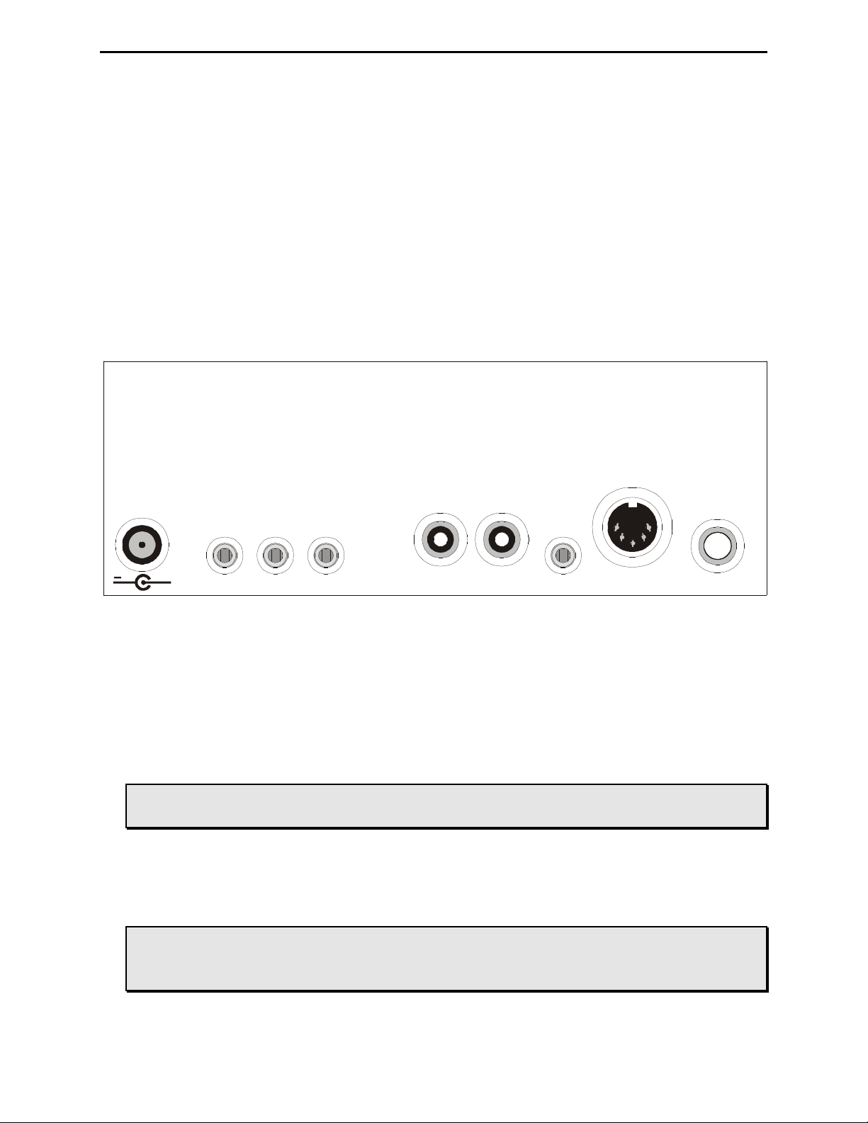
Figure 2: MFJ-464 Back Panel.
• Power: The Power jack accepts a 2.1 mm coaxial plug with positive center and negative
sleeve. This unit requires 12 volts DC. An optional 500 mA power supply, the MFJ-1315, is
available from MFJ Enterprises, Inc. This unit requires a minimum of 50 mA at no volume
and without using a keyboard and a maximum of 300 mA at maximum volume into an 8-ohm
audio load with a typical keyboard. It may require more current depending on the keyboard
used; typical keyboard uses about 100 mA.
WARNING: Do not apply voltages greater that 18 volts to this unit, or permanent
damage to the unit may result.
• Side Tone: The Side Tone is a 3.5 mm stereo phone jack for connecting to an external
speaker or headphones. This jack accepts both stereo and mono plugs. When this jack is
used, the internal speaker is disabled. An optional external speaker, the MFJ-281, is
available from MFJ Enterprises, Inc.
WARNING: To prevent suffering hearing damage when using headphones, turn the
Volume control to minimum before putting on the headphones and then
slowly adjust for a comfortable volume.
Page 8

MFJ-464 Instruction Manual CW Keyer/Reader
4
• Radio Spkr: The Radio Spkr is a 3.5 mm stereo phone jack for connecting to an external
speaker. This jack is normally a bypass of the Radio In jack. This jack accepts both stereo
and mono plugs.
• Radio In: The Radio In is a 3.5 mm stereo phone jack for connecting to the radio’s
headphones or line out. This jack accepts both stereo and mono plugs, but only the tip of the
plug is used.
• PTT Output: The PTT Output is an RCA jack providing connection for a PTT (push-to-
talk) output that goes low when active. This jack is an open-drain output; an external pull-up
can be used if so desired. Use a quality-shielded cable for connection to this jack.
• Keying Output: This unit supports only positive keyed radios (most solid-state radios). Use
a quality-shielded cable for connection to this RCA jack. Consult your transmitter's manual
to determine if it uses direct (positive) or grid-block (negative) keying. If your radio is
negative keyed, the transmitter will either not key at all or key continuously.
• Serial Port: The serial port on the back of the unit accepts a 3.5 mm stereo phone plug to a
standard 9-pin female plug for connecting the MFJ-464 to a computer for ASCII file transfers
or monitoring your sending on the computer screen. A 3.5 mm to DB9 serial cable, the MFJ5161, is available from MFJ Enterprises, Inc. If your computer has a 25-pin serial port, use a
9-pin-to-25-pin adapter. If you prefer you can make this cable using the following table:
Connect 3.5 mm Stereo Plug
To DB9 (female)
To DB25 (female)
Tip (TxD)
Pin 2
Pin 3
Ring (RxD)
Pin 3
Pin 2
Sleeve (GND)
Pin 5
Pin 7
To communicate with the MFJ-464, use a terminal program on your computer that is capable
of transferring information in ASCII format. Configure the software for 9600 baud, 8 data
bits, 1 stop bit and no parity; set the flow control to Xon/Xoff.
• Keyboard: The keyboard port accepts most standard AT style keyboards (XT keyboard
does not work with the MFJ-464). The MFJ-551 keyboard is guaranteed to be fully
compatible with the keyer and available from MFJ Enterprises, Inc.
Configuration of the keyboard operation is set in the Quick mode (see page 19). It allows
selection of whether a Qwerty or Dvorak keyboard is used (see Figures 3 and 4). The Repeat
feature selects whether or not to repeat a key when it is held down. The Caps Lock power on
status can also be selected. The factory defaults are Qwerty keyboard, Repeat off and Caps
Lock on.
• Key Input: The Key Input jack is a _-inch stereo phone jack. An iambic or single lever
(dual contact) paddle with a shielded cable should be used. When used with paddles, the dot
wire should be connected to the tip of the plug, the dash wire to the ring, and the ground wire
to the shield.
Page 9

MFJ-464 Instruction Manual CW Keyer/Reader
5
Figure 3: Qwerty Keyboard Layout.
Figure 4: Dvorak Keyboard Layout.
Connecting to a Computer
You may connect the MFJ-464 to a computer using the 9-pin DIN serial port on the back panel.
If your computer has a 25-pin serial port, you can use a 25-pin-to-9-pin adapter.
To use a computer with the MFJ-464, run a terminal program that will upload and download
ASCII files, and configure the terminal program to do so. Set the terminal program for 9600
baud, 8 data bits, one stop bit and no parity; set the flow control to Xon/Xoff. If you see
extraneous linefeeds on the computer screen when receiving data from the MFJ-464, you may
configure your software to strip out these extra linefeeds.
During sending, the characters sent by the MFJ-464 are sent through the serial port, so you may
use your computer to monitor the transmitted copy. You may find this particularly convenient.
You also may upload and download text files between the MFJ-464 and your computer. For
details on this, see the discussion of “Uploading and Downloading Messages” on page 33.
!
1
@
2 3
#
4
$
5
%
6
^
7
&
8
*
9
(
0
)
\
|
“
‘
F G L
=
+
A
D HS
-
_
:
;
J K
[
{
]
}PYR OE U ITQ W
<
, .
>C
/
?NX B MVZ
!
1
@
2 3
#
4
$
5
%
6
^
7
&
8
*
9
(
0
)
[
{
]
}
\
|
“
‘
<
, .
> P Y F G C R L
/
?
=
+
A
O E U I D H T N S
-
_
:
;
Q J K X B M W V Z
Page 10

MFJ-464 Instruction Manual CW Keyer/Reader
6
Basic Operation
The MFJ-464 is simple to operate. The Power button controls power to the unit. Start sending
with a paddle or keyboard. Adjust the volume and speed to your preference. If the speed is still
too fast or too slow, adjust the speed using the Set dial control.
All characters or code sent by the user are played on the sidetone speaker. This allows the user
to hear what he is keying, typing, or sending with a computer. Only when the keyer is used with
a paddle is the code sent as soon as it is keyed. When using a keyboard or keyer terminal, you
may type ahead of the code that is being transmitted. This allows you to enter words and phrases
faster than the transmitted code. This permits smoother code with less pauses because you can
fix misspelled words and think of the right phrase to use while your previous sentence is being
sent.
When you are in command mode, memory save, or configuration mode, the code sent to the
speaker is not sent to the Keying Output or your radio. This keeps all erroneous code off of the
air.
How to Use the Menu System
You may set up the MFJ-464 to perform any of its many functions by making the appropriate
selections from its menu system. This system consists of four main mode menus, 19 setup mode
menus and three quick mode menus. You make your selections using the five buttons under the
LCD display - Mode, MSG1/Prev, MSG2/Next, MSG3/100 and MSG4/1. These buttons do the
following:
• Mode - Scrolls through the main mode menus and setup mode menus when press briefly. To
enter the setup mode, press and hold this button for two seconds. To exit the setup mode,
press this button to go back to the main mode.
• MSG1/Prev - Play/program message 1 or go to the previous setup menu.
• MSG2/Next - Play/program message 2 or go to the next setup menu.
• MSG3/100 - Play/program message 3 or select step of 100 in setup mode.
• MSG4/1 - Play/program message 4 or select step of 1 in setup mode.
The main mode menus are arranged in a "wrap-around" structure, so that momentarily pressing
the Mode button will bring up another main menu in a sequence. Figure 5 shows the sequence of
the main mode menus. When power is turned on, the main menu displayed is the one that was
displayed when the unit was last turned off.
The setup mode menus are also arranged in a "wrap-around" structure, so that pressing the
Previous or Next button will bring up another setup menu in a sequence. Figure 5 shows the
sequence of the setup mode menus. When entering the setup mode, the setup menu displayed is
the one that was last used.
Page 11

MFJ-464 Instruction Manual CW Keyer/Reader
7
To see how the setup mode menus system works, consider the following example.
EXAMPLE: To enter the setup mode, press and hold the Mode button for two seconds.
If the display shows that you are in the Farnsworth menu, pressing the Next button would
put you in the Weight menu and pressing the Previous button would put you in the
Overall Speed menu. Adjusting the Set dial control would lower or raise the overall code
speed. Once you have selected the speed you desire, you may leave the setup mode by
pressing the Mode button again; or press Previous or Next button to go to another setup
menu.
Once you have made your choices within the setup mode, they will be saved in non-volatile
memory for your next session.
Page 12
MFJ-464 Instruction Manual CW Keyer/Reader
8
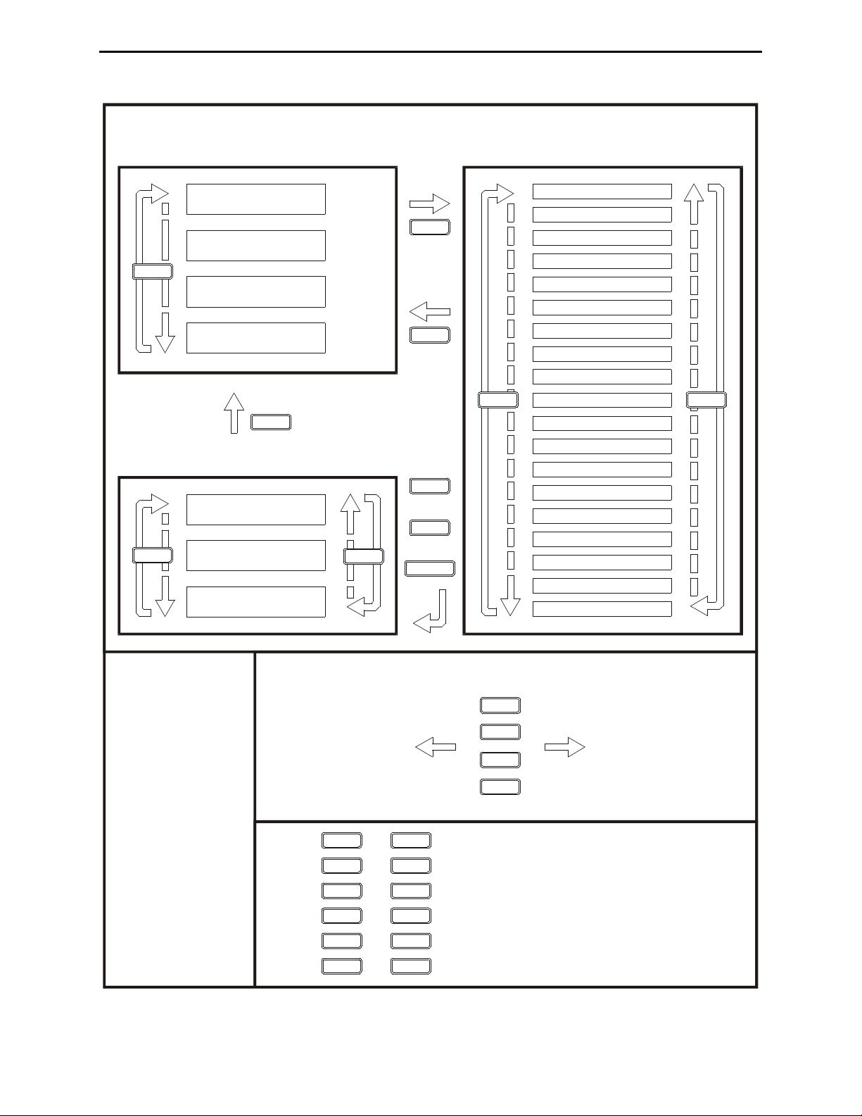
FLOW CHART
OVERALL SPEED
FARNSWORTH
WEIGHT
CHAR SPACE
WORD SPACE
KEY COMPENSATION
KEY DELAY
PTT HANG TIME
TONE
SERIAL NUMBER
LEADING ZEROES
OTHER ZEROES
NINES
IAMBIC
REVERSE
PADDLE
MONITOR
OUTPUT
QUEUE
SETUP MODESMAIN MODES
BUTTON
ACTION
Press + to decrement serial number.
Press + to increment serial number.
Press + to toggle repeat reader buffer.
Press + to toggle freeze reader buffer.
DIT
Press + to enter pulse tune mode.
DAH
Press + to enter carrier tune mode.
s13
w50
t70
00
MODE
PREVNEXT
For 2 sec.
MODE
MODE
MODE
MODE
MODE
MODE
MODE
MODE
MSG1
MSG2
MSG3
MSG4
For 2 sec.
MSG1
Program Message 1 Playback Message 1
Program Message 2 Playback Message 2
Program Message 3 Playback Message 3
Program Message 4 Playback Message 4
MSG2
MSG3
MSG4
Press
Speed
Weight
Tone
Reader
Speed
QUICK MODES
KEYBOARD LAYOUT
REPEAT
CAPS LOCK
MODE
MSG1
POWER
+
+
MODE
PREV
NEXT
Figure 5: MFJ-464 Flow Chart and Button Action Chart.
Page 13

MFJ-464 Instruction Manual CW Keyer/Reader
9
The Buttons
The Buttons
Mode Button [MODE]
The Mode button is used to change keyer mode. In the main mode, press Mode button to cycle
among Speed, Weight, Tone and Reader Speed menus. This button is also used to enter and exit
the setup mode, or used in combinations with other buttons and paddles to perform special
functions.
Message Buttons [MSG1] to [MSG4]
There are four messages buttons corresponding to the four messages. To play a message, press
and release the corresponding message button. To save a message, press and hold a message
button for two seconds until the keyer responds with “GO” (dah-dah-dit dah-dah-dah). You may
then key in a message using the paddle, keyboard or terminal. Press any message button to end
the message. Refer to “The Memory” section on page 35 for explanation of the MFJ-464’s
message memory.
Button Combinations
The Mode button can be pressed in combination with another button or paddle to perform special
functions. To do this, press and hold the Mode button, within two seconds press another button
or paddle, and then release both buttons and paddle.
Decrement [MODE] + [MSG1]
Press and hold the Mode button and within two seconds press the MSG1 button to decrement the
serial number by one, effectively canceling the automatic increment applied when last played
from a message. The decrement function accommodates re-sending the last serial number, as
might be needed when a repeat of a contest exchange is requested, or canceling the exchange
with a station that proved to be a “dupe”. The unit will echo a "D" (dah-di-dit) for every number
that is decrement. Decrement serial number 0001 rolls over to 9999, because the number 0000 is
not used.
Increment [MODE] + [MSG2]
Press and hold the Mode button and within two seconds press the MSG2 button to increment the
serial number by one. The unit will echo an "I" (di-dit) for every number that is increment.
Increment serial number 9999 rolls over to 0001, because the number 0000 is not used.
Repeat Reader Buffer [MODE] + [MSG3]
Press and hold the Mode button and within two seconds press the MSG3 button to repeat the
reader buffer.
Page 14

MFJ-464 Instruction Manual CW Keyer/Reader
10
Freeze Reader Buffer [MODE] + [MSG4]
Press and hold the Mode button and within two seconds press the MSG42 button to freeze the
reader buffer.
Pulse Tune [MODE] + [DIT]
Press and hold the Mode button and within two seconds tap the Dit paddle to engage the pulse
tune mode. The keyer will send a continuous string of pulses to tune your station. The rate
(speed of 50 to 99 WPM) and the duty cycle (weight of 1% to 35%) of the pulses can be adjusted
with the message buttons. Press MSG1 button to decrease speed and MSG2 button to increase
speed. Press MSG3 button to decrease weight and MSG4 button to increase weight. Press Mode
button, either paddle or the ESC key to exit.
Carrier Tune [MODE] + [DAH]
Press and hold the Mode button and within two seconds tap the Dah paddle to engage the carrier
tune mode. The keyer will key continuously to tune your station. Press any button, paddle or
key to exit.
Page 15

MFJ-464 Instruction Manual CW Keyer/Reader
11
The Menus
Main Mode Menus
The main mode menus allow you access to the commonly used functions. There are four main
mode menus arranged in a “wrap-around” structure. When power on, keyer operation starts with
the main menu that was last used. The four main menus give you easier access to the frequently
adjusted settings and display their current values. Within each main menu, press the Mode
button briefly to view the next main menu. Turn the Set dial control to change the setting of the
current menu. Press and hold the Mode button for two seconds to enter the setup mode (see
below).
Speed
This menu is placed in the main menus to allow easier access to change the overall speed in the
range of 5 to 99 WPM. When s## is displayed, turn the Set dial control to change the overall
sending speed. Note that setting the overall speed higher than or equal to the Farnsworth speed
will disable Farnsworth spacing.
Weight
This menu is placed in the main menu to allow easier access to change the weight of code
elements in the range of 25% to 75%. Weight is the duty cycle of a continuous string of dots,
which is 50% for perfect code. When w## is displayed, turn the Set dial control to change the
code weight. A higher weight produces a heavier sound, and a lower weight causes characters to
sound lighter.
Tone
This menu is placed in the main menu to allow easier access to change the audio frequency of the
sidetone in the range of 305 to 1006 Hz. When t## is displayed, turn the Set dial control to
change the sidetone frequency. Note the one’s digit is not displayed and 1006 Hz is displayed as
t99. Most people prefer 700 to 800 Hz sidetone.
Reader Speed
This menu shows the code speed of the incoming Morse code message as ### WPM.
Maximum reader speed that can be displayed is 127 WPM.
Setup Mode Menus
The setup mode menus allow you to set up how the MFJ-464 works and behaviors. There are 19
setup mode menus arranged in a “wrap-around” structure. To access these setup menus, press
and hold the Mode button for two seconds. The setup menu that will display is the one that was
last used. When finishing, press the Mode button again to go back to the main mode for normal
operation. The LED will blink to indicate that you are in the setup mode. The Keying Output
and PTT Output are also disabled.
Page 16

MFJ-464 Instruction Manual CW Keyer/Reader
12
Within each setup menu:
• Press the Mode button to exit the setup mode and go back to the main mode.
• Press the Next button to view the next setup menu; press the Previous button to view the
previous setup menu.
• Press the “100” button to set incremental step to 100; press the “1” button to set incremental
step to 1. This affects the Set dial control in the PTT Hang Time and Serial Number setup
menus.
• Turn the Set dial control to change the setting for that setup menu.
Overall Speed
The Overall Speed menu allows you to set the code speed in the range of 5 to 99 words per
minute (WPM). By "overall" speed, we mean the speed at which the words are sent. A "word"
is defined as 50 units of time, and the word "PARIS" is exactly 50 units in length. Therefore, if
"PARIS" is sent 13 times in one minute, the sending speed is 13 WPM. Standard Morse code
timing defines a dit as one unit of time and a dah as three units of time. Within each character,
there is one unit between elements (dits and dahs). Three units separate characters and seven
units separate words. Farnsworth spacing (see below) will increase the amount of time between
characters and words. Note that setting the overall speed greater than or equal to the Farnsworth
speed will disable Farnsworth spacing.
Farnsworth
The Farnsworth menu allows you to disable or enable Farnsworth mode and set the Farnsworth
speed (character speed) in the range of 10 to 99 WPM. When Farnsworth mode is enabled,
characters (dots, dashes, and intra-character spaces) are sent at the Farnsworth speed, but the
spacing between characters and words is increased to produce a slower overall speed. This
technique is useful for helping the novice learn the sounds of the code characters and avoid the
tendency of counting individual dots and dashes. The Farnsworth speed is always higher than
the overall speed. As a result, Farnsworth mode (if enabled) is automatically disabled when the
overall speed is changed to one that is greater than or equal to the current Farnsworth speed.
Also, Farnsworth speed cannot be enabled when the overall speed is at its maximum of 99 WPM.
Weight
The Weight menu is used to set the code weight in the range of 25% to 75%. Weight is the duty
cycle of a continuous string of dots, where 50% for perfect code. A higher weight produces a
heavier sound and a lower weight causes characters to sound lighter.
50% Weight
25% Weight
75% Weight
Figure 6: Code Weight.
Page 17

MFJ-464 Instruction Manual CW Keyer/Reader
13
Character Space
The Character Space menu is used to increase the character space (normally three units) up to 12
units long. There are two numbers on line two of the display; the number enclosed within “[“
and “]” is the character spacing and the other number is the word spacing. Note the character
space is always at least four units shorter than the word space. So you might have to increase the
word spacing before adjusting the character space.
Word Space
The Word Space menu is used to increase the word space (normally seven units) up to 16 units
long. There are two numbers on line two of the display; the number enclosed within “[“ and “]”
is the word spacing and the other number is the character spacing. Note the word space is
always at least four units longer than the inter-character space.
Keying Compensation
The Keying Compensation menu is used to increase the keying on-time and decrease the keying
off-time up to 25 milliseconds (ms). Some radios have a key delay of 5 ms or more. By setting
5 milliseconds of compensation, the keyer will add 5 ms to the dots and dashes and subtract 5 ms
from the intra-character spaces. Although similar to increasing weight, this adjustment is
independent of the speed. This setting is used primarily to correct keying distortion by certain
transceivers and to eliminate the problems with a transmitter key delay.
Keying Delay
The Keying Delay menu is used to delay the keying output up to 20 milliseconds. This setting is
used primarily to accommodate switching delay in certain station setup. It is used in conjunction
with the PTT line to delay the keying output until all the switching is finished; that is, the keying
output is lagged behind the sidetone audio and the PTT output. This controls the time between
when PTT is asserted and when CW keying will start.
PTT Hang Time
The PTT Hang Time menu is used to set the PTT hang time from 1 to 9999 milliseconds. This
controls the time between when CW keying is ended and when the PTT will de-assert. You may
adjust this to your liking for on-the-air sending. Press the “1” button and use the Set dial control
to change time in increments of 1 ms; press the “100” button and use the Set dial control to
change time in increments of 100 ms.
Note: If Keying Delay and PTT Hang Time are equal to zero, the PTT Output waveform will
be identical to the Keying Output waveform.
Page 18

MFJ-464 Instruction Manual CW Keyer/Reader
14
PTT Hang TimeKeying Delay
PTT Output
Keying Output
Sidetone Audio
Figure 7: Keying Delay and PTT Hang Time Timing.
Tone
The Tone menu allows you to set the audio frequency in the range of 305 to 1006 Hz. The MFJ464 features smooth, clean audio, with sine wave output, instead of the harsh square wave audio
used by many other keyers. Also, the MFJ-464 produces each dit and dah with a rise and decay
time of approximately 5 milliseconds, avoiding the "spikes" that cause distracting key clicks.
The MFJ-464's audio sounds like that of a good CW transceiver.
Keying Output
Sidetone Audio
Rise Time Decay Time
Figure 8: Rise Time and Decay Time Timing.
Page 19

MFJ-464 Instruction Manual CW Keyer/Reader
15
Serial Number
The Serial Number menu allows you to set the current serial number from 0001 to 9999. Press
the “1” button and use the Set dial control to change number in increments of 1; press the “100”
button and use the Set dial control to change number in increments of 100. Only three digits are
sent for numbers below 1000—use leading zeroes when appropriate. The serial number is
automatically post-incremented each time it is sent. Serial number 9999 will wrap-around to
0001, skipping 0000 since it is not used. Use Leading Zeroes, Other Zeroes and Nines menus to
control the way zeroes and nines in the serial number are sent (see below). There are a four-digit
number and three single characters on line two of the display. The four-digit number enclosed
within “[” and “]” is the serial number.
Leading Zeroes
The Leading Zeroes menu is used to set whether the leading zeroes in the serial number are sent
as “0”, “O”, “T” or not at all. There are a four-digit number and three single characters on line
two of the display. The character enclosed within “[” and “]” is the replacement for the leading
zeroes in the serial number.
Other Zeroes
The Other Zeroes menu is used to set whether the non-leading zeroes in the serial number are
sent as “0”, “O” or “T”. There are a four-digit number and three single characters on line two of
the display. The character enclosed within “[” and “]” is the replacement for the other zeroes in
the serial number.
Nines
The Nines menu is used to set whether the nines in the serial number are sent as “9” or “N”.
There are a four-digit number and three single characters on line two of the display. The
character enclosed within “[” and “]” is the replacement for the nines in the serial number.
Iambic
The Iambic menu allows you to enable or disable iambic operation. Iambic operation allows you
to squeeze both paddles and get alternating dots and dashes. There are two different types of
iambic keying, and both are available. The difference in behavior of these two modes occurs
when both paddles are squeezed and then released. In iambic A mode, the keyer will simply
complete the element (dot or dash) in progress, and then stop sending. In iambic B mode, the
keyer will complete the element in progress, and then send an additional opposite element. For
example, a release during the dash produces "dit-dah" (A) in iambic A mode but produces "ditdah-dit" (R) in iambic B mode. Non-iambic mode does not alternate between dots and dashes
during a squeeze. It plays whatever side made contact first until it is released. That is, when
iambic mode is disabled there are no dot and dash memories.
Page 20

MFJ-464 Instruction Manual CW Keyer/Reader
16
Reverse
The Reverse menu allows you to reverse the paddles designation. When using paddles, the MFJ464 normally expects the dot paddle to be connected to the tip of the plug and the dash paddle to
be connected to the plug's ring. If your paddles are wired in the opposite manner, or you wish to
change between right and left-handed operators, you may turn Reverse ON to switch the paddle
functions. You can also set this mode by simply pressing the paddle you desire to designate as
the dot paddle.
Paddle
The Paddle menu allows you to select how the paddle works. With the automatic option, the
keyer functions as an iambic keyer for use with a dual-lever paddle. As an iambic keyer, the
MFJ-464 has dot and dash memories, for "squeeze keying," and functions just like other iambic
keyers, both standalone keyers and those built into radios. With the semi-auto option, the keyer
can be used with a single-lever key, with dots generated automatically and dashes formed
manually by the user. This emulates the function of a mechanical semi-automatic "bug." You
also may use this unit with a straight key or a bug, connect the straight key or bug to the ground
and the dash line. With the hand-key option, both the dot and dash lines can be used to connect
to a straight key. Notice hand-key mode may not be used to enter messages or setup commands.
Note: In hand-key mode using the paddle, the MFJ-464 will not display the code sent or
record to the keyer memory. Also, the difference between this and the Handkey
command is that this command affects the paddle only.
Monitor
The Monitor menu is used to toggle the sidetone speaker on and off. If the sidetone is turned off,
it will still play command messages and status information. To conserve power, the keyer
should be operated with the monitor off in favor of the rig’s sidetone.
Output
The Output menu is used to toggle the keying output on and off. If the output is turned off, no
signal goes to the Keying Output or the PTT Output to allow practice operation. The output is
temporarily disabled during memory message storing, command mode operation, status
information, and keyer setup.
Queue
The Queue menu is used to toggle the message queue on and off. Queue mode enables the user
to load messages into a buffer to play sequentially. In queue mode, if you press a message
button while a message is playing, that message will play after the current message is done.
When queue mode is off, pressing a message button will abort any message being played and
play the new message. When on, up to eight button presses are stored in order and acted upon in
succession as each message is completed.
Note: Disabling the queue mode increases the message stack size to seven levels deep used by
the embedded Call command.
Page 21

MFJ-464 Instruction Manual CW Keyer/Reader
17
The Reader
Using the MFJ-464 CW Reader
The MFJ-464 comes complete with a CW Reader. The CW Reader on the MFJ-464 is a Morse
code decoder that is displayed on a two-line 32-character LCD (liquid crystal display). It can
auto-track CW up to 99 WPM (words per minute), and has a volatile repeat buffer memory of
140 characters.
The Reader on the MFJ-464 functions in two different ways. It decodes and displays the Morse
code being sent and the Morse code being received. The LCD screen displays on the first
(upper) line the code that is being sent and on the second (lower) line the code that is being
received.
Operation
Connect the proper cables from the MFJ-464 to your radio. If you cannot remember where the
cables properly go, then see the Back Panel section of the manual on page 3. Power on your
receiver and tune it to find a clear, well-sent Morse code signal. When you have found one,
power on the MFJ-464. If necessary, adjust the Input Level control on your radio so that the
Lock LED is blinking. Now tune in the signal again on your radio to adjust its frequency (to
match the PLL frequency) until you get the maximum response from the LED. Next, turn the
Input Level control on your radio until the LED is blinking in sync with the Morse code. Wait
for the LCD screen to start displaying something that makes sense. Once it has tracked the
signal, read the messages as they scroll across the LCD screen. Repeat these steps a few times to
get the best response.
IMPORTANT: You can adjust the Input Level and Tune the signal directly on the MFJ-464.
However, it is recommended that you do these adjustments on your radio and
not on the MFJ-464. Changing the Input Level and the Tuning the signal on
the MFJ-464 can cause problems when trying to listen to another signal.
These adjustments are much easier to do on your radio than on the unit itself.
The Reader automatically locks on and tracks low and high speed Morse code, decoding it up to
99 WPM. When the unit is locked the green LED labeled LOCK will light. Its initial power-on
tracking speed is 20 WPM. It will take some time to track an incoming signal or to re-track an
extremely slow signal after copying a fast one and vice versa. If there is a lot of static, it will
take time to track slow signals. This is because the static appears to the Reader as high speed
Morse code.
There is a lot of sloppy code on the air and most computers cannot read them. Do not expect this
Reader to do the incredible when it comes to copying Morse code. Nothing can clean up and
copy a sloppy fist, especially with a weak signal and lots of QRM/QRN (interferences).
However, you will be quite pleased when copying strong well-sent code, especially those sent
with electronic keyers. Farnsworth code* and extremely negative weighted code will display
with spaces between each character. Finally, invalid characters are displayed as block characters
on the LCD screen and as spaces on the computer monitor. Prosigns (procedural signs) are
enclosed within “<” and “>” such as <AR> and <SN>.
Page 22

MFJ-464 Instruction Manual CW Keyer/Reader
18
The Paddle
Using the MFJ-464 with a Paddle
Plug an iambic or single lever paddle into the Key Input jack of the MFJ-464. A _-inch stereo
phone plug and a two-conductor shielded cable should be used. If separate shielded cables are
used, the two shields should be tied together and connected to ground. The dot wire should be
connected to the tip of the plug and the dash wire to the ring. Begin sending code using the
paddles. If you would like to change speed, sidetone or weight, see the sections pertaining to
these commands.
The iambic paddle has a unique feature that the single lever paddle does not have. Notice that
the two paddles are independent and can be squeezed together. Both the dot and dash contacts
touch the chassis, therefore ground. The MFJ-464 senses this happen and uses it as a separate
keying mode.
Iambic keying has two modes: A and B. When a squeeze is released during an element (dot or
dash), iambic B adds an opposite element. Iambic A just finishes the element in progress and
does not produce a following alternate element.
The dot and dash memories make sending easier. The memories allow the user to key a dot
before the completion of a dash and vice versa. This feature can be checked by setting the keyer
to the lowest speed and tapping first the dash lever and then the dot lever before the completion
of the dash. The keyer will provide both the dash and the dot. The dash memory can be checked
in a similar manner. The dot insertion feature allows the user to insert a dot by tapping the dot
lever while holding the dash lever in. The dash insertion feature allows the user to insert a dash
while holding the dot lever in. The iambic operation allows sending alternate dots and dashes
when both levers are squeezed. The first lever contacted will determine whether a dot or dash
occurs first.
Note: It is recommended the Farnsworth mode be disabled when sending with the paddle.
When Farnsworth mode is enabled, the paddle will send code at the Farnsworth speed,
not the overall speed.
Page 23

MFJ-464 Instruction Manual CW Keyer/Reader
19
Message Memory
To play a message, press and release the corresponding message button MSG1 to MSG4. The
message will play and send to your radio. To save a message to memory, press and hold a
message button for two seconds until the keyer plays "GO" (dah-dah-dit dah-dah-dah) in Morse
code. You may now key in a message using the paddle.
Begin keying your message. As you pause after every word, the keyer will insert a word break.
If the keyer does not recognize your code as a valid character, the keyer will display a block
character and that character will not be saved. Continue keying in the rest of the word.
If you make a mistake entering a word, you can back up over it by keying in at least 10
continuous dots. The keyer will erase the previous word. Also, press the Mode button
momentarily will delete the last character; press and hold the Mode button for two seconds will
delete the last word.
At the end of your message, press and hold any of the four message buttons for two seconds to
end your message. The keyer will respond by sending an end-of-message character (di-dah-didah-dit) and automatically insert “]” to the end of your message.
Refer to “The Memory” section on page 35 for explanation of the MFJ-464’s message memory
and how to use the embedded commands to enhance your message.
Page 24

MFJ-464 Instruction Manual CW Keyer/Reader
20
The Keyboard
Using the MFJ-464 with a Keyboard
Quick Mode
The quick mode menus allow you to set up how the keyboard works and behaviors. There are
three quick mode menus arranged in a “wrap-around” structure. To access these quick menus,
press and hold both the Mode and MSG1 buttons while turning the power on. The quick menu
that will display is the one that was last used. When finishing, press the Mode button to go to the
main mode for normal operation.
Within each quick menu:
• Press the Mode button to exit the quick mode and go to the main mode.
• Press the Next button to view the next quick menu; press the Previous button to view the
previous quick menu.
• Turn the Set dial control to toggle the setting for that quick menu.
Keyboard Layout
The Keyboard Layout menu set the type of keyboard to be used. The MFJ-464 can be used with
either a Qwerty or a Dvorak keyboard.
Repeat
The Repeat menu set whether or not to repeat a key when it is held down.
Caps Lock
The Caps Lock menu set the power-on Caps Lock status of the keyboard.
Keyboard Operation
When you plug in a standard IBM style AT keyboard, your keyer becomes a powerful keyboard
keyer. The MFJ-464 uses the letter keys A-Z, the number keys 0-9, the function keys F1-F12,
the space bar, the arrow keys, and the punctuation characters that have Morse equivalents.
Prosigns have been assigned to some of the other punctuation characters for quick operation.
See the appendix “Morse Code Character Set” on page 43.
The operation of the keyboard is simple. Begin typing on the keyboard. Typed characters are
sent at the code speed of the keyer. If a typing mistake occurs, the BACK SPACE key can be
pressed to erase the last character before it is sent. If you want to purge all the text in the buffer
that has not yet been sent, press the ESC key. Pressing PAUSE during transmission stops
playback of the buffer text and allows entry with the paddle; press ESC once resumes playback
of the buffer text from where it was interrupted (pressing ESC twice will abort the message
playback).
Page 25

MFJ-464 Instruction Manual CW Keyer/Reader
21
When typing speed is greater than the code speed, characters will begin to fill a type-ahead
buffer. The code sent to the radio and over the sidetone speaker will lag behind the typing of
each character. Most of the time this will not cause a problem. Only for very fast typists that
send slow code will the type ahead buffer fill significantly. The maximum size of the type-ahead
buffer is 190 characters. When the buffer fills to 180 characters, the sidetone will be higher.
This is a signal to slow typing speed because when the buffer fills to 190 characters each new
key-press will be lost. It is best to never type much faster than your code speed.
Transmitted characters and buffer memory may be monitored using the LCD display on the
MFJ-464. This readout is comprised of two lines of text, each containing 16 characters. The top
line shows the characters currently being transmitted. The bottom line normally shows the
received characters. The bottom line can show the content of the type-ahead buffer memory; this
buffer line is toggled on and off with the PRINT SCREEN key. Note that non-ASCII characters,
such as CTRL, ALT, SHIFT, etc., are displayed as a block character on the buffer line.
If you want to send a special prosign, you can enclose it in “<” and “>”. To make a special
prosign, begin the prosign with “<”, type the characters of the prosign, and end the prosign with
“>”. For example, to make the prosign SN types < SN>. This will remove the inter-character
spaces between the characters making it a prosign. Any prosign can be made this way, even
special local prosigns. Another method is to enclose the prosign with backslashes such as \SN\.
An easier way to send special prosign is press ALT key, type the characters of the prosign, and
then release the ALT key (this method does not work within the terminal program as the ALT
key is reserved for other functions).
Note: The open angle bracket “<” enables prosign mode and the close angle bracket “>”
disables prosign mode; while the backslash “\” toggles the prosign mode on and off. In
addition, pressing the ALT key enables prosign mode and releasing disables it. A word
space also disables prosign mode.
Page 26

MFJ-464 Instruction Manual CW Keyer/Reader
22
Keyboard Key Combinations
Press a modifier key (CTRL, ALT or SHIFT) in combination with another key to perform special
functions or shortcuts. Note that these key combinations do not work in the Terminal mode,
because these modifier keys are reserved for the computer uses.
Key
Normal
Shift
Alt
Ctrl
A
aACustom Prosign
B
bBCustom Prosign
C
cCCustom Prosign
Set Character Space
D
dDCustom Prosign
Decrement Number
E
eECustom Prosign
F
fFCustom Prosign
Set Farnsworth
G
gGCustom Prosign
Set Word Space (Gap)
H
hHCustom Prosign
Hand Key
I
iICustom Prosign
Set Iambic
J
jJCustom Prosign
Set Hang Time
K
kKCustom Prosign
Set Key Compensation
L
lLCustom Prosign
Set Key Delay (Lag)
M
mMCustom Prosign
Set Monitor
N
nNCustom Prosign
Set Number
O
oOCustom Prosign
Set Output
P
pPCustom Prosign
Set Paddle
Q
qQCustom Prosign
Set Queue
R
rRCustom Prosign
S
sSCustom Prosign
Set Speed
T
tTCustom Prosign
Set Tone
U
uUCustom Prosign
V
vVCustom Prosign
Reverse
W
wWCustom Prosign
Set Weights
X
xXCustom Prosign
Carrier Tune (Xmit)
Y
yYCustom Prosign
Pulse Tune
Z
zZCustom Prosign
Set Zeroes & Nines
F1
Play Message 1
Program Message 1
F2
Play Message 2
Program Message 2
F3
Play Message 3
Program Message 3
F4
Play Message 4
Program Message 4
F5
Decrement Number
F6
Increment Number
F7
Repeat Reader Buffer
F8
Freeze Reader Buffer
F9
Get Quick Speed 1
Set Quick Speed 1
F10
Get Quick Speed 2
Set Quick Speed 2
F11
Get Quick Speed 3
Set Quick Speed 3
F12
Get Quick Speed 4
Set Quick Speed 4
Page 27

MFJ-464 Instruction Manual CW Keyer/Reader
23
Key
Normal
Shift
Alt
Ctrl
fl LEFT
Decrease Setting
Tone –1 Step
Weight –1%
Speed –1 WPM
‡ RIGHT
Increase Setting
Tone +1 Step
Weight +1%
Speed +1 WPM
‚ DOWN
Decrease Setting
Tone –5 Step
Weight –5%
Speed –5 WPM
· UP
Increase Setting
Tone +5 Step
Weight +5%
Speed +5 WPM
ESC
Abort/Cancel/Exit
BACK SPACE
Delete Character
Delete Word
ENTER
End Message
PRINT SCREEN
Display Type Ahead
Buffer
SCROLL LOCK
Freeze Reader Buffer
PAUSE
Pause
~
Enter setup command mode
\
Toggle prosign mode
<
Decrease setting or enable prosign mode
>
Increase setting or disable prosign mode
[
Use the close square bracket “]” to end message allowing carriage returns in messages
]
End message if selected by the open square bracket “[”
Note: The · (UP), ‚ (DOWN), fl (LEFT), and ‡ (RIGHT) keys are referred to as the Arrow
keys in this manual.
Setup Commands
Press the tilde “~” key to enter command mode and the keyer responds with “CO” (dah-di-dahdit dah-dah-dah). Enter a setup command. If the command is invalid then the keyer will send an
error character (di-di-di-di-di-di-di-dit) and return the keyer to normal mode. If the user wishes
to re-attempt modifying features using command mode, he must re-enter command mode by
pressing “~” key again. If you enter the command mode accidentally, press ESC key to exit. At
any time, press ENTER to accept and exit or press ESC to cancel and exit. Alternately, pressing
CTRL+Key to directly enter the command mode; that is, CTRL+S is the same as “~S”. To
perform this action, press and hold the CTRL key, press a letter key B to Z, and then release the
CTRL key. Refer to the appendix “Setup Commands” on page 46 for a table of these
commands.
C# Character space – increases the inter-character space with # standard intra-character
spaces, where # is a single digit from 0 to 9. This allows the normally three-unit long
inter-character space up to 12 units long. Note the inter-character space is always at
least four units shorter than the word space. Therefore, you might have to increase
the word spacing before adjusting the character space.
Press LEFT or DOWN to decrease or press RIGHT or UP to increase the character
spacing, or enter one digit 0 to 9 to set the character spacing. Press ENTER to accept
and exit, or press ESC to cancel and exit.
Page 28

MFJ-464 Instruction Manual CW Keyer/Reader
24
D Decrement – decrements the serial number by one, effectively canceling the
automatic increment applied when last played from a message. The decrement
function accommodates re-sending the last serial number, as might be needed when a
repeat of a contest exchange is requested, or canceling the exchange with a station
that proved to be a “dupe”. The unit will echo a "D" (dah-di-dit) for every number
that is decrement. Decrement serial number 0001 rolls over to 9999, because the
number 0000 is not used.
F## Farnsworth – uses to enable Farnsworth mode and spacing. Farnsworth spacing adds
more time between characters to slow down the overall sending speed. The
advantage of this is that, by hearing the characters sent at a faster speed, you learn to
recognize each character by its distinctive rhythm, rather than by trying to "count
dits." This greatly assists you in copying Morse code at higher speeds. The
Farnsworth speed, however, must be higher than the overall speed. Setting ## to 00
or less than or equal to the overall speed will disable Farnsworth mode.
Press LEFT or DOWN to decrease or press RIGHT or UP to increase the speed, or
enter two digits 10 to 99 to set the Farnsworth speed or 00 to turn off Farnsworth
mode. Press ENTER to accept and exit, or press ESC to cancel and exit
Note: It is recommended the Farnsworth mode be disabled when sending with the
paddle. When Farnsworth mode is enabled, the paddle will send code at the
Farnsworth speed, not the overall speed.
G# Gap (word space) – increases the word space with # standard intra-character spaces,
where # is a single digit from 0 to 9. This allows the normally seven-unit long word
space up to 16 units long. Note the word space is always at least four units longer
than the inter-character space.
Press LEFT or DOWN to decrease or press RIGHT or UP to increase the word
spacing, or enter one digit 0 to 9 to set the word spacing. Press ENTER to accept and
exit, or press ESC to cancel and exit.
H Hand key – enters the hand key mode to use the SPACE key as a hand (straight) key.
The keyer responds with "HK" (di-di-di-dit dah-di-dah). Dots and dashes are made
manually by using the space bar on your keyboard. That is, keying follows closure of
the dot or dash paddle or the SPACE key, allowing hand-sent code. Normal keyer
operation is regained by squeezing both paddles or by pressing the ESC key.
I# Iambic – enables iambic A or B mode where # represents A or B, or disables iambic
operation with # = N. The keyer will respond with "A" (di-dah), "B" (dah-di-di-dit),
or "OFF" (dah-dah-dah di-di-dah-dit di-di-dah-dit). Press ESC to cancel and exit.
J#### PTT hang time – sets the PTT (push-to-talk) hang time to #### millisecond, where
#### represents four digits in the range of 0001 to 9999. This controls the time
between when CW keying is ended and when the PTT will de-assert. You may adjust
this to your liking for on-the-air sending.
Press LEFT or DOWN to decrease or press RIGHT or UP to increase the hang time,
or enter up to four digits 0001 to 9999 to set the hang time. Press ENTER to accept
and exit, or press ESC to cancel and exit.
Page 29

MFJ-464 Instruction Manual CW Keyer/Reader
25
K## Keying compensation – sets the keying compensation to ## millisecond, where ##
represents two digits in the range of 00 to 25. Some radios have a key delay of 5 ms
or more. By entering K05, the keyer will add 5 ms to the dots and dashes and
subtract 5 ms from the intra-character spaces. Although similar to increasing weight,
this adjustment is independent of the speed. This setting is used primarily to correct
keying distortion by certain transceivers and to eliminate the problems with a
transmitter key delay.
Press LEFT or DOWN to decrease or press RIGHT or UP to increase the
compensation, or enter up to two digits 00 to 25 to set the compensation time. Press
ENTER to accept and exit, or press ESC to cancel and exit.
L## Lag (keying delay) – sets the keying delay to ## millisecond, where ## represents two
digits in the range of 00 to 20. This setting is used primarily to accommodate
switching delay in certain station setup. It is used in conjunction with the PTT line to
delay the keying output until all the switching is finished; that is, the keying output is
lagged behind the sidetone audio and the PTT output. This controls the time between
when PTT is asserted and when CW keying will start.
Press LEFT or DOWN to decrease or press RIGHT or UP to increase the delay, or
enter up to two digits 00 to 20 to set the delay time. Press ENTER to accept and exit,
or press ESC to cancel and exit.
M# Monitor – enables (#=Y) or disables (#=N) the sidetone monitor, or toggles the
sidetone monitor on or off without the #. If the sidetone is turned off, it will still play
command messages and status information. To conserve power, the keyer should be
operated with the monitor off in favor of the rig’s sidetone.
To change Monitor mode type “~M” followed by “Y’ for on, “N” for off, or ENTER
to toggle. The keyer will respond with “ON” or “OFF”. Press ESC or any other key
to cancel and exit.
N#### Number – sets the serial number. The serial number can be set from 0000 to 9999
(0000 will be converted to 0001). Enter up to four digits to set the current serial
number and press ENTER to accept and exit, or press ESC to cancel and exit.
O# Output – enables (#=Y) or disables (#=N) the keying output, or toggles the keying
output on or off without the #. If the output is turned off, no signal goes to the
Keying Output or the PTT Output to allow practice operation. The output is
temporarily disabled during memory message storing, command mode operation,
status information, and keyer setup.
To change Output mode type “~O” followed by “Y’ for on, “N” for off, or ENTER to
toggle. The keyer will respond with “ON” or “OFF”. Press ESC or any other key to
cancel and exit.
Page 30

MFJ-464 Instruction Manual CW Keyer/Reader
26
P# Paddle – selects paddle mode of automatic (#=A), semi-automatic (bug, #=S) or
hand-key (#=H) mode. With the automatic option, the keyer functions as an iambic
keyer for use with a dual-lever paddle. As an iambic keyer, the MFJ-464 has dot and
dash memories for "squeeze keying" and functions just like other iambic keyers, both
standalone keyers and those built into radios. With semi-auto, the keyer can be used
with a single-lever key, with dots generated automatically and dashes formed
manually by the user. This emulates the function of a mechanical semi-automatic
"bug." You also may use this unit with a straight key or a bug, connect the straight
key or bug to the ground and the dash line. With the hand-key option, both the dot
and dash lines can be used to connect to a straight key. Notice hand-key mode may
not be used to enter messages or commands.
Note: In hand-key mode using the paddle, the MFJ-464 will not display the code
sent or record to the keyer memory. Also, the difference between this and
the Hand-key command is that this command affects the paddle only.
Q# Queue – enables (#=Y) or disables (#=N) the message queue, or toggles the message
queue on or off without the #. Queue mode enables the user to load messages into a
buffer to play sequentially. In queue mode, if you press a message button while a
message is playing, that message will play after the current message is done. When
queue mode is off, pressing a message button will abort any message being played
and play the new message. When on, up to eight button presses are stored in order
and acted upon in succession as each message is completed.
To change Queue mode type “~Q” followed by “Y” for on, “N” for off, or ENTER to
toggle. The keyer will respond with “ON” or “OFF”. Press ESC or any other key to
cancel and exit.
Note: Disabling the queue mode increases the message stack size to seven levels
deep used by the embedded Call command.
S## Speed – sets the overall code speed to ## WPM, where ## represents two digits in the
range of 05 to 99. By "overall" speed, we mean the speed at which the words or
groups are sent. A "word" is defined as 50 units of time, and the word "PARIS" is
exactly 50 units in length. Therefore, if "PARIS" is sent 13 times in one minute, the
sending speed is 13 wpm.
Standard Morse code timing defines a dit as one unit of time and a dah as three units
of time. Within each character, there is one unit between elements (dits and dahs).
Three units separate characters and seven units separate words. Farnsworth spacing
(see above) will increase the amount of time between characters and words. Note that
setting the overall speed greater than or equal to the Farnsworth speed will disable
Farnsworth spacing.
Press LEFT or DOWN to decrease or press RIGHT or UP to increase the code speed,
or enter up to two digits 05 to 99 to set the code speed. Press ENTER to accept and
exit, or press ESC to accept and exit.
Page 31

MFJ-464 Instruction Manual CW Keyer/Reader
27
T## Tone – sets the sidetone frequency to approximately ##0 Hz, where ## represents
two digits in the range of 30 to 99. The MFJ-464 features smooth, clean audio, with
sine wave output, instead of the harsh square wave audio used by many other keyers.
Also, the MFJ-464 produces each dit and dah with a rise and decay time of
approximately five milliseconds, avoiding the "spikes" that cause distracting key
clicks. The MFJ-464's audio sounds like that of a good CW transceiver.
Notice an alternating series of dots and dashes are sent to the sidetone monitor to
assist in the setting of the desired sidetone frequency. Press LEFT or DOWN to
decrease or press RIGHT or UP to increase the tone frequency, or enter two digits 30
to 99 to set the tone frequency. Press ENTER to accept and exit, or press ESC to
cancel and exit.
V reVerse – reverses the sense of the dot and dash paddles. When using paddles, the
MFJ-464 normally expects the dot paddle to be connected to the tip of the plug and
the dash paddle to be connected to the plug's ring. If your paddles are wired in the
opposite manner, or you wish to change between right and left-handed operators, you
may reverse the paddles.
W## Weight – sets the code weighting to ## percent, where ## represents two digits in the
range of 25 to 75. Weight is the duty cycle of a continuous string of dots, where 50%
for perfect code. A higher weight produces a heavier sound and a lower weight
causes characters to sound lighter.
An alternating dot/dash is produced to aid in changing the weight. Press LEFT or
DOWN to decrease or press RIGHT or UP to increase the weight, or enter two digits
25 to 75 to set the weight. Press ENTER to accept and exit, or press ESC to cancel
and exit.
X Xmit (carrier tune) – gives continuous key-down for adjusting transmitter or antenna
tuner. Press any key to exit and release the key line.
Y Pulse tune – gives continuous adjustable pulses for adjusting transmitter or antenna
tuner. Press MSG1 and MSG2 buttons to change the speed in the range of 50 to 99
WPM. Press MSG3 and MSG4 buttons to change the weight (duty cycle) in the
range of 1% to 35%. Press ESC to exit and release the key line.
Alternately, use CTRL+Arrow keys to change the pulse speed and ALT+Arrow keys
to change the pulse weight.
Z### Zeros and nines – sets the way zeros and nines in the serial number are sent. The first
# sets whether to send the leading zeros as "0", "O", "T" or not at all (# = "N"). The
second # sets whether the other zeros are sent as "0", "O" or "T". The last # sets
whether the nines are sent as "9" or "N". For example, "ZO09" will send the leading
zeros as "O" (dah-dah-dah), the other zeros as "0" (dah-dah-dah-dah-dah), and the
nines as "9" (dah-dah-dah-dah-dit).
# Play message – play message #, where # is the message number 1 to 4. Alternately,
press F1 to F4 to play the corresponding message.
># Save message – save message into the keyer memory #, where # is the message
number 1 to 4. Alternately, press CTRL+F1 to CTRL+F4 to save messages.
<# View message – view message #, where # is the message number 1 to 4.
Page 32

MFJ-464 Instruction Manual CW Keyer/Reader
28
Message Memory
With the keyboard, you can play or save messages using the keyboard function keys. To play a
message, press any keyboard function key F1 to F4. The message will play and send to your
radio. Press CTRL+Arrow keys to change the overall speed on the fly, press ALT+Arrow keys
to change the weight on the fly, and press SHIFT+Arrow keys to change the tone on the fly.
To save a message to memory, press and hold the CTRL key, press the keyboard function key F1
to F4, and then release the CTRL key (this is denoted as CTRL+Fn). The keyer will respond
with "GO" (dah-dah-dit dah-dah-dah). Now a message can be typed into memory.
Begin typing in your message pressing the space bar between words. The keyer echoes each
character as it is typed. Press the BACK SPACE key to delete the last character. In message
program mode only, press CTRL+BACK SPACE to delete the last word.
At the end of your message, press ENTER to end your message. The keyer will respond by
sending an end-of-message character (di-dah-di-dah-dit) and save your message. It will
automatically insert “]” to the end of your message.
If you accidentally enter “[“ during the message, you will have to use “]” to end your message –
this allows carriage returns (produced by ENTER) in the message. The open square bracket “[”
tells the keyer to replace the ENTER key with the close square bracket “]” as the end-of-message
key.
Refer to “The Memory” section on page 35 for explanation of the MFJ-464’s message memory
and how to use the embedded commands to enhance your message.
Quick Speeds
There are four pre-set memories to store the overall speed, so the speed can be quickly changed
during an exchange. This works similar to your car radio’s pre-set station memories. To store
the current overall speed into one of these pre-set memories, press CTRL+F9 to CTRL+F12. To
recall a pre-set speed to use as the current speed, press F9 to F12.
Page 33

MFJ-464 Instruction Manual CW Keyer/Reader
29
The Terminal
Using the MFJ-464 with a Terminal Program
The Keyer Terminal mode allows a computer to talk to your MFJ-464. All code sent from the
paddle and keyboard is echoed to the Keyer Terminal. All commands are accessible through the
Keyer Terminal.
Your computer will need a terminal program to talk to the keyer. The program should be
capable of uploading and downloading ASCII text files. Any good commercial or freeware
terminal program should be satisfactory for use with this keyer.
After you have connected the MFJ-464 to the serial port of your computer with the correct cable,
turn on your computer and load your terminal program. Set the baud rate to 9600, data bits to 8,
parity to none, and stop bits to 1. Also, set the flow control to Xon/Xoff. Now turn on your
MFJ-464. You should type something on the computer. Whatever you type should appear on
the LCD display, which shows that everything is working properly between the computer and
keyer. If you do not, recheck your terminal program and serial port cable connection.
You are ready to send with the keyer. To make a special prosign with the keyer terminal, begin
the prosign with "<" and end the prosign with ">". For example, to make the prosign SN types
<SN>. This will remove the inter-character spaces between the characters making it a prosign.
Any prosign can be made this way, even special local prosigns. Another method is to enclose
the prosign with backslashes such as \SN\.
Note: The open angle bracket “<” enables prosign mode and the close angle bracket “>”
disables prosign mode; while the backslash “\” toggles the prosign mode on and off. A
word space also disables prosign mode.
Tip: All keystrokes and commands from the Keyer Terminal can also be used via the
Keyboard.
Setup Commands
Press the tilde “~” key to enter command mode and the keyer responds with “CO” (dah-di-dahdit dah-dah-dah). Enter a setup command. If the command is invalid then the keyer will send an
error character (di-di-di-di-di-di-di-dit) and return the keyer to normal mode. If the user wishes
to re-attempt modifying features using command mode, he must re-enter command mode by
pressing “~” key again. If you enter the command mode accidentally, press ESC key at any time
to exit. At any time, press ENTER to accept or ESC to cancel. Refer to the appendix “Setup
Commands” on page 46 for a table of these commands.
Page 34

MFJ-464 Instruction Manual CW Keyer/Reader
30
C# Character space – increases the inter-character space with # standard intra-character
spaces, where # is a single digit from 0 to 9. This allows the normally three-unit long
inter-character space up to 12 units long. Note the inter-character space is always at
least four units shorter than the word space. Therefore, you might have to increase
the word spacing before adjusting the character space.
Press either the “<” or “>” to decrease or increase character spacing, or enter one digit
0 to 9 to set the character spacing. Press ENTER to accept and exit, or press ESC to
cancel and exit.
D Decrement – decrements the serial number by one, effectively canceling the
automatic increment applied when last played from a message. The decrement
function accommodates re-sending the last serial number, as might be needed when a
repeat of a contest exchange is requested, or canceling the exchange with a station
that proved to be a “dupe”. The unit will echo a "D" (dah-di-dit) for every number
that is decrement. Decrement serial number 0001 rolls over to 9999, because the
number 0000 is not used.
F## Farnsworth – uses to enable Farnsworth mode and spacing. Farnsworth spacing adds
more time between characters to slow down the overall sending speed. The
advantage of this is that, by hearing the characters sent at a faster speed, you learn to
recognize each character by its distinctive rhythm, rather than by trying to "count
dits." This greatly assists you in copying Morse code at higher speeds. The
Farnsworth speed, however, must be higher than the overall speed. Setting ## to 00
or less than or equal to the overall speed will disable Farnsworth mode.
Press either the “<” or “>” to decrease or increase speed, or enter two digits 10 to 99
to set the Farnsworth speed or 00 to turn off Farnsworth mode. Press ENTER to
accept and exit, or press ESC to cancel and exit
Note: It is recommended the Farnsworth mode be disabled when sending with the
paddle. When Farnsworth mode is enabled, the paddle will send code at the
Farnsworth speed, not the overall speed.
G# Gap (word space) – increases the word space with # standard intra-character spaces,
where # is a single digit from 0 to 9. This allows the normally seven-unit long word
space up to 16 units long. Note the word space is always at least four units longer
than the inter-character space.
Press either the “<” or “>” to decrease or increase word spacing, or enter one digit 0
to 9 to set the word spacing. Press ENTER to accept and exit, or press ESC to cancel
and exit.
H Hand key – enters the hand key mode to use the SPACE key as a hand (straight) key.
The keyer responds with "HK" (di-di-di-dit dah-di-dah). Dots and dashes are made
manually by using the space bar on your keyboard. That is, keying follows closure of
the dot or dash paddle or the SPACE key, allowing hand-sent code. Normal keyer
operation is regained by squeezing both paddles or by pressing the ESC key.
Tip: The space bar on the keyer terminal does not work properly in hand-key
mode, because of the typematic delay of the computer keyboard.
Page 35

MFJ-464 Instruction Manual CW Keyer/Reader
31
I# Iambic – enables iambic A or B mode where # represents A or B, or disables iambic
operation with # = N. The keyer will respond with "A" (di-dah), "B" (dah-di-di-dit),
or "OFF" (dah-dah-dah di-di-dah-dit di-di-dah-dit). Press ESC to cancel and exit.
J#### PTT hang time – sets the PTT (push-to-talk) hang time to #### millisecond, where
#### represents four digits in the range of 0001 to 9999. This controls the time
between when CW keying is ended and when the PTT will de-assert. You may adjust
this to your liking for on-the-air sending.
Press either the “<” or “>” to decrease or increase the hang time, or enter up to four
digits 0001 to 9999 to set the hang time. Press ENTER to accept and exit, or press
ESC to cancel and exit.
K## Keying compensation – sets the keying compensation to ## millisecond, where ##
represents two digits in the range of 00 to 25. Some radios have a key delay of 5 ms
or more. By entering K05, the keyer will add 5 ms to the dots and dashes and
subtract 5 ms from the intra-character spaces. Although similar to increasing weight,
this adjustment is independent of the speed. This setting is used primarily to correct
keying distortion by certain transceivers and to eliminate the problems with a
transmitter key delay.
Press either the “<” or “>” to decrease or increase compensation, or enter up to two
digits 00 to 25 to set the compensation time. Press ENTER to accept and exit, or
press ESC to cancel and exit.
L## Lag (keying delay) – sets the keying delay to ## millisecond, where ## represents two
digits in the range of 00 to 20. This setting is used primarily to accommodate
switching delay in certain station setup. It is used in conjunction with the PTT line to
delay the keying output until all the switching is finished; that is, the keying output is
lagged behind the sidetone audio and the PTT output. This controls the time between
when PTT is asserted and when CW keying will start.
Press either the “<” or “>” to decrease or increase delay, or enter up to two digits 00
to 20 to set the delay time. Press ENTER to accept and exit, or press ESC to cancel
and exit.
M# Monitor – enables (#=Y) or disables (#=N) the sidetone monitor, or toggles the
sidetone monitor on or off without the #. If the sidetone is turned off, it will still play
command messages and status information. To conserve power, the keyer should be
operated with the monitor off in favor of the rig’s sidetone.
To change Monitor mode type “~M” followed by “Y’ for on, “N” for off, or ENTER
to toggle. The keyer will respond with “ON” or “OFF”. Press ESC or any other key
to cancel and exit.
N#### Number – sets the serial number. The serial number can be set from 0000 to 9999
(0000 will be converted to 0001). Enter up to four digits to set the current serial
number and press ENTER to accept and exit, or press ESC to cancel and exit.
Page 36

MFJ-464 Instruction Manual CW Keyer/Reader
32
O# Output – enables (#=Y) or disables (#=N) the keying output, or toggles the keying
output on or off without the #. If the output is turned off, no signal goes to the
Keying Output or the PTT Output to allow practice operation. The output is
temporarily disabled during memory message storing, command mode operation,
status information, and keyer setup.
To change Output mode type “~O” followed by “Y’ for on, “N” for off, or ENTER to
toggle. The keyer will respond with “ON” or “OFF”. Press ESC or any other key to
cancel and exit.
P# Paddle – selects paddle mode of automatic (#=A), semi-automatic (bug, #=S) or
hand-key (#=H) mode. With the automatic option, the keyer functions as an iambic
keyer for use with a dual-lever paddle. As an iambic keyer, the MFJ-464 has dot and
dash memories for "squeeze keying" and functions just like other iambic keyers, both
standalone keyers and those built into radios. With semi-auto, the keyer can be used
with a single-lever key, with dots generated automatically and dashes formed
manually by the user. This emulates the function of a mechanical semi-automatic
"bug." You also may use this unit with a straight key or a bug, connect the straight
key or bug to the ground and the dash line. With the hand-key option, both the dot
and dash lines can be used to connect to a straight key. Notice hand-key mode may
not be used to enter messages or commands.
Note: In hand-key mode using the paddle, the MFJ-464 will not display the code
sent or record to the keyer memory. Also, the difference between this and
the Hand-key command is that this command affects the paddle only.
Q# Queue – enables (#=Y) or disables (#=N) the message queue, or toggles the message
queue on or off without the #. Queue mode enables the user to load messages into a
buffer to play sequentially. In queue mode, if you press a message button while a
message is playing, that message will play after the current message is done. When
queue mode is off, pressing a message button will abort any message being played
and play the new message. When on, up to eight button presses are stored in order
and acted upon in succession as each message is completed.
To change Queue mode type “~Q” followed by “Y” for on, “N” for off, or ENTER to
toggle. The keyer will respond with “ON” or “OFF”. Press ESC or any other key to
cancel and exit.
Note: Disabling the queue mode increases the message stack size to seven levels
deep used by the embedded Call command.
S## Speed – sets the overall code speed to ## WPM, where ## represents two digits in the
range of 05 to 99. By "overall" speed, we mean the speed at which the words or
groups are sent. A "word" is defined as 50 units of time, and the word "PARIS" is
exactly 50 units in length. Therefore, if "PARIS" is sent 13 times in one minute, the
sending speed is 13 wpm.
Standard Morse code timing defines a dit as one unit of time and a dah as three units
of time. Within each character, there is one unit between elements (dits and dahs).
Three units separate characters and seven units separate words. Farnsworth spacing
(see above) will increase the amount of time between characters and words. Note that
Page 37

MFJ-464 Instruction Manual CW Keyer/Reader
33
setting the overall speed greater than or equal to the Farnsworth speed will disable
Farnsworth spacing.
Press either the “<” or “>” to decrease or increase speed, or enter up to two digits 05
to 99 to set the code speed. Press ENTER to accept and exit, or press ESC to accept
and exit.
T## Tone – sets the sidetone frequency to approximately ##0 Hz, where ## represents two
digits in the range of 30 to 99. The MFJ-464 features smooth, clean audio, with sine
wave output, instead of the harsh square wave audio used by many other keyers.
Also, the MFJ-464 produces each dit and dah with a rise and decay time of
approximately 5 milliseconds, avoiding the "spikes" that cause distracting key clicks.
The MFJ-464's audio sounds like that of a good CW transceiver.
Notice an alternating series of dots and dashes are sent to the sidetone monitor to
assist in the setting of the desired sidetone frequency. Press either the “<” or “>” to
decrease or increase tone frequency, or enter two digits 30 to 99 to set the tone
frequency. Press ENTER to accept and exit, or press ESC to cancel and exit.
V reVerse – reverses the sense of the dot and dash paddles. When using paddles, the
MFJ-464 normally expects the dot paddle to be connected to the tip of the plug and
the dash paddle to be connected to the plug's ring. If your paddles are wired in the
opposite manner, or you wish to change between right and left-handed operators, you
may reverse the paddles.
W## Weight – sets the code weighting to ## percent, where ## represents two digits in the
range of 25 to 75. Weight is the duty cycle of a continuous string of dots, where 50%
for perfect code. A higher weight produces a heavier sound and a lower weight
causes characters to sound lighter.
An alternating dot/dash is produced to aid in changing the weight. Press either the
“<” or “>” key to change the weight, or enter two digits 25 to 75 to set the weight.
Press ENTER to accept and exit, or press ESC to cancel and exit.
X Xmit (carrier tune) – gives continuous key-down for adjusting transmitter or antenna
tuner. Press any key to exit and release the key line.
Y Pulse tune – gives continuous adjustable pulses for adjusting transmitter or antenna
tuner. Press MSG1 and MSG2 buttons to change the speed in the range of 50 to 99
WPM. Press MSG3 and MSG4 buttons to change the weight (duty cycle) in the
range of 1% to 35%. Press ESC to exit and release the key line.
Z### Zeros and nines – sets the way zeros and nines in the serial number are sent. The first
# sets whether to send the leading zeros as "0", "O", "T" or not at all (# = "N"). The
second # sets whether the other zeros are sent as "0", "O" or "T". The last # sets
whether the nines are sent as "9" or "N". For example, "ZO09" will send the leading
zeros as "O" (dah-dah-dah), the other zeros as "0" (dah-dah-dah-dah-dah), and the
nines as "9" (dah-dah-dah-dah-dit).
# Play message – play message #, where # is the message number 1 to 4.
># Save message – save message into the keyer memory #, where # is the message
number 1 to 4.
<# View message – view message #, where # is the message number 1 to 4.
Page 38

MFJ-464 Instruction Manual CW Keyer/Reader
34
Message Memory
To play a message in the terminal mode, type ~# where # is the message number 1 to 4. The
message is sent to the radio and echoed back to the terminal.
There are two different ways to save a message in the keyer terminal. You can type a message
manually or load the message that you have saved in a text file. To save a message, type ~>#
where # is the message number followed by the content of the message. Begin typing in your
message pressing the space bar between words. The keyer echoes each character as it is typed.
Press the BACK SPACE key to delete the last character. At the end of your message, press
ENTER to end your message. The keyer will respond by sending an end-of-message character
(di-dah-di-dah-dit) and save your message. It will automatically insert “]” to the end of your
message.
Alternately, type ~>#[message text]. The keyer will end the message when the close square
bracket “]” is received. When the open square bracket “[” is received, the keyer will use the
close square bracket “]” (instead of the ENTER key) as the end-of-message indicator from that
point on. This allows carriage returns, produced by the ENTER key, in the message.
To view the content of a message, type ~<# where # is the message number. The memory will
echo to the terminal.
Message Commands
To
Types
Play Message #
~#
Save Message #
~>#[message text]
~>#message text ENTER
View Message #
~<#
Refer to “The Memory” section on page 35 for explanation of the MFJ-464’s message memory
and how to use the embedded commands to enhance your message.
Uploading and Downloading Messages:
To send messages either from your computer to the MFJ-464 or from the unit to your computer,
you use a terminal program on the computer that is capable of transferring ASCII data.
Configure the terminal software for 9600 baud, 8 data bits, no parity and one stop bit. Set the
flow control to Xon/Xoff. To perform the transfer, you prepare either the computer or the Keyer
to receive the file, and then send from the other.
Page 39

MFJ-464 Instruction Manual CW Keyer/Reader
35
Loading a Memory Block from the Computer
•
Type “~>#”, where # is a digit in the range of 1 to 4 for the message number. The word
RECEIVING will appear. The unit now is ready to receive data from your computer.
•
Begin sending the data from the computer, and a progress indicator will appear on line two of
the display. Invalid data will be ignored during the loading process. To stop loading data at
any time, press the Mode button.
•
The MFJ-464 automatically inserts an open square bracket "[" at the beginning of every
message. This is its "beginning-of-message" indicator. When you press Menu or ENTER to
end a transfer, the unit inserts a close square bracket "]" as its "end-of-message" indicator. If
you insert "[]" at the end of your message file, the MFJ-464 will stop the transfer
automatically when the close square bracket “]” is received. If the unit runs out of memory,
the transfer will be stopped automatically.
•
When the message transfer is completed, the unit will display RECEIVED XXXX where
XXXX is a four-digit number indicating the number of characters received. This number
includes the opening and ending message delimiters "[" and "]", plus any tabs and carriage
returns.
•
Press any button or paddle to return to normal operation.
WARNING: Do not turn the power off while loading the memory; otherwise, the
memory can be corrupted.
One way of speeding data transfer is to configure your terminal program to strip out linefeeds
that follow carriage returns. While computers store a carriage return as two characters (the
carriage return followed by a linefeed), the MFJ-464 stores only the carriage return and generates
the linefeed following it during playback. The additional linefeed thus does not need to be
transferred to the Keyer.
Sending Contents of a Memory Block to the Computer
•
Configure your terminal program to receive ASCII data.
•
Type “~<#”, where # is a digit in the range of 1 to 4 for the message. SENDING XXXX will
appear on the display, where XXXX is a four-digit number indicating the number of
characters in the message plus the message delimiters “[” and “]”.
•
A progress indicator will appear on the second line of the display to indicate the percentage
of the message that has been sent.
•
To stop the transfer at any time, press Mode or ESC.
•
Return to normal operation when the transfer is completed.
Page 40

MFJ-464 Instruction Manual CW Keyer/Reader
36
The Memory
Message Memory
You may compose messages on a computer and load them into the MFJ-464's memory. The
unit's memory system is quite flexible and allows up to four messages to be saved. One message
can call another for additional flexibility. Using the memories, you may prepare the text for a
classroom or over-the-air code practice session in advance. Also, a complete set of QSO
exchange can be prepared and loaded into the MFJ-464. The memory is non-volatile, so it is
saved even when the power is turned off and it does not require battery backup to preserve the
recorded messages.
The unit's 1K memory is organized into four blocks of 256-bytes each, except the last block.
This composes of four individual memory blocks arranged in a stack structure, illustrated in the
diagram shown in Figure 9. The total memory available is 992 characters. Each memory block
is nominally 256 characters, except the last block 4 that has a capacity of 224 characters.
However, an individual message may fill more than one memory block. When this happens,
blocks are filled sequentially, moving upward in the diagram. If a message begins in block 2 or
higher memory blocks, 256 is reserved for each of the previous memory blocks.
For example, a message begun in block 2
will, if longer than 256 characters, flow
into block 3 and then into block 4.
However, it cannot flow downward into
block 1. Because each of these lower
memory blocks has 256 reserved, the
message starting in block 2 can be a
maximum of 736 characters.
Message playback will always start at the
beginning of a message no matter which
memory block of the message you have
selected in the message menu.
Preparing Messages
To prepare messages, use an ASCII text editor on your computer. Valid characters for messages
include all those listed in the chart “Morse Code Character Set” on page 43, the space, tab and
carriage return. In addition, there are special characters, shown in the table below. Any invalid
characters in a message will be ignored when the file is downloaded.
Figure 9: MFJ-464 Message Memory Structure.
Page 41

MFJ-464 Instruction Manual CW Keyer/Reader
37
Special Characters
Characters
Represent
Square Brackets ( [ ] )
Delimiters for messages in memory.
Angle Brackets ( < > )
Delimiters for custom prosigns.
Back Slashes ( \ \ )
Delimiters for custom prosigns.
Space+Slash ( / )
Prefix for embedded commands.
Note: The Tab is displayed as a right arrow character and the Carriage Return is displayed as
a left arrow character on the LCD. Both are sent as a word space.
You may control the unit's features during message playback by using embedded commands.
These embedded commands can set sending speed, audio tone, and Farnsworth values, as well as
provide great flexibility by allowing functions such as message looping and one message calling
another. Embedded commands begin with a slash “/” and must enter as a separate word. Upper
or lowercase letters may be used; embedded commands are not case-sensitive.
When a parameter such as Overall Speed or Tone is specified by an embedded command, the
parameter will remain set during playback of that message. When playback of that message is
completed or stopped, the value of the parameter will revert to the value set prior to the message
playback.
Note: Adjusting the Speed control during message playback will undo the settings set by
embedded commands /S, /U and /W.
Embedded Commands
While in the message recording mode you may use embedded commands for special features.
To use an embedded command, simply store the multi-character embedded command code
within your message. To distinguish embedded commands from normal text, the embedded
commands must be entered as a separate word; that is, it must be preceded by a word space (this
leading space is ignored during playback). When encountered during message playback, the
commands are executed. Note that if “/” is part of a single word, as in K5MFJ/4, it is sent as
expected and is not executed as an embedded command. Embedded commands and their uses
are explained below:
/#
Call – calls message #, where # is a single digit in the range of 1 to 4. This allows
one message to be called from another. When playback of the called message is
finished, playback continues with the rest of the calling message. This command has
a three-level deep stack; that is, a message can call another message, this message
then calls another message, which in turn calls another message. One message
should not call itself or any of its calling messages; otherwise, the stack will overflow
resulting in infinite loop.
Note: The message stack size increases to seven levels deep if the message queue
is disabled.
Page 42

MFJ-464 Instruction Manual CW Keyer/Reader
38
/D
Decrement – decrements the serial number. Serial number 0001 will decrement to
9999, skipping 0000 since it is not used. This feature allows a serial number to be
sent twice in a message. For example: UR RST 559 559 SN /N /D SN /N.
/F##
Farnsworth – sets the current Farnsworth speed to ## WPM, where ## represents two
digits in the range of 10 to 99. Setting ## to 00 disables the Farnsworth mode (two
zeros must be used here).
/FU#
/F+#
Farnsworth Up – increases the Farnsworth speed by # WPM, where # is a single digit
in the range of 0 to 9. Increasing (wraparound) to 00 or less than or equal to the
overall speed will disable the Farnsworth mode.
/FD#
/F–#
Farnsworth Down – decreases the Farnsworth speed by # WPM, where # is a single
digit in the range of 0 to 9. Decreasing to 00 or less than or equal to the overall speed
will disable the Farnsworth mode.
/G#
Gap – inserts a gap of # standard intra-character spaces into the message, where # is a
digit in the range of 1 to 9 (0 can be used but not practical). Invalid numeral code
will automatically default to zero. This command is used to exaggerate intercharacter and word spacing.
/J#
Jump – jumps to the message #, where # is a single digit in the range of 1 to 4. This
allows you to continue your message into another message. This command can be
used to create loop of multiple messages. Note that any character after “/J#” will not
be sent.
/L
Loop – creates a loop of the current message block. Note that any character after
“/L” will not be sent. For example: BEACON AA5CS 5 W /L.
/N
Number – inserts a contest serial number, in the range of 001 to 9999, into the
message. Setup command Z controls the way zeroes and nines in the serial number
are sent. Only three digits are sent for numbers less than 1000--use leading zeros
when appropriate. The serial number is automatically post-incremented each time it
is sent. The serial number increments from 0001 to 9999 and rolls over to 0001,
skipping 0000 since it is not used. The serial number is set to the same one as before
when power on. If a different serial number is desired, it must be re-programmed.
The serial number can be set from 0000 to 9999 (0000 will automatically convert to
0001). For example: YOU ARE CONTACT NR /N.
/P##
Pause – inserts a timed pause of ## seconds into the message, where ## represents
two digits in the range of 00 to 99. When setting pauses under 10 seconds, leading
zero must be used. Pauses greater than 99 seconds are obtained by using consecutive
commands that total the desired value. For example: TIMEOUT 1 SEC / P01
TIMEOUT 1 MIN /P60 TIMEOUT 1 MIN 39 SEC /P99 TIMEOUT 2 MIN /P60
/P60.
/R
Repeat – repeats playback from the beginning, even with calling messages. Note that
any character after “/R” will not be sent.
/S##
Speed – sets the current overall speed to ## WPM, where ## represents two digits in
the range of 05 to 99. When setting speeds under 10 WPM, leading zero must be
used.
Page 43

MFJ-464 Instruction Manual CW Keyer/Reader
39
/SU#
/S+#
Speed Up – increases the overall speed by # WPM, where # is a single digit in the
range of 0 to 9.
/SD#
/S–#
Speed Down – decreases the overall speed by # WPM, where # is a single digit in the
range of 0 to 9.
/T##
Tone – sets the current sidetone frequency to approximately ##0 Hz, where ##
represents two digits in the range of 30 to 99. Note that this command sets the
sidetone to one of the 24 available frequencies.
##
Tone Freq.
##
Tone Freq.
##
Tone Freq.
30, 31, 32
305 Hz
54, 55, 56
549 Hz
78, 79, 80
793 Hz
33, 34, 35
335 Hz
57, 58, 59
579 Hz
81, 82, 83
823 Hz
36, 37, 38
366 Hz
60, 61, 62
610 Hz
84, 85, 86
854 Hz
39, 40, 41
396 Hz
63, 64, 65
640 Hz
87, 88, 89
884 Hz
42, 43, 44
427 Hz
66, 67, 68
671 Hz
90, 91, 92
915 Hz
45, 46, 47
457 Hz
69, 70, 71
701 Hz
93, 94, 95
945 Hz
48, 49, 50
488 Hz
72, 73, 74
732 Hz
96, 97, 98
976 Hz
51, 52, 53
518 Hz
75, 76, 77
762 Hz
99
1006 Hz
/TU#
/T+#
Tone Up – increases the sidetone frequency by # available frequency, where # is a
single digit in the range of 0 to 9.
/TD#
/T–#
Tone Down – decreases the sidetone frequency by # available frequency, where # is a
single digit in the range of 0 to 9.
/U##
Ultra Speed – sets the ultra speed mode for a message at speed of ##0 WPM, where
## represents two digits in the range of 10 to 99. For example, “10” is 100 WPM and
“99” is 990 WPM. This command is used primarily for meteor scatter work. Note
that Farnsworth, Weighting, Character Space, Word Space, Keying Compensation,
and Tone settings are disabled during ultra speed message transmission. Also,
messages using both regular speed and ultra speed can be created. To exit the ultra
speed mode, set ## to 00 such as /U00 and the message will return to regular speed.
Alternately, the message can be returned to a lower regular speed by use of the /S, /F,
or /W command.
/W##
Weight – sets the code weight to ## percent, where ## represents two digits in the
range of 25 to 75.
/WU#
/W+#
Weight Up – increases the code weight by # percent, where # is a single digit in the
range of 0 to 9.
/WD#
/W–#
Weight Down – decreases the code weight by # percent, where # is a single digit in
the range of 0 to 9.
/X##
Xmit – keys the keyer for ## seconds, where ## represents two digits in the range of
01 to 99. When setting time under 10 seconds, leading zero must be used. Time
greater than 99 seconds is obtained by using consecutive commands that total the
desired value. Set ## to 00 to key continuously for tuning the transmitter. For
example: KEY 1 SEC /X01 KEY 1 MIN /X60 KEY 1 MIN 39 SEC /X99 KEY 2
MIN /X60 /X60 KEY INFINITE /X00.
Page 44

MFJ-464 Instruction Manual CW Keyer/Reader
40
Appendices
Resetting the Keyer
Each time the keyer is turned off, the microprocessor powers down and saves all memories and
configurations to non-volatile memory ready to be used the next time the unit is turned on again.
If the keyer in not working properly, even on initial power on, try resetting to the factory
defaults.
Factory Defaults
The unit is shipped with the following default settings:
• Main Menu Speed
• Setup Menu Overall Speed
• Quick Menu Keyboard Layout
• Overall Speed 13 WPM
• Farnsworth off
• Weight 50%
• Character Space 3 units
• Word Space 7 units
• Keying Compensation 0 msec
• Keying Delay 0 msec
• PTT Hang Time 1000 msec
• Tone Frequency 701 Hz
• Serial Number 0001
• Leading Zeroes on and send as O (dah-dah-dah)
• Other Zeroes send as 0 (dah-dah-dah-dah-dah)
• Nines send as 9 (dah-dah-dah-dah-dit)
• Iambic Mode A
• Reverse Mode off (dot to tip, dash to ring)
• Paddle Mode automatic
• Monitor Mode on
• Output Mode on
• Queue Mode on
• Pulse Tune Speed 75 WPM
• Pulse Tune Weight 13% duty cycle
• Quick Speeds 13, 15, 18 and 20 WPM
• Keyboard Layout Qwerty keyboard
• Repeat Key off
• Caps Lock on
To reset the keyer to these defaults:
Page 45

MFJ-464 Instruction Manual CW Keyer/Reader
41
1. Turn off the power to the keyer.
2. Press and hold both the Mode and MSG2 buttons while turning the power on.
3. Release the buttons when DEFAULTS RESET appears on the display.
4. Resume with normal operation.
WARNING: If the MFJ-464 is behaving weird or acting erratic, try resetting the keyer
to factory defaults.
Message Memory Reset
To erase all message memories, hold down both the Mode and MSG4 buttons while turning the
power on. A confirmation message ERASE ALL MSGS? will display. Press the YES button to
clear all message memories, or press the NO button to cancel. Release the button to resume
normal operation. Remember that all stored messages will be lost!
To erase a message, select that message for recording. Without typing or keying anything into
memory, end the recording by typing ENTER or holding down any message button for two
seconds. The keyer will respond with an end-of-message character (di-dah-di-dah-dit).
Self Test
A self-test routine will check the functions of the MFJ-464. This routine checks the display, the
paddles, the front-panel buttons, the internal memory and the audio circuitry. During the selftest, you may stop the test by turning off the unit; however, this should NOT be done during the
memory test or the memory could be corrupted. The self-test can be completed in approximately
30 seconds.
Connections of the serial port and keyboard are not necessary for this test.
Note: Performing the self-test will reset the unit to its factory default settings.
Here is the self-test procedure:
1. Turn off the power to the keyer.
2. Connect a paddle to the Key Input jack.
3. Set volume to a comfortable listening level.
4. Press and hold only the Mode button while turning the power on.
5. The test begins by displaying a copyright message and firmware version number. This is the
test of the display. This message is also sent to the serial port. Release the Mode button
before the message completes.
6. You will be prompted to press the dot and dash paddles. This assumes the dot paddle is
connected to the tip of the plug and the dash paddle to the ring of the plug. The LED should
blink once for each press.
7. You will be prompted to press each of the front-panel buttons. The LED should blink once
for each press.
Page 46

MFJ-464 Instruction Manual CW Keyer/Reader
42
8. Test the Set dial control by slowly turning it to the left 10 clicks and then slowly turning it to
the right 10 clicks. Make sure not to turn the dial in the wrong direction. The LED should
blink once at the 10th click on each direction.
9. The unit then tests its non-volatile memory. Notice this step will reset the unit to its factory
default settings.
10. If the unit is okay, a repetitive message PASS will be displayed and sent as audio. If there is
a problem, a failure message will be displayed and sent.
11. Once you have confirmed that the audio is okay, turn the unit off.
Failure Message Meanings:
• DASH FAIL Dash paddle (ring of the plug) is shorted or improperly connected.
• DOT FAIL Dot paddle (tip of the plug) is shorted or improperly connected.
• MEMORY FAIL Non-volatile memory circuitry is malfunction.
• MODE FAIL Mode button is shorted or improperly connected.
• MSG1 FAIL MSG1 button is shorted or improperly connected.
• MSG2 FAIL MSG2 button is shorted or improperly connected.
• MSG3 FAIL MSG3 button is shorted or improperly connected.
• MSG4 FAIL MSG4 button is shorted or improperly connected.
• PD FAIL Power down circuitry is malfunction.
• SET FAIL Set dial control is malfunction.
Power Down Circuit Test
This test checks the power down circuitry. It is recommended that this test should be done
immediately after the regular self test described above.
Note: The keyer must be reset to factory defaults before performing this test.
Here is the test procedure:
1. Make sure power to the keyer is off.
2. If the keyer has been reset to factory defaults, skip to step 7; otherwise continue with step 3.
3. Press and hold both the Mode and MSG2 buttons while turning the power on.
4. Release both buttons when DEFAULTS RESET appears on the display.
5. Make sure the display shows s13.
6. Turn the power off.
7. Press and hold only the MSG2 button while turning the power on.
8. If the power down circuitry is okay, a repetitive message PASS will be displayed and sent as
audio. If there is a problem, message PD FAIL will be displayed and sent as audio
repetitively.
9. Turn the power off.
Page 47

MFJ-464 Instruction Manual CW Keyer/Reader
43
Jumper Settings
The jumper settings come factory defaulted so that the RADIO SPKR jack is connected directly
to the RADIO IN jack, and the transmitted sidetone is output to the SIDE TONE jack. An
external speaker can be connected to the RADIO IN jack to monitor the received signal, since
the receiver is connected to the RADIO IN jack. Another speaker can be connected to the SIDE
TONE jack to monitor the transmitted sidetone.
To change these factory defaults you must remove the cover to the MFJ-494 and find the four
jumpers located in the upper right-hand corner of the unit. Jumper JMP1 enables and disables
the audio at the SIDE TONE jack. To hear both the transmitted sidetone and the received signal
on the speakers connected to the RADIO SPKR jack, short either jumpers JMP2 and JMP4 or
jumpers JMP3 and JMP5. Shorting jumpers JMP2 and JMP4 provides a higher sidetone level to
the RADIO SPKR jack, whereas, shorting jumpers JMP3 and JMP5 provides a lower sidetone
level to the RADIO SPKR jack.
Troubleshooting
Q. Why can't I enable the Farnsworth mode?
A. The overall speed is at its maximum of 99 WPM.
Q. Why do I get extra linefeeds when uploading to the computer?
A. Configure your terminal program to strip the linefeeds from the carriage returns.
Q. The keyer is acting erratic?
A. Reset the keyer to factory defaults setting by pressing both Mode and MSG2 buttons while
turning the power on.
Q. How come I cannot increase the character spacing?
A. The word spacing must be at least four units more than the character spacing.
Technical Assistance
If you have any problem with this unit first check the appropriate section of this manual. If the
manual does not reference your problem or your problem is not solved by reading the manual
you may call MFJ Technical Service at 662-323-0549 or the MFJ Factory at 662-323-5869.
You will be best helped if you have your unit, manual and all information on your station handy
so you can answer any questions the technicians may ask.
You can also send questions by mail to MFJ Enterprises, Inc., 300 Industrial Park Road,
Starkville, MS 39759; by FAX to 662-323-6551; or by email to techinfo@mfjenterprises.com.
Please include a complete description of the problem, an explanation of exactly how you are
using the unit when the problem arises, and a complete description of any equipment you are
using with this unit, such as a computer (including applicable software) or radio.
Page 48

MFJ-464 Instruction Manual CW Keyer/Reader
44
Morse Code Character Set
1
A di-dah
•
– N dah-dit –
•
B dah-di-di-dit – • •
•
O dah-dah-dah – – –
C dah-di-dah-dit – • –
•
P di-dah-dah-dit
•
– –
•
D dah-di-dit – •
•
Q dah-dah-di-dah – – • –
E dit
•
R di-dah-dit
•
–
•
F di-di-dah-dit
• •
–
•
S di-di-dit
• • •
G dah-dah-dit – –
•
T dah –
H di-di-di-dit
• • • •
U di-di-dah
• •
–
I di-dit
• •
V di-di-di-dah
• • •
–
J di-dah-dah-dah
•
– – – W di-dah-dah
•
– –
K dah-di-dah – • – X dah-di-di-dah – • • –
L di-dah-di-dit
•
– •
•
Y dah-di-dah-dah – • – –
M dah-dah – – Z dah-dah-di-dit – – •
•
1 di-dah-dah-dah-dah
•
– – – – 6 dah-di-di-di-dit – • • •
•
2 di-di-dah-dah-dah
• •
– – – 7 dah-dah-di-di-dit – – • •
•
3 di-di-di-dah-dah
• • •
– – 8 dah-dah-dah-di-dit – – – •
•
4 di-di-di-di-dah
• • • •
– 9 dah-dah-dah-dah-dit – – – –
•
5 di-di-di-di-dit
• • • • •
0 dah-dah-dah-dah-dah – – – – –
Period [.] di-dah-di-dah-di-dah
•
– • – • –
AAA
Comma [,] dah-dah-di-di-dah-dah – – • • – –
MIM
Question Mark or
Request for Repetition [?] di-di-dah-dah-di-dit
• •
– – •
•
IMI
Fraction Bar [/] dah-di-di-dah-dit – • • –
•
DN
End of Message or Cross [+] di-dah-di-dah-dit
•
– • –
•
AR
End of Work [*] di-di-di-dah-di-dah
• • •
– • –
SK
Double Dash, Pause or Break [=] dah-di-di-di-dah – • • • –
BT
Semicolon [;] dah-di-dah-di-dah-dit – • – • –
•
KR
Colon [:] dah-dah-dah-di-di-dit – – – • •
•
OS
Apostrophe ['] di-dah-dah-dah-dah-dit
•
– – – –
•
WG
Quotation Mark ["] di-dah-di-di-dah-dit
•
– • • –
•
AF
Hyphen or Dash [-] dah-di-di-di-di-dah – • • • • –
DU
Underline [_] di-di-dah-dah-di-dah
• •
– – • –
IQ
Dollar Sign [$] di-di-di-dah-di-di-dah
• • •
– • • –
SX
Left Parenthesis [(] dah-di-dah-dah-dit – • – –
•
KN
Right Parenthesis [)] dah-di-dah-dah-di-dah – • – – • –
KK
Wait [&] di-dah-di-di-dit
•
– • •
•
AS
Understood [!] di-di-di-dah-dit
• • •
–
•
SN
Starting Signal [%] dah-di-dah-di-dah – • – • –
KA
Error [@] di-di-di-di-di-di-di-dit
• • • • • • • •
HH
Paragraph [#] di-dah-di-dah-di-dit
•
– • – •
•
AL
Invitation to Transmit dah-di-dah – • – K
1. FCC test requirement consists the 26 letters, the 10 numerals, the period, the comma, the question mark, AR, SK, BT and DN.
Page 49

MFJ-464 Instruction Manual CW Keyer/Reader
45
Signals Used in Other Radio Services
Interrogatory di-di-dah-di-dah
• •
– • –
INT
Emergency Silence di-di-di-di-dah-dah
• • • •
– –
HM
Executive Follows di-di-dah-di-di-dah
• •
– • • –
IX
Break-in Signal dah-dah-dah-dah-dah – – – – –
TTTTT
Emergency Signal di-di-di-dah-dah-dah-di-di-dit
• • •
– – – • •
•
SOS
Relay of Distress dah-di-di-dah-di-di-dah-di-dit – • • – • • – •
•
DDD
Some CW Abbreviations
73
Best regards
NR
Number; near
88
Love and kisses
NW
Now
ABT
About
OM
Old man
AGN
Again
OP
Operator
ANT
Antenna
R
Are; received; roger
BK
Back; break
RCVR
Receiver
CPY
Copy
RIG
Station equipment
CQ
Calling any station
RITE
Right
CUL
See you later
RST
Readability, strength, tone report
CU
See you
SIGS
Signals
DE
From
SKED
Schedule
DEG
Degree
STN
Station
DX
Distance; rare station
TEMP
Temperature
ES
And; "&"
TKS
Thanks
FB
Fine business; excellent
TNK
Thank
FER
For
TNX
Thanks
FREQ
Frequency
UR
Your; you're; you are
GA
Good afternoon
U
You
GE
Good evening
WL
Well; will
GM
Good morning
WTS
Watts
GN
Good night
WX
Weather
HR
Hear; here
XCVR
Transceiver
HW
How
XMTR
Transmitter
K
Go ahead
XYL
Wife (ex-young-lady)
MSG
Message
YL
Young lady
Page 50

MFJ-464 Instruction Manual CW Keyer/Reader
46
Meaning of Q Signals
QRA The name of my station is
QRL Do not interfere, Frequency busy
QRM Being interfered with
QRN Static
QRO Increase power, High power
QRP Decrease power, Low power
QRQ Send faster
QRR I am ready for automatic operation
QRS Send more slowly
QRT Stop sending
QRU I have nothing for you
QRX I will call again at ..., wait
QRZ Who is calling me, I am
QSB Your signal is fading
QSD Your keying is defective
QSK I can hear you between my signals
QSL I am acknowledging receipt
QSU Reply on this frequency or mode
QSX I am listening to ... on ... kHz
QSY Change frequency, change to xmit on ... kHz
QTH My location (home) is
QTR The correct time is
QTS I will send so my frequency can be measured
QUB Here is the info you requested
QUM The distress traffic has ended
Send a "?" after a Q signal to ask for information or an action.
Example: QRZ: station (call) is .... QRZ?: what is your station (call)?
Page 51

MFJ-464 Instruction Manual CW Keyer/Reader
47
Setup Commands
Command
Via Menu
Via Keyboard
Via Terminal
Character Space
Char Space
~C#
CTRL+C #
~C#
Decrement
Serial Number
[MODE] + [MSG1]
~D
CTRL+D
F5
~D
Farnsworth
Farnsworth
~F##
CTRL+F ##
~F##
Gap (Word Space)
Word Space
~G#
CTRL+G #
~G#
Handkey
Paddle: Handkey
~H
CTRL+H
~H
Iambic
Iambic
~I#
CTRL+I #
~I#
PTT Hang Time
PTT Hang Time
~J####
CTRL+J ####
~J####
Keying Compensation
Key Compensation
~K##
CTRL+K ##
~K##
Lag (Keying Delay)
Key Delay
~L##
CTRL+L ##
~L##
Monitor
Monitor
~M#
CTRL+M #
~M#
Number
Serial Number
~N####
CTRL+N ####
~N####
Output
Output
~O#
CTRL+O #
~O#
Paddle
Paddle
~P#
CTRL+P #
~P#
Queue
Queue
~Q#
CTRL+Q #
~Q#
Speed
Overall Speed
~S##
CTRL+S ##
CTRL+UP
CTRL+DOWN
CTRL+LEFT
CTRL+RIGHT
~S##
Tone
Tone
~T##
CTRL+T ##
SHIFT+UP
SHIFT+DOWN
SHIFT+LEFT
SHIFT+RIGHT
~T##
reVerse
Reverse
~V
CTRL+V
~V
Weight
Weight
~W##
CTRL+W ##
ALT+UP
ALT+DOWN
ALT+LEFT
ALT+RIGHT
~W##
Xmit (carrier tune)
[MODE] + [DAH]
~X
CTRL+X
~X
pulse tune
[MODE] + [DIT]
~Y
CTRL+Y
~Y
Zeroes and nines
Leading Zeroes
Other Zeroes
Nines
~Z###
CTRL+Z ###
~Z###
Page 52

MFJ-464 Instruction Manual CW Keyer/Reader
48
Note: Terminal commands can be used via the keyboard, but not vice versa.
Schematics
Page 53

MFJ-464 Instruction Manual CW Keyer/Reader
49
Page 54

MFJ-464 Instruction Manual CW Keyer/Reader
50
Page 55

MFJ-464 Instruction Manual CW Keyer/Reader
51
 Loading...