

Page 1

MFJ-45 A/B/C RAM EXPANSION KIT
1278/1278T) and
boards
expandable
is easily changed
1278B
carefully to ensure
to the
JMP5.
If installing a 512K RAM, then install a jumper on the rear two pins
RAM.
MFJ-45 A/B/C RAM Expansion Kit
The standard RAM configuration for the MFJ-56 (for MFJMFJ-47 (for MFJ-1270, 1270B, or 1274) mailbox memory expansion boards
32K. The memory on the MFJ-56 or MFJ-47 mailbox memory expansion
is expandable to 128K or even 512K. The mailbox memory is
simply by replacing the memory RAM chip. The mailbox RAM
by the user to any size as specified by this instruction
This instruction will reflect all MFJ TNCs from the MFJ-1270 to the MFJ
Multi-Mode Data Controller. Please follow these instructions
proper installation. A proper installation will ensure good operation.
MFJ-1270/1270B/1274 with the MFJ -47
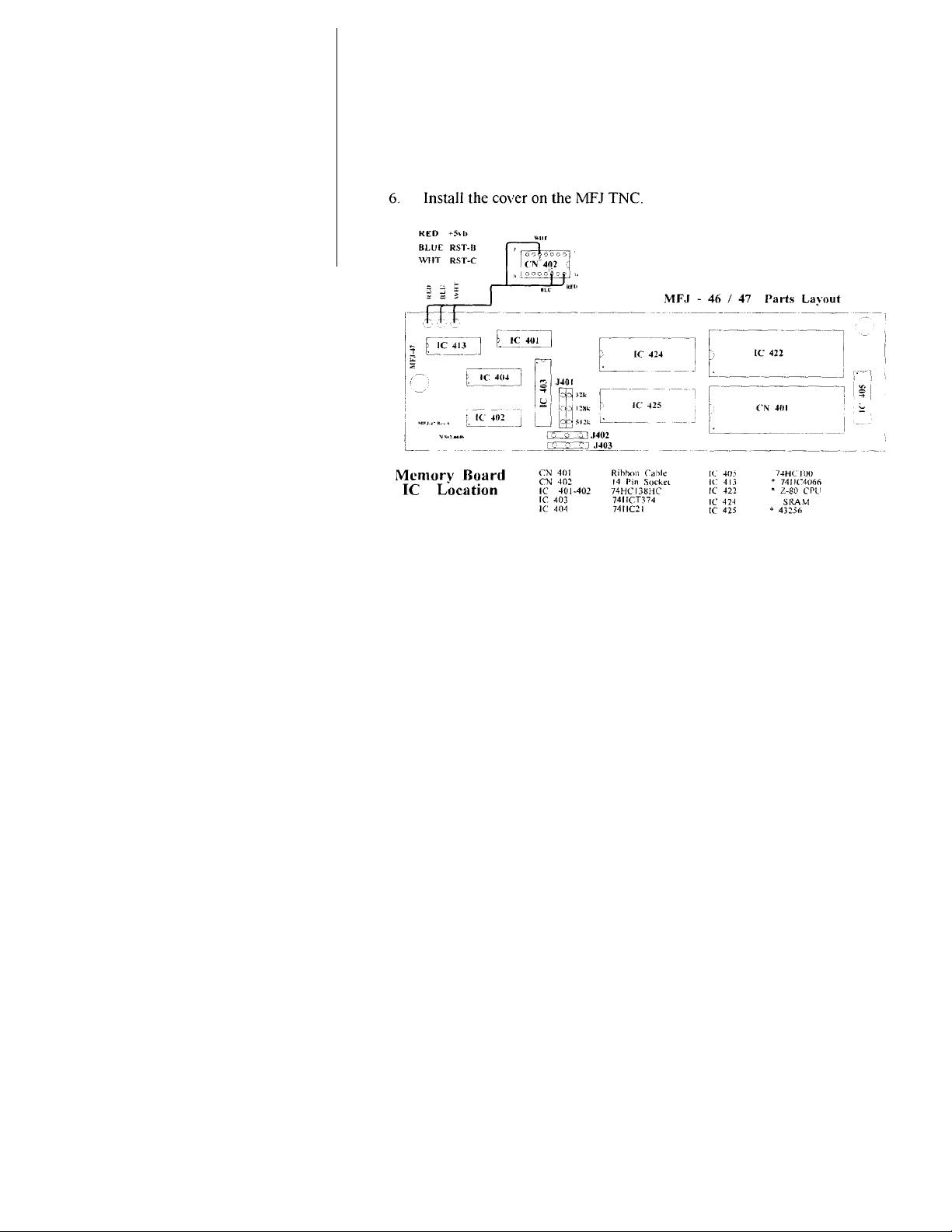
Install the RAM IC on the MFJ-47 expansion board as follows. Please refer
Figure 1 for IC location.
1. Remove all power and cables from the MFJ TNC.
2. Remove the top cover from the MFJ TNC. Remove the jumper from
3. Remove the U424 RAM IC on the memory board and reinstall the new RAM
IC at U424.
4. Re-locate the shorting jumper at J401 header as follows:
Item No. RAM Type J401/JMP19 Position
MFJ-45A 43256LP-10 (32K) The 2 inside most pins (32K)
MFJ-45B 431000LP-10 (128K) The 2 middle pins (128K)
MFJ-45C 8512LP-10 (512K) The 2 outside most pins (512K)
Table 1
NOTE:
J402. This enables the high address line when using a 512K
Page 2
MFJ-45 A/B/C RAM EXPANSION KIT
Inspect the newly installed RAM IC. Make sure that no IC pins are bent
or not properly inserted in the socket. Replace the jumper
5.
under the IC
removed in step #2, back at JMP5.
PROM MOTHERBOARD
Figure 1
7. Connect all power and cabling to the MFJ TNC.
8. Turn the computer ON, and load your terminal program.
9. Set the power switch on the MFJ TNC to ON. The MFJ TNC should sign- on
to the terminal. If not, then find out why the sign-on message was not
received.
10. Once the MFJ-TNC has signed-on to the terminal, then type the
command, RESET followed by a <CR>. This will enable the firmware to
automatically detect the RAM size change.
If the proper results were not obtained, then take the appropriate steps to
correct the problem. If the proper results were obtained, then congrats, you have
successfully completed the RAM Expansion Kit installation.
Page 3
MFJ-45 A/B/C RAM EXPANSION KIT
MFJ-1278 with MFJ -56 Installed
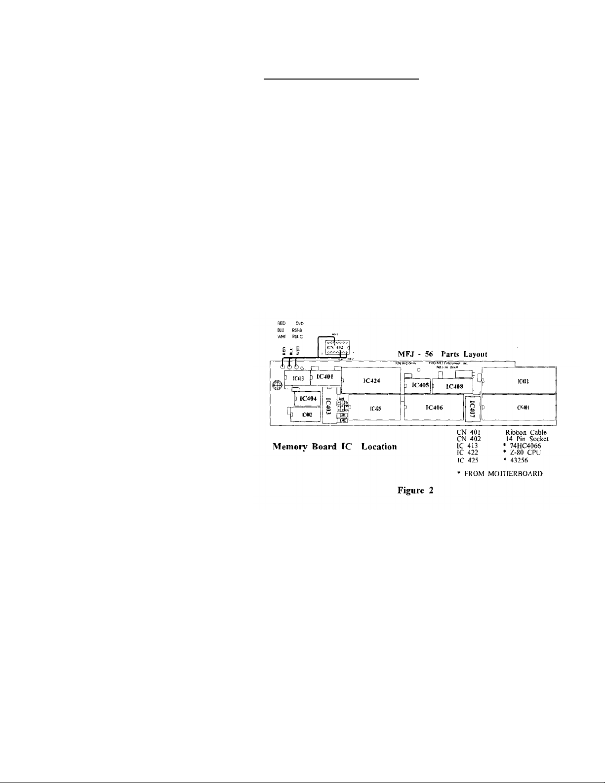
Install the RAM IC on the MFJ-56 expansion board as follows. Please refer to
the Figure 2 for IC location.
I. Remove all power and cables from the MFJ-1278.
2. Remove the top cover from the MFJ-1278. Remove the jumper from JMP5.
3. Remove the U424 RAM IC on the memory board and reinstall the new RAM IC at
U424.
4. Re-locate the shorting jumper at J401 header. Please refer to Table I on Page
1 for J401 positioning.
5. Inspect the newly installed RAM IC. Make sur e that no IC pins are bent under
the IC or not properly inserted in the socket.
6. Re-install the jumper removed in step #2, at JMP5.
NOTE: If installing a 512K RAM, then install a jumper on the rear two pins of
J402. This enables the high address line when using a 512K RAM.
Page 4

MFJ-45 A/B/C RAM EXPANSION KIT
7. Install the cover on the MFJ-1278.
8. Connect all power and cabling to the MFJ-1278.
9. Turn the computer ON, and load your terminal program.
10. Set the power switch on the MFJ-1278 to ON. The MFJ-1278 should signon to the terminal. If not. then find out why the sign-on message was not
received.
11. Once the MFJ-1278 has signed-on to the terminal, then type the
command, RESET followed by a <CR>. This will enable the firmware to
automatically detect the RAM size change.
If the proper results were not obtained, then take the appropriate steps to
correct the problem. If the proper results were obtained. then congrats. you have
successfully completed the RAM Expansion Kit installation.
MFJ-1278B/1274C/1270C
Install the RAM IC on the MFJ-1278B/1274C/1270C as follows. Please refer to the
Figure 3 for IC location.
1. Remove all power and cables from the TNC that the new RAM is to be
installed in.
2. Remove the top cover from the TNC. Remove the jumper from JMP5.
3. Remove the U24 RAM IC on the memory board and reinstall the new RAM
IC at U24.
4. Re-locate the shorting jumper at JMP19 header. Please refer to Table 1 on
Page 1 for JMP19 positioning.
5. Inspect the newly installed RAM IC. Make sure that no IC pins are bent under
the IC or not properly inserted in the socket.
6. Replace the jumper at removed in step #2, back at JMP5. 7.
Install the cover on the TNC.
Page 5

the
received.
RESET
automatically detect the
MFJ-45 A/B/C RAM EXPANSION KIT 8.
Connect all power and cabling to the TNC. 9. Turn the computer ON, and load
your terminal program.
10. Set the power switch on the TNC to ON. The TNC should sign-on to
terminal. If not. then find out why the sign-on message was not
11. Once the TNC has signed-on to the terminal, then type the command.
followed by a <CR>. This will enable the firm -are to
RAM size change.
Page 6

MFJ-45 A/B/C RAM EXPANSION KIT
If the proper results were not obtained, then take the appropriate steps to
correct the problem. If the proper results were obtained, then congrats. you have
successfully completed the RAM Expansion Kit installation.
If you had difficulties with any parts of the procedure. please feel free to
contact our friendly technical staff at 1-800-647-8324.
Page 7

MFJ-45 A/B/C RAM Expansion IC
The memory on the MFJ-46 (for MFJ-1278/1278T) or MFJ-47 (MFJ TNCs) mailbox memory
board can be expanded to 128K or 512K. If your current board has 32K memory you can
increase to 128K or 512K. If your current board has 128K you can increase to 512K.
Install the RAM IC on the MFJ -46 or MFJ-47 expansion board as follows (refer to the figure
below):
1. Remove power from the controller.
2. Remove the cover from the controller.
3. Remove U424 RAM IC on the memory board and reinstall the new RAM IC at U424. 4.
Relocate the shorting jumper at J401 header as follows:
Item No.
MFJ-45A 43256LP-10 (32K) The 2 inside most pins
MFJ-45B 431000LP-10 (128K) The 2 middle pins
MFJ-45C 8512LP-10 (512K) The 2 outside most pins
5. Inspect the RAM IC. Make sure that no IC pins are bent under the IC or not properly
inserted in the socket.
6. Install the cover on the controller.
RAM Type J401 Position
 Loading...