


MFJ-434B Instruction Manual Voice Keyer
INTRODUCTION
The MFJ-434B was designed by contesters and optimized to perform under the toughest
operating conditions. You don't need to be a contest superstar to appreciate what the MFJ-434B
can do. Even casual operators will discover the MFJ-434B is packed with user-friendly features
that make operating, both in and out of contests, more enjoyable and fun. Set it up, and you'll be
amazed how quickly it becomes part of your operating routine.
Before you begin, please read this manual thoroughly. It contains important information you'll
need to know before attempting to interface the MFJ-434B with your transceiver. We'll start
with a brief introduction to the special features that make your Voice Keyer an important
addition to any station, and an absolute necessity for any serious contest station:
Easy Selection: Large soft-touch switches select up to five pre-recorded messages.
Big Memory: Up to 75 seconds accumulated storage.
Dual Front Panel Microphone Connectors: Connect an 8 pin round or RJ-45 modular
connector equipped microphone.
Endless-Loop Timer: Convenient front panel controls adjust repeat-message interval of 0.5-50
seconds or 5-500 seconds. Timing cycle begins at the end of your message.
Built-in Mic Interface: Internal jumpers for connection to transceivers including Yaesu, Icom,
and Kenwood/Alinco radios.
Automatic Message Stop: Microphone PTT switch automatically halts outgoing messages.
Manual Message Stop: Prominent red STOP button halts outgoing messages.
Built-in Amplifier/Speaker: Monitors outgoing messages and previews stored messages.
Two Microphone Sources: Record from your station microphone for seamless audio
continuity, or use the built-in electret microphone.
External Microphone Power Select: Adjust internal jumpers to select the proper microphone
power level appropriate for your external microphone.
Off-Air Recording: Capture signals from your receiver's audio jack for review or replay.
RFI Proof Circuitry: Extensive suppression and line isolation virtually eliminates RF feedback,
hum, and distortion. Isolation transformer prevents mic circuit ground loops.
Dual-Level Gain: Spreads adjustment range for more precise mic gain settings.
Transparent Audio: Keyer electronics won't color your station's normal audio quality.
User-Friendly Panel: Intuitive controls for easy operation under pressure.
External Control: Fully buffered TTL or CMOS level control lines available at rear panel for
external PC or remote control interface. Works with popular logging programs like CT or NA.
Power Flexibility: Power from external filtered 9-15 Vdc external source, or power temporarily
with internal 9V battery.
Rugged Construction: Tough all aluminum cabinet and surface mount construction means DX-
pedition survivability, RF immunity, and years of reliable operation.
1
MFJ-434B Instruction Manual Voice Keyer
Once again, this manual contains important technical information and operating instructions
you'll need to know before using your keyer. Please read it thoroughly, and enjoy operating to
the fullest!
POWERING YOUR MFJ-434B
Important Note
: We recommend turning your radio on before powering up the voice keyer.
When some transceivers are turned off, the PTT line may be held low. This might cause the
keyer to boot up improperly and enter the self-test mode.
External Power: Use any well filtered power source capable of supplying 9-15 Vdc @100 mA
(minimum operating voltge is 8 Vdc under full load, sources exceeding 16 Vdc may permanently
damage this product). The keyer's external power jack accepts a standard 2.1mm coaxial power
plug (spares are available from Radio Shack). The power plug's center pin must be positive (+)
and ground-isolated. The outer shell is negative (-) and may be grounded or floated at the
supply. When connecting to a high current (more than one ampere) supply, we strongly
recommend fuse protecting both positive and negative supply leads with ½ ampere to 1 ampere
fast-blow fuses.
1-A
-
+
-
1-A
Power Supply+
WARNING: Never insert the power plug with power applied—an accidental short from
(+) to chassis ground may result. Also, never allow keyer supply voltage to exceed 16
Vdc. Connections to high current power sources must be fuse protected!
MFJ-1312B Power Supply: The MFJ-1312B wall adapter is also suitable for powering your
voice keyer. It comes with a 2.1mm power plug pre-installed, and is available directly from MFJ
or through your local MFJ dealer.
Internal Power: Use any fresh 9-volt battery for this application. Because current drain is
relatively high (15 mA on idle and 65 mA on transmit), battery life is typically quite short.
Continuous or prolonged operation on internal battery power is not recommended.
Important Note: MFJ does not recommend powering your unit with a 9-volt battery unless a
suitable external supply is unavailable. To install the internal 9-volt battery, remove the keyer's
cover and locate the battery snap inside. Note the plastic insulating sleeve covering the snap
terminals—this sleeve prevents the contacts from shorting to the case or other components. Slip
the sleeve down onto the wires so it won't become misplaced, and install the battery. Mount the
battery in its retainer on the back panel.
2
MFJ-434B Instruction Manual Voice Keyer
IMPORTANT WARNING: Remove the 9-volt battery when storing the keyer for extended
periods. Remember to reinstall the insulating sleeve on the snap clip.
CONNECTING AND OPERATING THE MFJ-434B
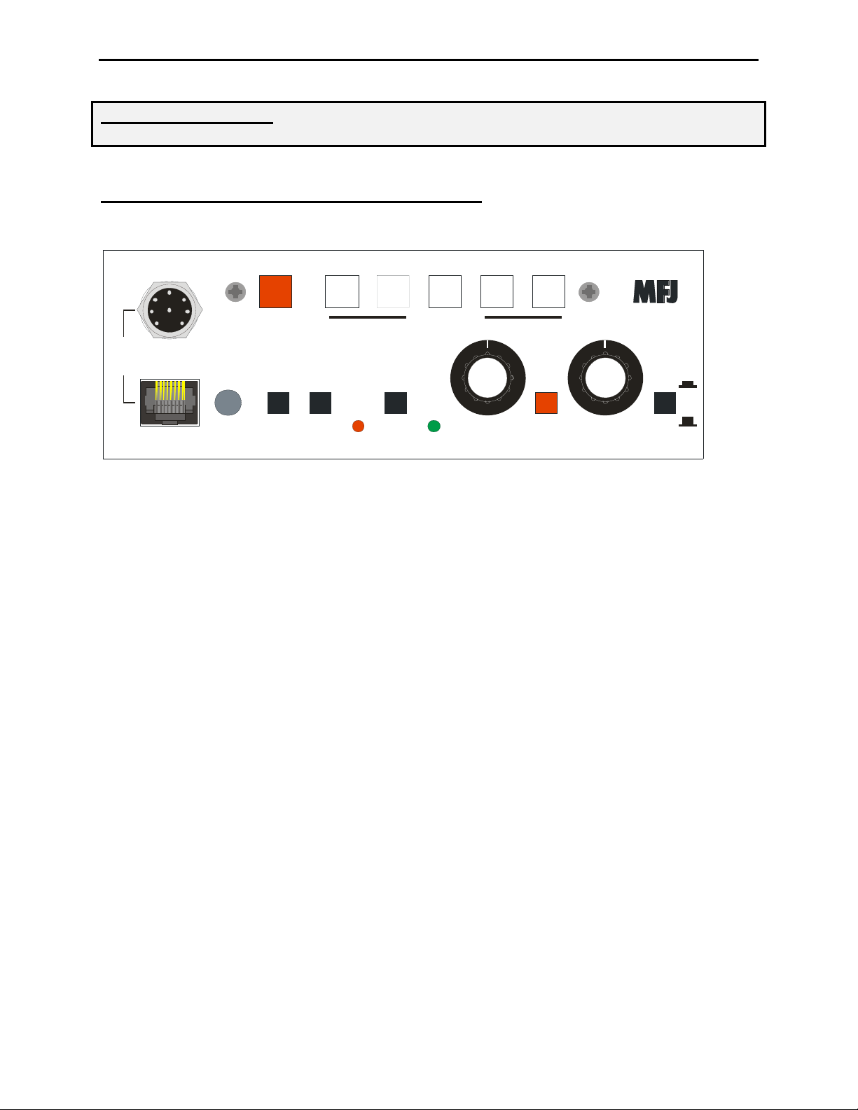
Front Panel:
STOP MSG 1 MSG 2 MSG 3 MSG 4 MSG 5
MESSAGES
EX TERNAL
MIC.
MFJ -434B
INTERNAL
MIC.
MFJ Voice Keyer
ONINT .
EXT.
XMIT
RECO RD
PLAY
PLAYREC
VOLUME
ON
OFFOFF
POWERMIC
REPEAT
DELAY
X10
X1
External Mic Jacks Plugs for 8 pin round or modular microphone connectors
Internal Mic Built-in electret microphone location
Mic Int./Ext. Selects internal (in), or external (out) microphone
Xmit On/Off Disables transmitter PTT line when reviewing messages
Record (LED) Illuminates in record mode, flashes during recording (red)
Record/Play Selects record mode (in), or play mode (out)
Play LED Illuminates when selector is in play mode (green)
Volume Controls volume of monitor speaker (and audio out jack)
Power On/Off Main power switch--on (in), off (out)
Repeat Delay Varies message-repeat interval (0.5-50 secs or 5-500 secs)
X1/X10 Multiplies message-repeat interval by x1 (out) or x10 (in)
Stop Halts message, cancels endless-loop function
Messages Selects message slots 1-5 and starts record or playback
3
MFJ-434B Instruction Manual Voice Keyer
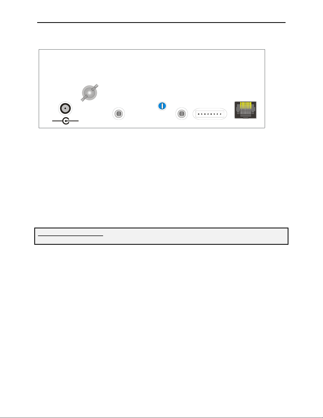
Rear Panel:
MFJ ENTERPRISES, INC.
STARKVILLE, MS USA
OUTP UT
POWER
12VDC
AUDIO
OUT
LEVEL
CONTROL
AUDIO
IN
REMOT E
STO P
MSG1
MSG2
MSG3
MSG4
MSG5
/XMIT
GND
TO
RADIO
MIC.
-
+
Power Requires 9-16 Vdc @ 100mA
Audio Out Monitor audio output, ~500 mW max
Output Level Control Adjusts microphone output level to radio
Audio In 600 Ohm input jack for recording external signals
Remote Port Remote access to messages and transmit busy lines
To Radio Mic Audio/PTT (RJ-45) output for radio's microphone input
Ground Ground terminal to station's ground buss
Microphone Connections
IMPORTANT WARNING: Never connect more than one microphone at once to the the
MFJ-434B. Damage may occur to the voice keyer or other connected equipment.
The MFJ-434B comes with a standard 8 pin round microphone connector and a RJ-45 modular
connector located on the front panel. These are the same types used by most transceiver
manufacturers. Since manufacturers wire these 8 pin connectors differently, the MFJ-434B
provides a convenient jumper interface to program its connectors for use with different
transceivers. This feature eliminates the need for re-wiring jacks or adding adapter cables. At
the MFJ factory, the interface is set for Yaesu transceivers with modular microphone connectors
(FT-817, FT-857, FT-897). If you operate one of these Yaesu transceivers, you may disregard
this section and use your keyer without resetting the interface jumpers. Jumper configurations
for other Yaesu radios are also located in the appendix. If you use a radio made by a different
manufacturer, or different connector refer to the section below.
An internal jumper (J6) selects external microphone voltage. Some microphones require
external voltage to operate. This jumper supplies 0, 1.5, 5, or 8 volts.
4
MFJ-434B Instruction Manual Voice Keyer
2
568
IMPORTANT WARNING: The MFJ-434B's internal jumpers are factory set for
compatibility with Yaesu transceivers (FT-817, FT-857, FT-897) using conventional
dynamic or crystal microphones. When using Icom or Kenwood/Alinco products,
internal jumpers must be reset for the correct manufacturer and microphone voltage.
Microphone Jumper Configuration (Icom, Kenwood, Yaesu)
1. Disconnect any 12VDC source from the MFJ-434B.
2. Next remove the screws from the sides and top of the voice keyer enclosure. Remove the
cover, being carful not to stress the monitor speaker wires.
3. Use Appendix A at the end of this manual to locate the jumper configuration specific to
your Icom, Kenwood, or Yaesu radio. If your radio is not included in the appendix use
the section below titled Microphone Jumper Configurations (Other Radios).
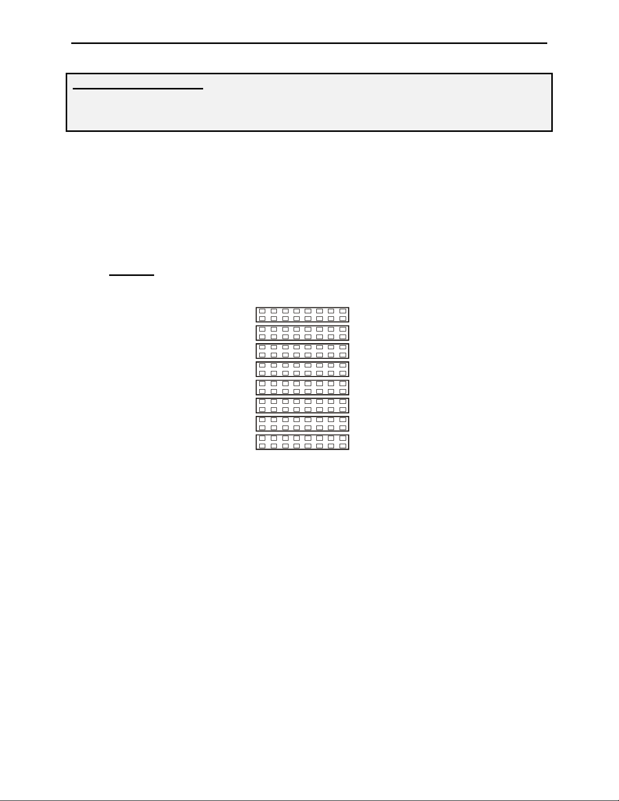
4. JMP2-9: On the left side of the circuit board, locate the set of headers JMP2-9. There
are 8 possible configurations on each row of jumpers 2-9. See the jumper diagram below.
3
JMP 9
1
4
7
Mic
JMP 8
JMP 7
JMP 6
JMP 5
JMP 4
JMP 3
JMP 2
Mic Gnd
PTT
PTT Gnd
Direct
Mic
Mic Gnd
PTT
5. Remove the jumpers on JMP2-9 ONLY.
6. Replace the jumpers on JMP2-9 using the diagram specific to your radio located in the
Appendix of this manual. If your radio is not listed use the following section for
determining the jumper settings for other radios.
7. Replace the cover and screws when you have completed the configuration.
Microphone Jumper Configuration (Other Radios)
1. If your radio is not included in the appendix, the MFJ-434B can be configured by
obtaining a copy of the wiring diagram specific to your radio microphone.
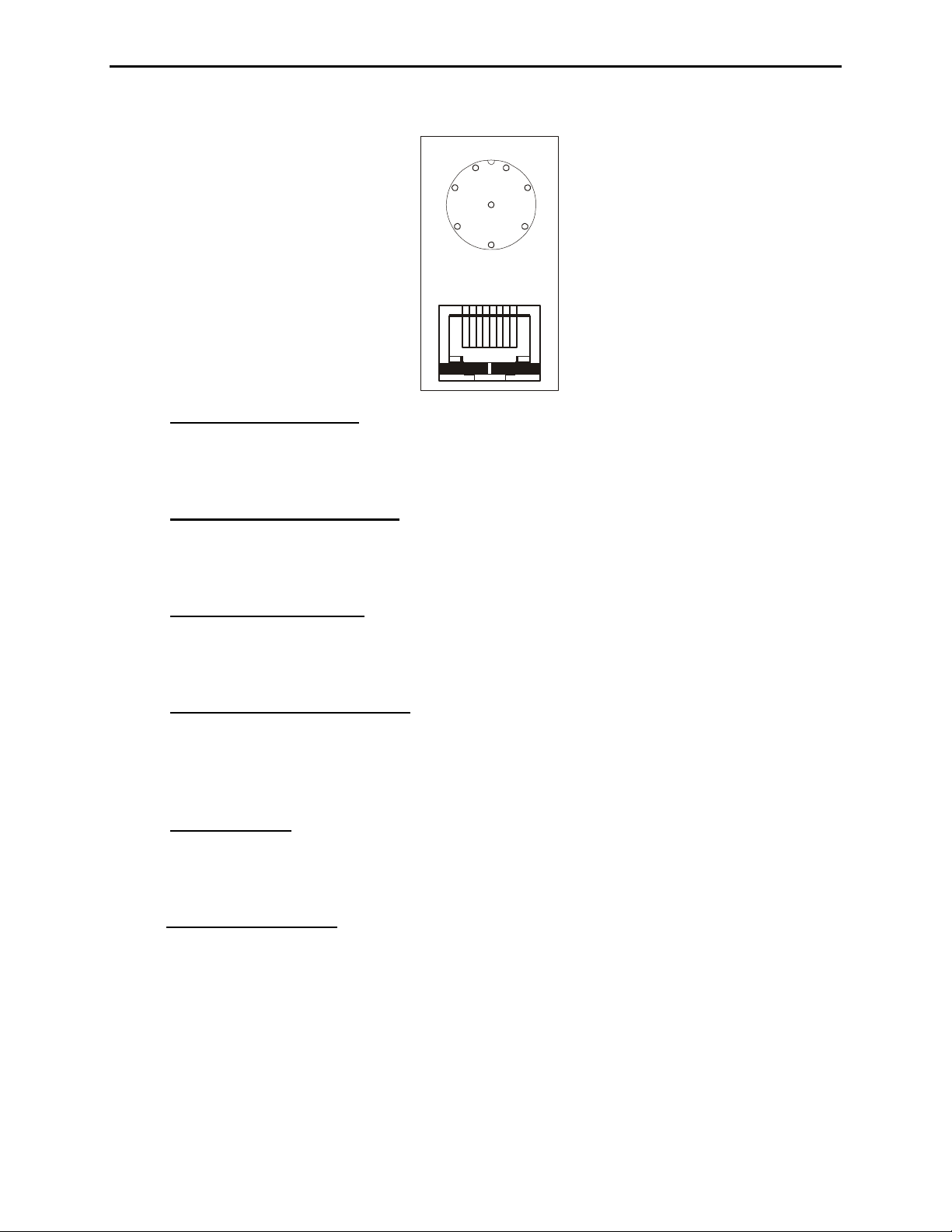
2. Use the microphone wiring diagram to determine which microphone pins are used for
PTT, PTT Gnd, Mic, Mic Gnd. The front panel view of the microphone connectors
below can be used to determine how the pins will need to be configured.
5
MFJ-434B Instruction Manual Voice Keyer
Front Panel View
7
1
2
6
8
3
5
4
87654321
3. JMP4 and JMP9 (Mic): Place jmp 4 and jmp 9 on the corresponding pin number
required by your microphone. This pin number can be determined from the front panel
view above. For example if your radio has Mic input on pin 1 a jumper will be placed on
jmp9 pin 1 and jmp4 pin 1.
4. JMP3 and JMP8 (Mic Gnd): Place jmp 3 and jmp 8 on the pin number required by
your microphone. This pin number can be determined from the front panel view above.
For example if your radio has Mic Gnd on pin 7 a jumper will be placed on jmp3 pin 7
and jmp8 pin 7.
5. JMP2 and JMP7 (PTT): Place jmp 2 and jmp 7 on the pin number required by your
microphone. This pin number can be determined from the front panel view above. For
example if your radio has Mic Gnd on pin 5 a jumper will be placed on jmp2 pin 5 and
jmp7 pin 5.
6. JMP5 and JMP6 (PTT GND): This is often refered to as Ground in some radio
manuals. Place jmp 5 and jmp 6 on the pin number required by your microphone
configuration. This pin number can be determined from the front panel view above. For
example if your radio has PTT Grnd on pin 6 a jumper will be placed on jmp5 pin 6 and
jmp6 pin 6.
7. JMP5 (Direct):
Place jumpers on jmp5 (direct) on remaining lines not configured above.
These pins will control up/dn, +VDC, squelch, AF, and other functions commonly found
on transceivers. By placing a jumper on jmp5 the MFJ-434B circuit is by-passed on the
corresponding pins.
8. JMP6 (Mic Voltage):
There are four jumper pins near the front of the circuit board(to
the rear of the green LED), labeled JMP6 with 8V, 5V, 1.5V, and 0V markings. This
jumper is normally set at 0V, which is compatible with Yaesu and other standard
dynamic and crystal microphones that do not require external voltage. If you are using a
microphone that does require external voltage, or if your microphone does not record to
the voice keyer but works normally when connected to the voice keyer, consult the
specifications for your microphone. Place the jumpers in the setting that most closely
matches the voltage specified by your microphone manufacturer.
6
MFJ-434B Instruction Manual Voice Keyer
IMPORTANT WARNING: Do not inadvertently change the jumper on HD1. This jumper is
set on pins 7-8 and should not be moved.
Other Internal Adjustments
Please note two other important internal settings while the cover is off and the pc board visible:
1. Dual Gain Control, R29: This trimpot, located next to the audio isolation transformer,
sets the overall adjustment range of the Output Level Control located on the rear panel.
If you find the back panel gain control must be adjusted to an extreme setting (high or
low) to provide the correct levels to your radio, you may reset R29 to bring the Output
Level Control back into its center range.
2. PTT Automatic Override, JMP1: This jumper plug enables the Automatic Override
feature that stops outgoing messages whenever the PTT switch is pressed. When the plug
is removed, the automatic override function is disabled.
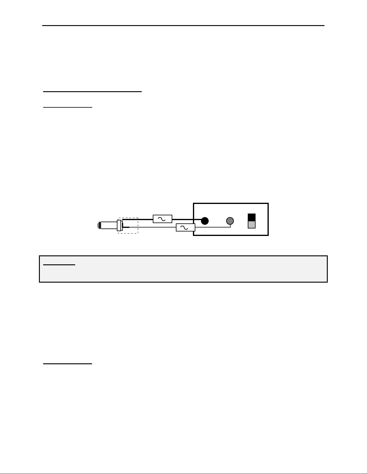
Audio Lines
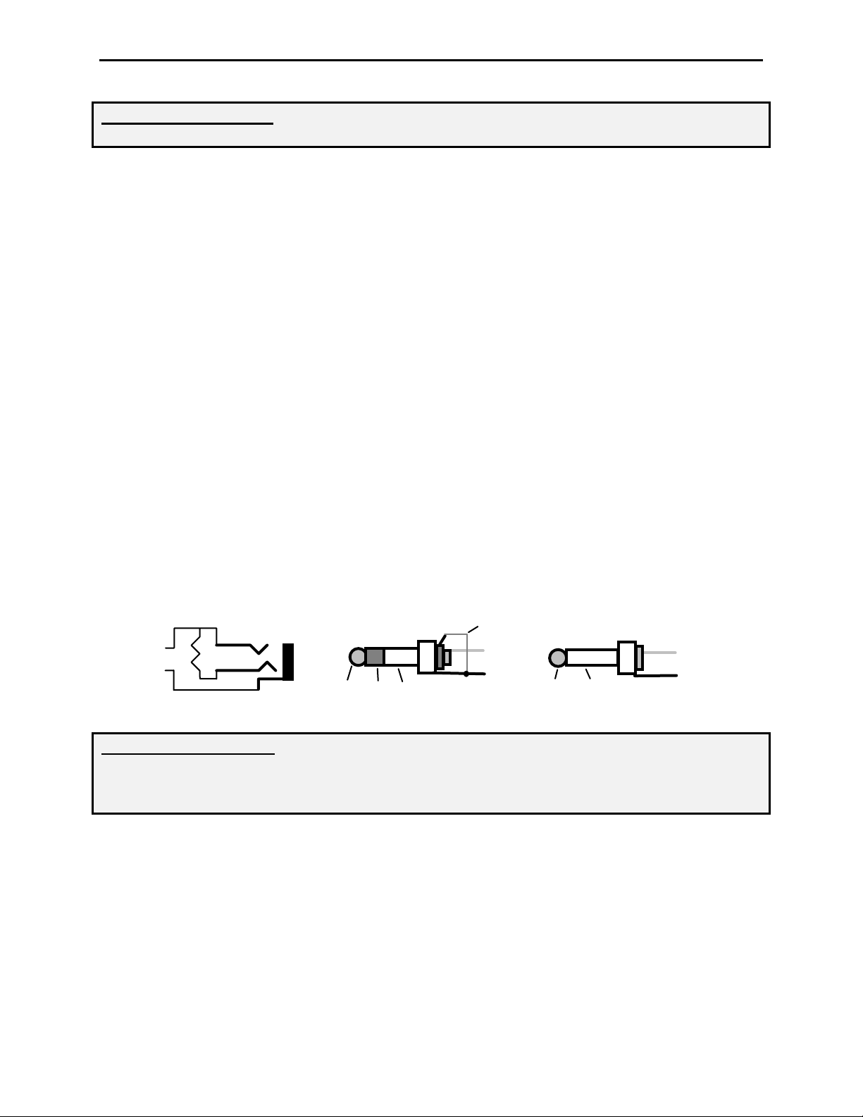
Audio In: This 3.5mm jack accepts audio signals from a receiver or other low impedance
monaural source for recording. Maximum input level is 0 dBm at 600 Ohms (2 Vpp), and the
minimum usable level is –23 dBm into 600 Ohms (0.15 Vpp). Inserting a plug automatically
disconnects the keyer's internal electret mic. Both jack terminals float with respect to ground to
permit connecting balanced or unbalanced sources. If you experience station microphone hum
with an external audio source plugged in, install a 600 Ohm 1:1 audio isolation transformer in
the external audio line (RadioShack RS273-1374). All audio lines, balanced or unbalanced,
should be grounded at one end only.
Omit for Hi-Z source
Audio
680
Stereo Plug
Tip
Ring
Audio
Sleeve
Mono Plug
Tip
Sleeve
Audio
IMPORTANT WARNING: Never exceed 3 Vdc or 3 Vpp input on the “Audio In” jack. If
recorded audio is distorted, either reduce the external audio level control or add external
attenuation to reduce level. When using stereo plugs, connect the ring terminal to the
sleeve for 600-Ohm lines, or leave open for hi-Z audio sources.
Audio Out: This 3.5mm jack provides a low impedance monaural output signal from the
keyer's monitor amplifier, disconnecting the internal speaker when a plug is inserted. Output is
unbalanced, and the monitor amplifier delivers a maximum undistorted signal level of
approximately 4Vpp into 4 ohms (or about 500 mW RMS). The jack's tip lead is "hot" and the
sleeve is connected to both signal and chassis ground. When using stereo plugs, do not wire to
the ring terminal (see input jack diagram above). Note that stereo headphones will not function
properly when plugged into this jack.
Remote Port Connections
7
 Loading...