

Page 1
MFJ-4117 Bias-Tee with DC Switch
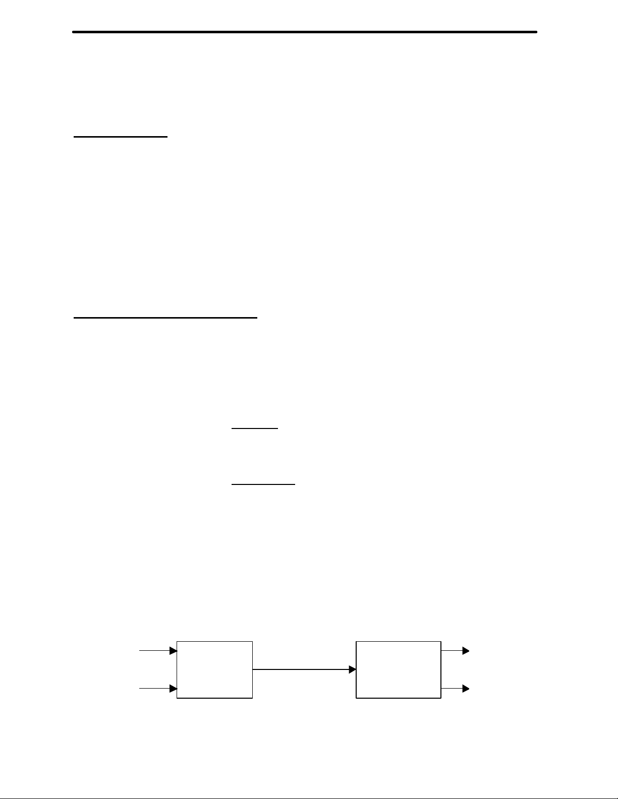
DC
RF
DC / RF
DC
RF
1-60 MHz
INTRODUCTION
The MFJ-4117 Bias-Tee is ideal for running coax to distant devices allowing them to be placed
anywhere regardless of power availability. Several MFJ products have a built in Bias-Tee, so the
DC / RF coaxial cable can be directly connected to them as well.
The MFJ-4117 Bias Tee operates on frequencies ranging from 1-60 MHz. The Bias-Tee is used
to inject DC voltage onto coaxial lines. The DC voltage is separated from the RF signal by
another MFJ-4117 on the terminating end (See Figure 1). Any standard 2.1 mm 1-50 VDC, 1
Amp maximum adapter will work. The MFJ-4117 is equipped with a DC switch to turn the
remote equipment on and off.
INSTALLATION INSTRUCTIONS
1. Connect the transmitter to the “RF IN/OUT” coaxial connector on Bias-Tee 1 using a
50-ohm coaxial cable. (See Figure 1) This is the RF signal input connector.
2. Connect a DC adapter to the “DC IN\OUT” jack. This is your DC voltage input
connector.
3. If the device you are using does have a built in Bias-Tee, connect the device to the
“RF/DC OUT/IN” coaxial connector on Bias-Tee 1 using 50-ohm coaxial cable. The
device will recover the RF and DC signals.
4. If the device you are using does not have a built in Bias-Tee, connect the “RF/DC
OUT/IN” coaxial connector from Bias-Tee 1 to the “RF/DC OUT/IN” coaxial
connector on Bias-Tee 2 using a 50-ohm coaxial cable. This is your RF/DC out of BiasTee 1 into Bias-Tee 2 to be recovered.
5. Connect the device to the “RF IN/OUT” coaxial connector of Bias-Tee 2 using a 50ohm coaxial cable. This is your recovered RF signal output connector.
6. Connect the device to the “DC IN\OUT” of Bias-Tee 2 using a DC adapter. This is your
recovered DC voltage output connector.
Switch
in
in
Bias-Tee
1
Figure 1: MFJ-4117 Bias-Tee Operation Diagram
Bias-Tee
2
out
out
 Loading...