

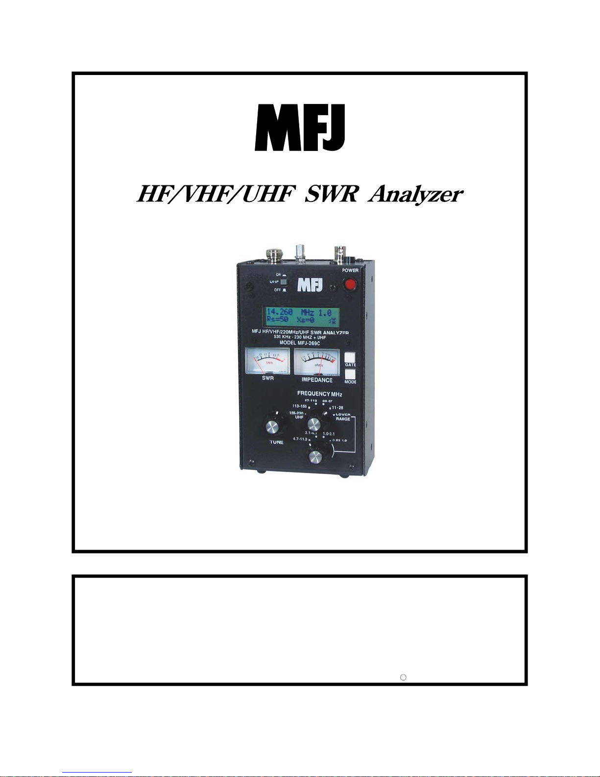
Model MFJ-269C
INSTRUCTION MANUAL
CAUTION: Read All Instructions Before Operating Equipment
MFJ ENTERPRISES, INC.
Tel: 662-323-5869 Fax: 662-323-6551
VERSION 1A
300 Industrial Park Road
Starkville, MS 39759 USA
COPYRIGHT 2014 MFJ ENTERPRISES, INC.
C

MFJ-269C Instruction Manual LF/HF/VHF/UHF SWR Analyzer
TABLE OF CONTENTS
1.0 INTRODUCTION 2
1.1 TYPICAL USE 2
1.2 FREQUENCY RANGE 3
1.3 ACCURACY NOTES 3
2.0 POWER SOURCES 4
2.1 EXTERNAL POWER SUPPLY 4
2.2 INTERNAL BATTERIES 5
2.3 RECHARGEABLE BATTERIES 5
2.4 USING CONVENTIONAL “AA” DRY CELL BATTERIES 6
2.5 “VOLTAGE LOW” DISPLAY WARNING 6
2.6 SLEEP MODE “POWER SAVING” 6
3.0 MAIN MENU AND DISPLAY 7
3.1 GENERAL CONNECTIONS 7
3.2 POWER-UP DISPLAY 7
3.3 MAIN MEASUREMENT MODES (LF/HF/VHF, 0.53-230 MHZ) 8
3.4 FREQUENCY CONTROL 9
4.0 MAIN (OR OPENING) MODE 10
4.1 GENERAL CONNECTIONS 10
4.2 ANTENNA SWR AND IMPEDANCE 10
4.3 COAX LOSS (FUNCTION-2) 12
4.4 CAPACITANCE (FUNCTION-3) 13
4.5 INDUCTANCE (FUNCTION-4) 14
4.6 FREQUENCY COUNTER (FUNCTION-5) 15
5.0 ADVANCED OPERATION 15
5.1 FORWARD 15
5.2 ACCESSING ADVANCED MODES 16
5.3 GENERAL CONNECTIONS 17
5.4 ADVANCED -1 MODES 17
5.5 ADVANCED- 2 MODES 23
5.6 ADVANCED 3 (LF/HF/VHF ONLY) 29
ii

MFJ-269C Instruction Manual LF/HF/VHF/UHF SWR Analyzer
6.0
ADJUSTING SIMPLE ANTENNAS 30
6.1 DIPOLES 30
6.2 VERTICALS 31
6.3 TUNING A SIMPLE ANTENNA 31
7.0 TESTING AND TUNING STUBS AND TRANSMISSION LINES 31
7.1 TESTING STUBS 31
7.2 VELOCITY FACTOR OF TRANSMISSION LINES 32
7.3 IMPEDANCE OF TRANSMISSION LINES OR BEVERAGE ANTENNAS 33
7.4 ADJUSTING TUNERS 34
7.5 ADJUSTING AMPLIFIER MATCHING NETWORKS 35
7.6 TESTING RF TRANSFORMERS 35
7.7 TESTING BALUNS 35
7.8 TESTING RF CHOKES 36
8.0 TECHNICAL ASSISTANCE 37
iii

MFJ-269C Instruction Manual LF/HF/VHF/UHF SWR Analyzer
ATTENTION: READ SECTION 2.0 BEFORE ATTEMPTING TO USE
THIS PRODUCT. INCORRECT POWER SUPPLY VOLTAGES OR
EXCESSIVE EXTERNAL VOLTAGES APPLIED TO THE ANTENNA
CONNECTOR WILL DAMAGE THIS UNIT.
1.0 INTRODUCTION
The MFJ-269C is a compact battery powered RF impedance analyzer. It combines five basic circuits; a
variable oscillator, frequency counter, frequency multiplier, 50-ohm RF bridge, twelve-bit A-D converter,
and a microcontroller. Together, these circuits perform a wide variety of useful antenna and RF
impedance measurements including coaxial cable loss and electrical distance to an open or short.
Although mainly designed for analyzing 50-ohm antenna and transmission line systems, the MFJ-269C
also measures RF impedance from a few ohms to several hundred ohms. An easy-to-access usercontrolled Zo setting in the Advanced function menus facilitates changing SWR and other SWR
functions (i.e. return loss, reflection coefficient, match efficiency, etc) to any normalized impedance value
between 5 and 600 ohms. The MFJ-269C also functions as a non-precision signal source and frequency
counter. Operating frequency extends from 0.53 to 230 MHz in nine overlapping bands with extended
SWR measurement from 415 to 470 MHz. (LF coverage may be adjusted to cover 0.470 kHz).
1.1 Typical Use
The MFJ-269C may be used to adjust, test, or measure the following:
Antennas: ...................................SWR, impedance, reactance, resistance, resonant frequency, and
bandwidth
Antenna tuners:..........................SWR, bandwidth, frequency
Amplifiers:.................................Input and output matching networks, chokes, suppressors, traps, and
components
Coaxial transmission lines: ........SWR, length, velocity factor, approximate Q and loss, resonant
frequency, and impedance
Filters:........................................SWR, attenuation, and frequency range
Matching or tuning stubs: ..........SWR, approximate Q, resonant frequency, bandwidth, impedance
Traps: .........................................Resonant frequency and approximate Q
Tuned Circuits:...........................Resonant frequency and approximate Q
Small capacitors:........................Value and self-resonant frequency
RF chokes and inductors:...........Self-resonant frequency, series resonance, and value
Transmitters and oscillators:......Frequency
The MFJ-269C measures and directly displays the following:
Electrical length (feet or deg)
Feedline Loss (dB)
Capacitance (pF) Reactance or X (ohms) Signal Frequency (MHz)
Impedance or Z magnitude (ohms) Resistance or R (ohms) SWR (Zo programmable)
Impedance phase angle(degrees) Resonance (MHz)
Inductance (μH)
Return loss (dB)
2

MFJ-269C Instruction Manual LF/HF/VHF/UHF SWR Analyzer
The MFJ-269C is also useful as a non-precision signal source. It provides a relatively pure (harmonics
better than -25 dBc) signal of approximately 3 Vpp (~20 mW) into a 50 ohm load. The internal source
impedance is 50 ohms. Although not "stabilized", it provides adequate stability for non-critical
applications such as alignment of broad-bandwidth filters and circuits.
: For a more complete description of features and test methods, consult the table of contents to find
Note
the manual sections describing the particular measurement you wish to make.
1.2 Frequency Range
The unit's dual-range Frequency switches select the following oscillator bands with a small overlap:
0.53-1.0 MHz 4.7-11.0 MHz 67-113 MHz
1.0-2.1 MHz 11-28 MHz 113-155 MHz/UHF LO*
2.1-4.7 MHz 28-67 MHz 155-230 MHz/UHF HI*
*A UHF pushbutton switch located above the LCD display activates 415-470 MHz SWR coverage. See
section 3.4 for VFO operating specifics.
1.3 Accuracy Notes
If measurement errors occur, they will likely be caused by one of the following conditions:
1. Signal ingress from external sources, usually from a strong AM broadcast station.
2. Diode detector and A/D converter error.
3. Stray impedance errors contributed by connectors, cables, and adapters.
Broad-band Voltage Detectors and External Interference: Laboratory grade network analyzers use
expensive high-selectivity gain-stabilized receivers to avoid off-frequency interference and ensure
measurement accuracy. Building these sophisticated detectors into the MFJ-269C (or any small handheld
unit) would drive the price far beyond the reach of most hobbyists. As an alternative, we use broadband
detectors that provide accurate measurements at a much lower cost. The only drawback is that broadband
detectors can be sensitive to powerful out-of-band signals. Most of the time, out-of-band interference isn't
an issue, but occasionally a particularly powerful signal may be picked up by the antenna under test and
routed into the analyzer bridge circuit where it conflicts with the internally generated VFO signal. When
strong "signal ingress" such as this occurs, it may result in inaccurate readings.
The solution for out-of-band interference isn't simple. Increasing the analyzer's generator power would
help, but doing so causes the unit to draw significantly more power at the expense of reduced battery
operating time. Higher power may also cause on-air interference when testing antenna systems that
radiate efficiently or exhibit directivity gain. Using common low-pass or band-pass filters similar to those
used in transceivers also wouldn't work because they behave like transmission lines of varying impedance
on different frequencies. Using them would only introduce gross measurement inaccuracies.
MFJ-731: Fortunately, most analyzer interference problems occur on the lower frequencies, with near-by
high power AM broadcast signals being the worst offender. When testing physically large antenna arrays
such as 160-meter verticals, these powerful outside signals may couple very efficiently into the analyzer's
bridge circuit. Other strong local signals may "get in" as well. To correct the problem, we offer the MFJ731 tunable filter, an accessory especially designed to attenuate off-frequency signals. The MFJ-731
3
MFJ-269C Instruction Manual LF/HF/VHF/UHF SWR Analyzer
permits accurate impedance measurements between 1.8 and 30 MHz with virtually no impact on
measurement accuracy.
Detector Errors: At low voltages, detector diodes become non-linear. To address this issue, the MFJ269C uses special microwave zero-bias Schottky detectors with matched compensating diodes. Each unit
is individually compensated to provide the best detector linearity possible. Small errors may also occur
during A/D conversion due to practical limitations on bit resolution.
Connection lengths: Connection lengths both inside and outside the analyzer bridge can upset readings,
especially at higher frequencies and when impedance is very high or very low. The MFJ-269C minimizes
internal problems by using surface mount low capacitance microwave components with nearly zero lead
length. It's important to remember that any external leads you add, even short leads, will modify the
impedance of the load at radio frequencies. To obtain highest accuracy, always use the shortest test cables
possible with the fewest connectors and adapters in the line.
: Some handheld analyzers display erroneous readings falling outside the reliable measurement
Note
range, presenting that data numerically -- as if it were "factual". The MFJ-269C is designed to avoid such
errors by displaying an on-screen warning (Z > 1500) anytime data falls outside the unit's accurate
measurement range.
2.0 POWER SOURCES
This section describes power supply and battery selection.
READ THIS SECTION BEFORE CONNECTING THIS DEVICE TO ANY POWER SOURCE.
IMPROPER CONNECTIONS OR INCORRECT VOLTAGES MAY CAUSE DAMAGE TO THIS
PRODUCT!
2.1 External Power Supply
The MFJ-1312D satisfies all external voltage and current power source requirements and we highly
recommend using it with your MFJ-269C. External power requirements are as follows:
1. When the unit is ON, supply voltage must be over 11 volts but not exceeding 16 volts.
2. When in Sleep Mode or OFF (supply lightly loaded), voltage must not exceed 18 volts.
3. The supply must be well filtered against hum and noise.
4. The MFJ-269C case (chassis ground) must be connected directly to the supply's negative terminal.
5. The supply must not have a grounded positive lead (- center pin).
6. The "ideal" supply voltage is 13.8 volts dc.
7. When rechargeable batteries are used, 13.8 volts is required for charger operation.
8. Current demand is 150 mA (max) on HF and VHF, 250 mA (max) on UHF.
WARNING: READ SECTION 2.2 THROUGH 2.4 (BATTERY INSTALLATION INSTRUCTIONS)
BEFORE INSTALLING BATTERIES.
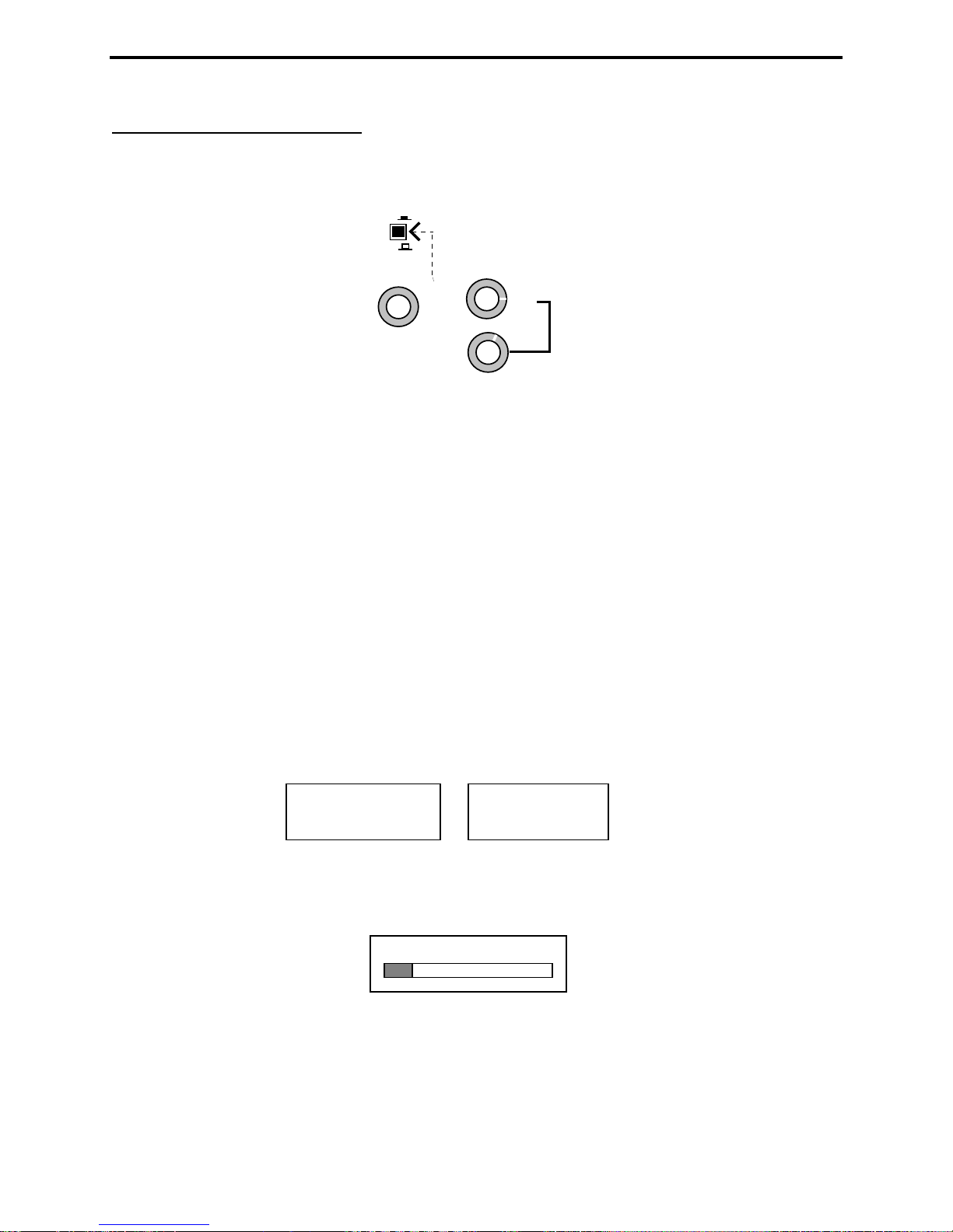
The MFJ-269C has a recessed 2.1 mm power receptacle near the RF connectors. This receptacle is
labeled POWER 13.8 VDC. The outside conductor is negative, the center is positive. Inserting a
4
MFJ-269C Instruction Manual LF/HF/VHF/UHF SWR Analyzer
power plug in the POWER 13.8 VDC receptacle disables internal batteries as the analyzer's power
source. However, the internal batteries will still be trickle charged when the power supply plug is
inserted into the unit. Power plugs must be wired as shown below:
+
2.1 mm
+
-
WARNING: REVERSE POLARITY OR EXCESSIVE VOLTAGE CAN DAMAGE OR DESTROY THE
MFJ-269C. NEVER APPLY MORE THAN 18 VOLTS, NEVER USE AC OR POSITIVE
GROUND SUPPLIES! NEVER ADD OR REMOVE BATTERIES WITH AN EXTERNAL
POWER SUPPLY CONNECTED TO THIS UNIT, OR WITH THE POWER SWITCH ON.
2.2 Internal Batteries
When installing internal batteries, first check the position of a small black-plastic internal jumper plug
that controls charger operation. The jumper is located inside the unit at the top of the printed circuit
board near the area of the OFF-ON switch and power connector. To access it, remove all eight screws on
the sides of the case and remove the back cover. The black plastic jumper fits over two of three adjacent
pins (see detailed instructions below). The plug must be properly positioned for the type of cell you plan
to use (AA rechargeable or AA non-rechargeable).
2.3 Rechargeable Batteries
Important Note: When using rechargeable batteries, your external power source must deliver at least 14
volts. If supply voltage is too low, the charger can't function and batteries will eventually discharge. If
batteries are depleted, charge with the analyzer power switch turned off -- it may take ten hours or more
to fully restore depleted cells.
Important Warning: Never change batteries with the power switch "On" or with an external supply
plugged in -- permanent damage may result. Always remove batteries when shipping the analyzer or
storing it for an extended period (more than a month).
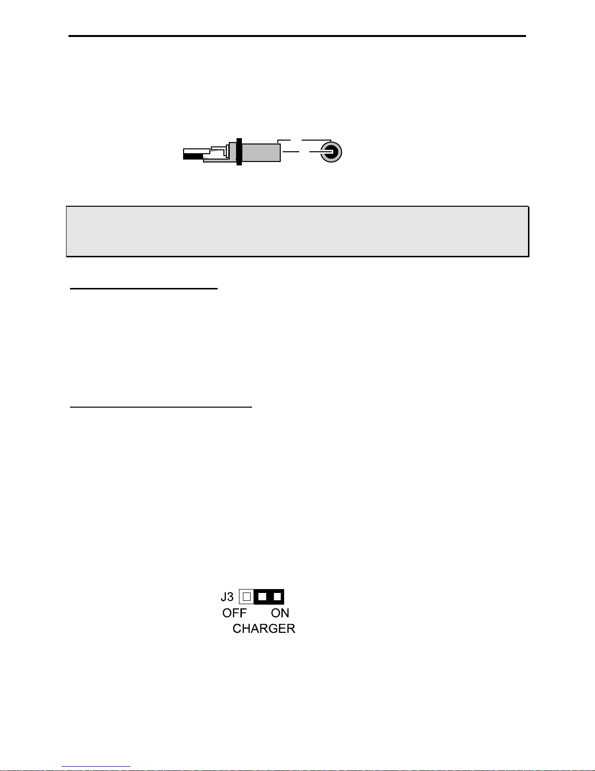
When using rechargeable batteries, the internal black plastic jumper must be set to the proper position.
Remove the analyzer cover and locate the jumper on the pc board (near the power jack). Confirm that it is
set correctly. If not, reposition as shown below:
Again, when the Charger Jumper is ON and a 13.8 to 18 volt source is applied, the charger will be
functional. Typical charging current is 10-20 mA.
5
MFJ-269C Instruction Manual LF/HF/VHF/UHF SWR Analyzer
2.4 Using Conventional “AA” Dry Cell Batteries
When using non-reachable batteries, install only high quality alkaline cells in matched sets (same
manufacturer and date code). Conventional zinc-based cells have a shorter shelf and service life, and they
are also more prone to leakage. Also, to prevent leakage, remove weak alkaline batteries immediately.
WARNING: WHEN USING NON-RECHARGEABLE BATTERIES, THE CHARGING SYSTEM MUST
BE DEFEATED! IF YOU FAIL TO FOLLOW THIS WARNING, THE BATTERIES WILL
LIKELY LEAK AND RUIN THE ANALYZER!
When using non-rechargeable batteries, set the internal jumper as shown below:
Never attempt to charge alkaline (or any other non-rechargeable cells) using the MFJ-269C's internal
charger circuit!
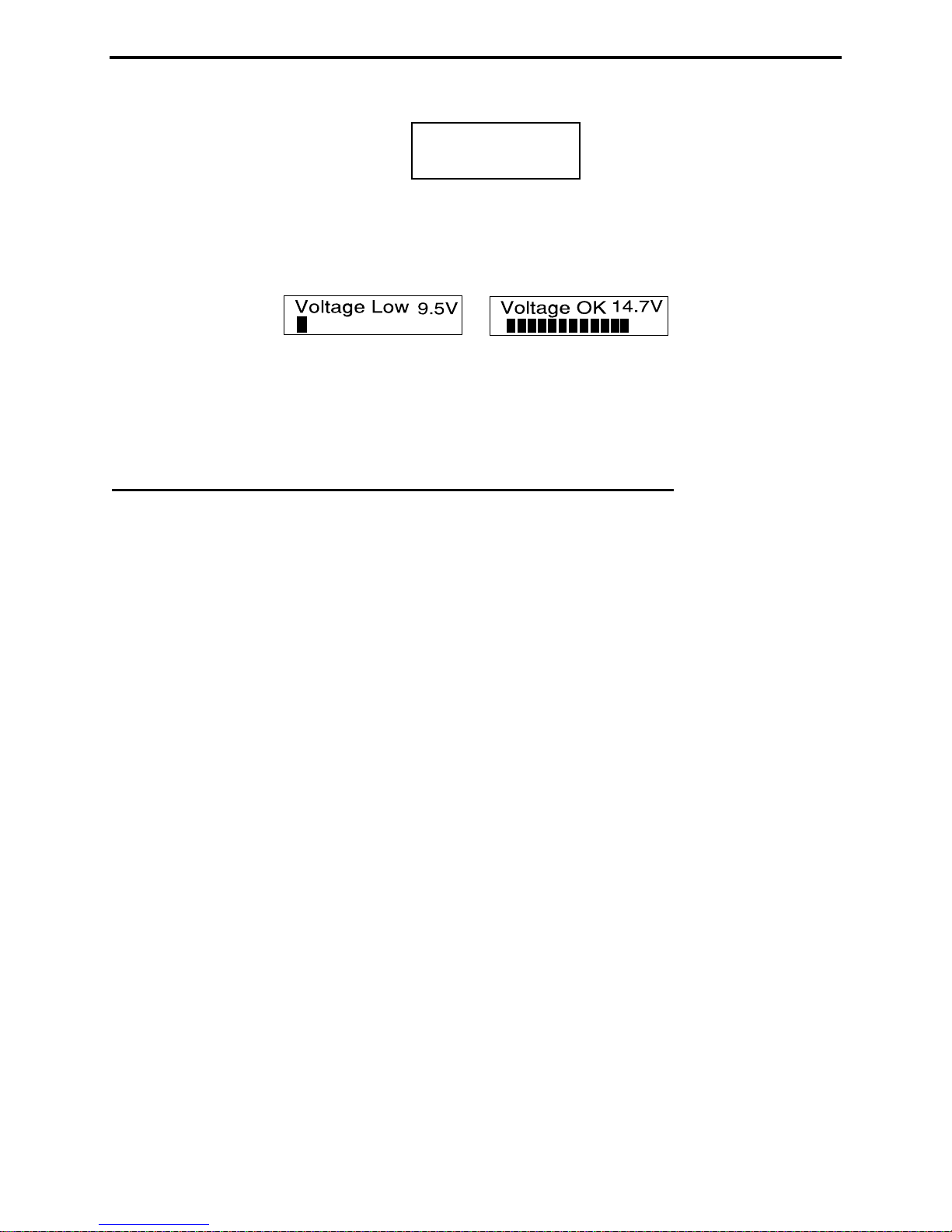
2.5 “Voltage Low” display warning
When the analyzer's supply or battery voltage drops below 11 volts, a blinking Voltage Low warning
will be displayed. Pressing Mode during a low-voltage warning will disable the on-screen alert and allow
you to continue operating. However, measurements may not be reliable when operating the analyzer with
insufficient supply voltage!
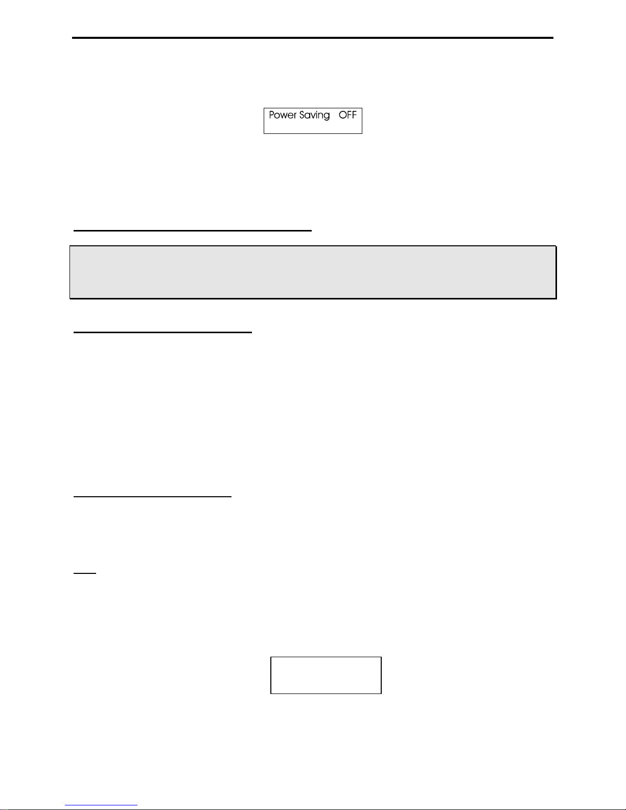
2.6 Sleep Mode “Power Saving”
Typical current drain for the MFJ-269C is around 150 mA for HF operation (250 mA for UHF). Battery
operating time is (by default) extended significantly through the use of Sleep Mode. Sleep mode reduces
current drain to less than 15 mA when it is engaged during periods of non-activity. Power-saving is a
default setting for the MFJ-269C unless you defeat it when you turn on the analyzer (instructions below).
Normally, the analyzer's processor looks for manual activation of the Mode switch or for any change in
Frequency greater than 50 kHz. If neither event occurs during any given three-minute interval, Sleep
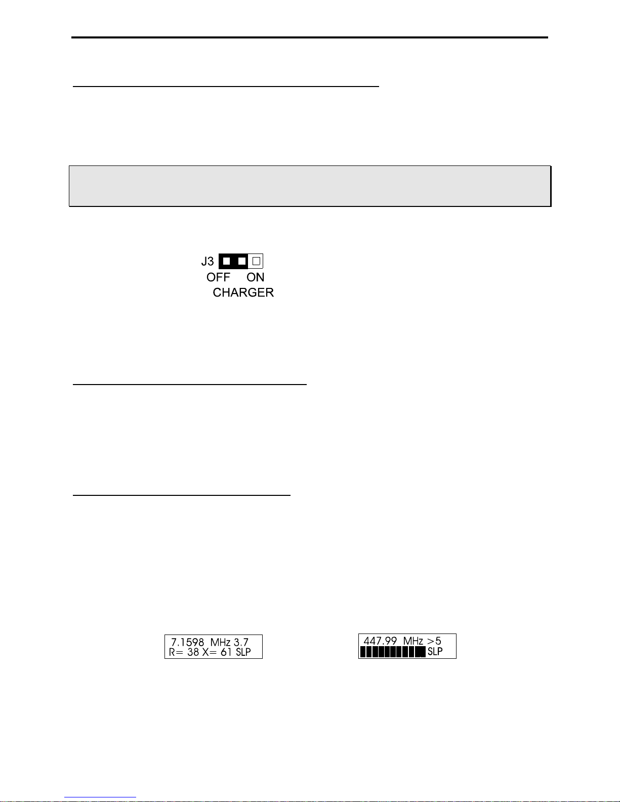
mode automatically kicks in and places the analyzer in standby. A blinking SLP message in the display
screen lower-right corner indicates power-saving mode (see below):
To pull the unit out of SLP, momentarily press either the Mode or Gate button to resume operation.
To disable Sleep, first turn the unit Off and then press and hold the Mode button when reapplying power.
Continue holding Mode until after the copyright message appears on the LCD screen, then release. If the
6
MFJ-269C Instruction Manual LF/HF/VHF/UHF SWR Analyzer
“Power Saving” mode has been is successfully disabled, the message shown below will appear as soon as
Mode is released.
Sleep Mode is a default function and will reset automatically each time the analyzer is turned OFF. To
restore Sleep, simply turn the analyzer Off and then On again.
3.0 MAIN MENU AND DISPLAY
WARNING: NEVER APPLY RF OR ANY OTHER EXTERNAL VOLTAGE TO THE ANTENNA PORT.
THE MFJ-269C USES ZERO BIAS DETECTOR DIODES THAT MAY BE DAMAGED BY
EXTERNAL VOLTAGES. ALSO, READ SECTION 2.0 BEFORE APPLYING POWER.
INCORRECT SUPPLY VOLTAGE OR REVERSED POLARITY CAN CAUSE DAMAGE.
3.1 General Connections
The N-female Antenna connector on top of the unit is the primary RF-measurement connection. It is
used for all functions except frequency counter measurements.
The Power connector (2.1 mm) is described in section 2.0. Please read the power-source section carefully
before attempting to operate the analyzer! Improper voltage application, the wrong battery charger
setting, or reversed polarity could permanently damage your unit.
The BNC Frequency Counter Input is for frequency counter measurements only. See section 4.5 for the
counter's operating instructions.
3.2 Power-up Display
Important Note: Before powering up the analyzer, check the status of the UHF switch located above the
LCD window on the left. This switch must be in the "up" or in the Off position unless UHF operation is
intended.
Note: The following is a description of the basic opening (or default) menu used by the MFJ-269C. Your
analyzer also has an advanced user section (5.0).
When applying Power, a sequence of message screens appear on the LCD display. The first screen lists
the software version (Ver): Be sure to have this number handy when referring technical questions about
your analyzer to MFJ Customer Service:
The second message shows the software copyright date:
MFJ-269C
Ver 14.14
7
MFJ-269C Instruction Manual LF/HF/VHF/UHF SWR Analyzer
MFJ Enterprises
(c) 2014
The third message is a voltage check. It displays the operating voltage, indicating battery condition or the
voltage of your external power supply.
The fourth and final screen is the first "working display" (Complex Impedance). The two analog panel
meters also activate when the working display comes up.
3.3 Main Measurement Modes (LF/HF/VHF, 0.53-230 MHz)
Momentarily pressing (or tapping) the Mode button after the first working display appears allows you to
scroll through all five basic measurement modes provided by the MFJ-269C. The opening mode is
Impedance R & X (resistance and reactance). As each new mode comes up, its title screen appears for
about two seconds, and then the companion data screen appears. Each of the five Basic Modes are listed
below:
1. Impedance R&X: This is the analyzer's "default mode", and it is the function most commonly used.
The top line of the data screen displays Frequency in MHz and SWR, while the bottom line shows
complex impedance where Rs equals the load's series resistive component and Xs shows the load's series
reactive component. In this function, the analog SWR and Impedance Meters (Z) are also activeated.
2. Coax Loss: Pressing Mode once brings up the Coax Loss -- followed by the data screen. The top line
shows Frequency in MHz and the bottom line displays Coax Loss in dB.
3. Capacitance in pF: The third mode displays Frequency in MHZ on the top line, followed by Xc
(capacitive reactance) on the bottom line. The analog meter also shows reactance X.
4. Inductance in μH: The fourth mode, Frequency appears on top and X
bottom. Meter shows reactance (X).
5. Freq. Counter: The fifth function turns off the analyzer's internal oscillator and routes the input of the
counter to the BNC connector labeled Frequency Counter Input. In this mode, the top line of the LCD
display shows the measured Frequency in MHz and the counter's Gate Time in seconds.
Important Note: Section-4 of this manual provides detailed instructions for using each of the five basic
operating modes described above. To ensure accurate measurement and avoid the possibility of
inadvertent damage, please read through this section carefully before operating the analyzer!
L (inductive reactance) on the
8
MFJ-269C Instruction Manual LF/HF/VHF/UHF SWR Analyzer
3.4 Frequency Control
The MFJ-269C tunable RF-oscillator covers an exceptionally wide frequency span, using two rotary band
switches for LF/HF/VHF coverage (.53-230 MHz) -- plus an additional pushbutton switch to activate
UHF coverage (415-470 MHz) .
UHF
ON
OFF
TUNE
FREQUENCY MHz
67-113 28-67
113-155
UHF LO
155-230
UHF HI
2.1-4.7 1.0-2.1
4.7-11
11-28
Lower
Range
0.53-1.0
1. LF, HF and VHF Operation: The Lower Range rotary switch selects four LF and HF bands (0.53-
11.0 MHz). The Upper Range switch selects 5 HF and VHF bands for 11-230 MHz coverage. Note that
the Upper Range switch must be set fully clockwise to the Lower Range position for the lower-range
band selector to function. The variable Tune control (VFO capacitor) provides a small overlap at each
band edge to ensure gap-free tuning across the spectrum.
*Note that LF coverage may be lowered to 0.47-0.94 MHz (or lower) for 600-Meters and select maritime
services. To modify, (1.) adjust Tune fully counter-clockwise, (2.) remove the back cover (3.) Remove
battery pack by removing Philips head screws and, (4.) using a 2-mm hex tuning wand, readjust inductor
L12 while watching the frequency display.
2. UHF Operation: UHF coverage is broken into two bands. To measure UHF SWR (415-490 MHz),
first press in the UHF switch located just above the LCD display. Then, for 415-470 MHz coverage, set
the upper Frequency MHz switch to the 113-155 MHz band (UHF LO). For 470-490 MHz coverage,
set the upper Frequency MHz switch to 155-230 MHz. (UHF HI).
It is normal for the VFO's Tune range to exceed the analyzer's usable UHF measurement range. If the
VFO frequency is out of range in UHF Mode, one of the error messages shown below will instruct you to
increase or decrease frequency to bring it back in range:
INCREASE
FREQUENCY
DECREASE
FREQUENCY
Adjust Tune clockwise to increase frequency and counterclockwise to decrease frequency. When in
range, the operating Frequency will appear on the top line of the LCD display -- along with the SWR
reading. The bottom display line becomes an analog SWR bar-graph (see below).
Remember to set the top Frequency MHz selector fully counterclockwise (155-230) when setting up for
445.75 MHz 1.3
UHF HI (470-490MHz) or set to the second to last switch position (113-155) when setting up for UHF
LO (415-470 MHz) measurements. The analyzer converts the analyzer's VHF oscillator up to the UHF
band for those measurements.
9

MFJ-269C Instruction Manual LF/HF/VHF/UHF SWR Analyzer
4.0 MAIN (OR OPENING) MODE
IMPORTANT WARNING: Never apply RF or DC voltages to the Antenna port of this unit. It uses zero
bias detector diodes that are easily damaged by any external voltages over a few volts. Also, confirm
the power supply voltage and polarity are correct, as described in Section-2.0.
A basic understanding of antenna theory and transmission line behavior will prove helpful for making the
best use of the data provided by your MFJ-259C. The ARRL Handbook and ARRL Antenna Book
provide concise peer-reviewed explanations that should suffice for most applications. When it comes to
the finer points of antenna design, there is (unfortunately) a fair amount of misinformation circulating on
the web and over the airwaves. When it comes to RF networks and antenna systems, there's no black
magic. Stick with the fundamentals as presented by credible professional sources.
4.1 General Connections
When conducting SWR and Impedance measurements, follow these practical guidelines:
1. Connectors: If connector transitions (RF adapters) are needed, use only high-quality parts and check
them for wear, oxidation, dirt, and tight pin contact before proceeding.
2. Lead Length: Make all connection electrically secure and keep all leads as short as possible. This
precaution is especially important when measuring electrical components that are not part of a 50-ohm
coaxial system.
3. Coaxial Cable: Always use good quality 50-ohm cable and connectors when making SWR
measurements. Contaminated, mismatched, or damaged cable will introduce significant error.
4. Calibration Plane: When making Complex Impedance measurements, (R+X) or (Z), remember that
any length of transmission line you install between the load and the analyzer will displace the load
from the analyzer's calibration plane.
For simple handheld analyzers like the MFJ-269C, the calibration plane is always located at the
analyzer's RF connector. This is the point where Zo=50 Ohms and Phase shift = 0 degrees. It is the only
test point where the analyzer will be calibrated for complex impedance measurements. Displacing the
load away from the analyzer's calibration plane through random lengths of coax should have little or no
impact on SWR readings, but will introduce significant error through phase shift and transformer action
to invalidate virtually any complex impedance measurement you might make.
When measuring Complex Impedance, always install the MFJ-269C as close (electrically) as possible
to the DUT (device under test)!
4.2 Antenna SWR and Impedance
Use the N-Female Antenna connector located on top of the MFJ-269C for all RF measurements (except
those using the Frequency Counter mode). Follow the procedure outlined below for measuring SWR:
1. If your antenna doesn't have a dc-grounded feed system, momentarily short the cable's center conductor
to the shield immediately before connecting up to the analyzer. This simple procedure will discharge any
static buildup on the antenna and prevent damage to the analyzer's sensitive detector diodes.
10
 Loading...