

Page 1
2. - MFJ 269 TEST & CALIBRATION PROCEDURE
,
g
g
2.1. Introduction
The box can be tested completely after assembling with the battery holder
initially unassembled. An initial PCB pre calibration procedure is assumed.
The operations indicated in the procedure can be followed under normal conditions
(getting oscillations impedance and SWR meter working), otherwise some troubleshooting
may be required.
A multimeter
2.2 Procedure
- Check appearance of box, if any defects inform to the assembly persons.
- Set the unit in test mode by pressing the mode and the gate time switches buttons
in the order previously indicated.
a spectrum analyzer, a scope (optional), a calibrated frequency counter, a
2.2.1 Checkin
2.2.2 Band Overlappin
- Set the TEST mode (read 1.I if it is necessary to remind the procedure).
- Set the 4th TEST mode step where the internal oscillator frequency will be displayed and
The unit at the HF/VHF mode has to cover continuously from 170 to 1.8 MHz. Check
that the band overlapping realized in the PCB precalibration is still correct.
the RF amplifier bias and the AGC
"
"
- Using the variable capacitor, slowly cover the band looking for a consistent
frequency reading in the counter module. Notify, if erratic behavior is observed.
- Repeat the previous operation to cover all the
bands. Readjust the setting where necessary.
Page 2

2.2.3 Voltage calibration
.
p
It may me necessary to repeat the previous interactively to get the desired settings.
Adjust the trimmer R67 to read 50 ohms on the 7 needle meter. .,
-
- Set the unit around 430 Hz and verif an SWR reading close to one and a zero
ohm im
edance needle meter reading. 145 MHz
2.24 Inductance and capacitance modes
Page 3
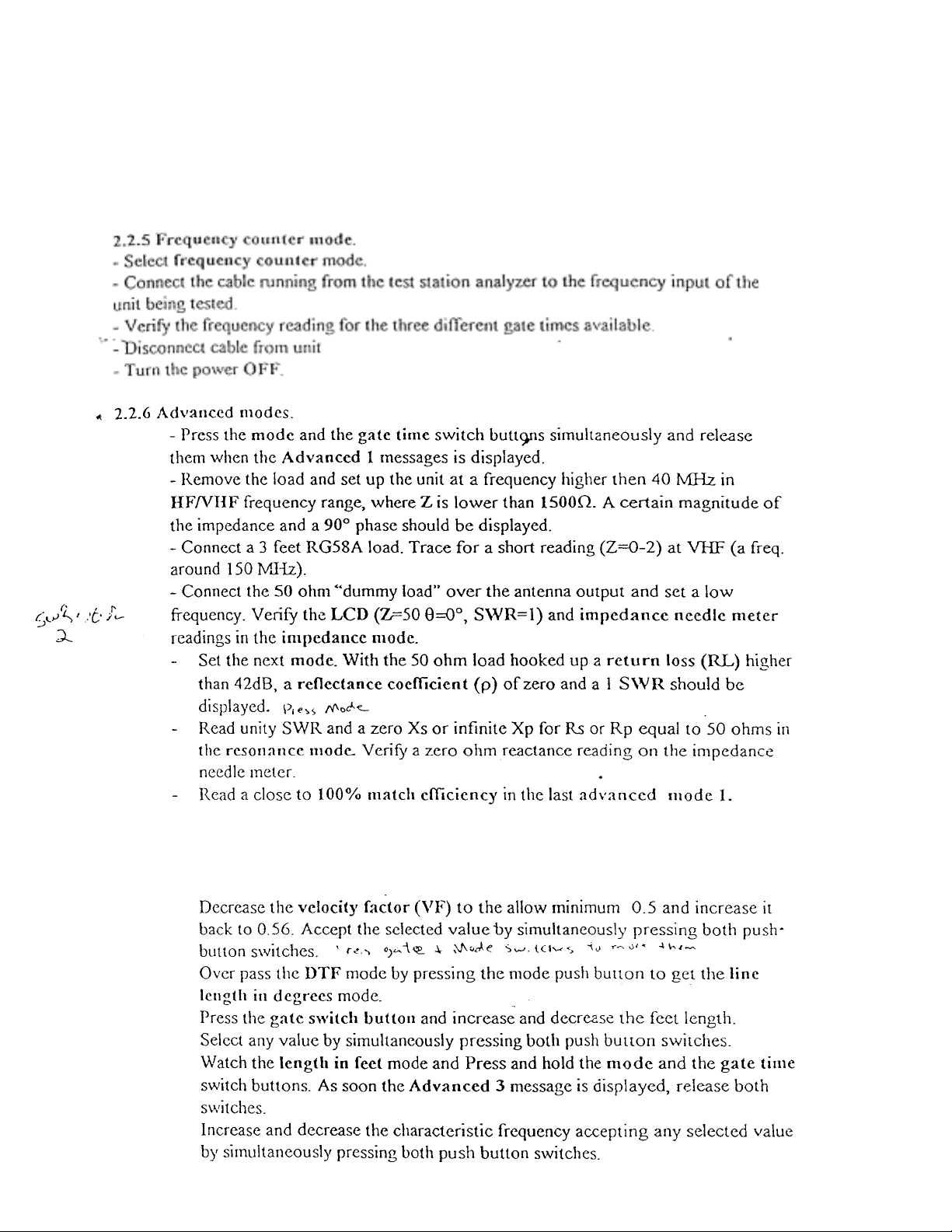
- Set the unit to a frequency higher than 60 MHz and verify a close to
p
F reading.
4
-Press and hold the mode and the gate ti me switch b uttons. As soon the
Advanced 2 message is di splayed, release b oth switches.
Page 4

- Remove the load, set to the minimum frequency and verify the Z>1500
LCD reading. Watch the SWR label blinking.
2.2.1.6 Battery l ead s te st.
- Install the battery charger jumper in the OFF position.
- Assembly the battery holder.
- Apply 12 Vdc to the ba tter y lead s conside ring the pol arity and tu rn ON the powe r.
Page 5

3.1.) Test point definition
These test point are labeled on the PCB as follow (numbers and test points could be
Page 6

Page 7

 Loading...