

INSTRUCTION MANUAL
CAUTION: Read All Instructions Before Operating Equipment
MFJ ENTERPRISES, INC.
300 Industrial Park Road
Starkville, MS 39759 USA
Tel: 662-323-5869 Fax: 662-323-6551
COP YRIGH T 2012 MF J EN TE RPR IS ES, IN C.
C
Model MFJ-266B
VERSION 1D

MFJ-266B HF/VHF/UHF Antenna Analyzer Instruction Manual
2012 MFJ Enterprises, Inc. Version 1D ii
DISCLAIMER
Information in this manual is designed for user purposes only and is not
intended to supersede information contained in customer regulations,
technical manuals/documents, positional handbooks, or other official
publications. The copy of this manual provided to the customer will not
be updated to reflect current data.
Customers using this manual should report errors or omissions,
recommendations for improvements, or other comments to MFJ
Enterprises, 300 Industrial Park Road, Starkville, MS 39759. Phone:
(662) 323-5869; FAX: (662) 323-6551. Business hours: M-F 8-4:30
CST.

MFJ-266B HF/VHF/UHF Antenna Analyzer Instruction Manual
2012 MFJ Enterprises, Inc. Version 1D iii
Contents
1.0 Introduction........................................................................................................... 1
2.0 Power Sources........................................................................................................ 2
2.1 Internal Batteries............................................................................................... 2
2.2 External Power Supply...................................................................................... 3
3.0 Operating Mode ..................................................................................................... 3
3.1 Display Backlight.............................................................................................. 3
3.2 Main Menu Screen............................................................................................ 4
3.3 Frequency Counter Mode (D -> FC)................................................................. 4
3.4 Antenna Analyzer Mode (U -> ANT)............................................................... 5
3.5 RF Signal Source .............................................................................................. 5
3.6 L/C Measurement Mode ................................................................................... 5
4.0 Frequency Selection.............................................................................................. 6
4.1 Variable Tuning ................................................................................................ 6
4.2 Range Selection ................................................................................................ 6
4.3 HF-Band Selection............................................................................................ 6
5.0 Accuracy Limits..................................................................................................... 7
5.1 SWR Measurements and Local Interference..................................................... 7
5.2 Checking for Local Interference........................................................................ 7
5.3 Detector Linearity and Accuracy....................................................................... 7
5.4 Calibration-Plane Error..................................................................................... 8
5.5 Sign Ambiguity (± j)......................................................................................... 8
6.0 Antenna Measurements.......................................................................................... 9
6.1 Antenna Connectors.......................................................................................... 9
6.2 SWR.................................................................................................................. 9
6.3 Measuring SWR................................................................................................ 9
6.4 SWR, Bandwidth, and Resonance................................................................... 10
6.5 Antenna Tuning .............................................................................................. 10
6.6 Antenna matching........................................................................................... 11
6.7 Matching Antennas Through A Tuner (ATU)................................................. 11
6.8 Antenna Impedance Readings......................................................................... 11
6.9 Unpredictable SWR ........................................................................................ 12
7.0 Advanced Functions............................................................................................. 12
7.1 Frequency Measurement................................................................................. 12
7.2 Field Strength Measurement ........................................................................... 13
7.3 Stimulus Generator as a Signal Source............................................................ 13
7.4 Measuring Unknown Capacitance................................................................... 13
7.5 Measuring Unknown Inductance..................................................................... 14
7.6 Tuning a ¼-Wave or ½-Wave Coaxial Stub.................................................... 14
7.7 Determining Velocity Factor........................................................................... 15
7.8 Testing RF Transformers ................................................................................ 15
7.9 Checking HF Baluns....................................................................................... 16
7.10 Checking Coax Cable.................................................................................... 16
8.0 Quick Guide to Analyzer Controls and Functions................................................ 17
Technical Assistance.................................................................................................. 19
12 MONTH LIMITED WARRANTY....................................................................... 20

MFJ-266B HF/VHF/UHF Antenna Analyzer Instruction Manual
2012 MFJ Enterprises, Inc. Version 1D 1
1.0 INTRODUCTION
Important: Read Section-2 before attempting to use your analyzer -applying incorrect operating voltages could result in permanent damage!
Also, never apply a DC voltage to the antenna connector.
General Description: The MFJ-266B is a self-contained handheld RF
analyzer that performs the following diagnostic functions:
SWR (1:1 to 9.9:1)
Complex Impedance (Z = R + jX)
Impedance Magnitude (Z = ΩΩΩΩ)
Capacitance (pF)
Inductance (uH)
Relative Field Strength (mV)
Frequency (MHz)
The MFJ-266B also generates a 2-dBm RF signal that may be used to
check receivers, networks, amplifiers, and antenna patterns. Operating
range is:
HF: 1.5 - 71 MHz in six HF bands
VHF: 85-185 MHz continuous coverage
UHF: 300-490 MHz continuous coverage
A 10:1 vernier drive provides smooth tuning. Measurements are
displayed on an easy-to-read LCD screen with optional backlighting.
Power is supplied by internal AA cells or by a regulated 12-VDC
external power source (not included). Weighing just over 1.3 pounds, the
MFJ-266B package fits comfortably in one hand for convenient bench
work or on-the-fly testing in the field. Operation is simple, but you will
need to read the manual to learn all of the unit's features and functions.
The more you know the more valuable it will become as a diagnostic
tool.
MFJ-266B HF/VHF/UHF Antenna Analyzer Instruction Manual
2012 MFJ Enterprises, Inc. Version 1D 2
2.0 POWER SOURCES
The MFJ-266B may be powered with internal AA batteries or with an
external DC supply. To avoid needless damage and ensure top
performance, please follow the guidelines below when choosing a
voltage source.
2.1 Internal Batteries
To access the jumpers and battery compartments, remove all four screws
securing the analyzer's back cover and carefully open the case. To
operate the MFJ-266B on batteries put the EXT PWR-BAT jumper on
the PC board in the BAT position and install the batteries.
Battery power requires 4 (four) AA-size 1.5-volt alkaline cells. Batteries
are installed in a fully encased 4-cell plastic trays mounted inside the
analyzer enclosure. Slide the battery box covers sideways to unlatch, and
then lift vertically to expose the cells.
Slide and
Lift
When replacing old batteries, be sure to follow the manufacturer's
environmental guidelines for safe disposal. For longest battery life,
always replace with a matched set of factory-fresh cells. The MFJ-266B
will not charge batteries in the AA cell pack. Do not use rechargeable
AA cells in the pack.
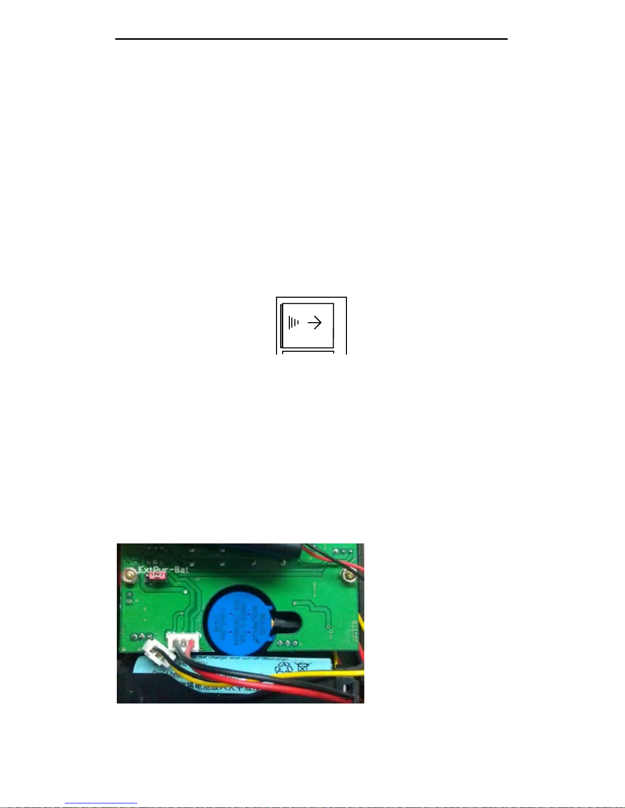
The MFJ-266B can also hold an optional rechargeable 18650 battery.
This battery is inserted into a holder that is at the bottom of the case.
Disassemble the case as listed above and insert the battery into the holder
making sure the polarity is correct. This battery is recharged from the
external supply through a special charging circuit built into the MFJ266B. Charging time is about 10 hours using the MFJ-1312B. The
18650 battery will only
charge when the MFJ266B is off. For
charging the position of
the EXT PWR-BAT
jumper does not matter.
It will charge in either
position.
To switch between the
AA cell pack and the
rechargeable 18650
unplug the 3 pin header
from the AA cell pack and plug in the 3 pin header from the 18650 pack.
MFJ-266B HF/VHF/UHF Antenna Analyzer Instruction Manual
2012 MFJ Enterprises, Inc. Version 1D 3
2.2 External Power Supply
To operate the MFJ-266B on an external power supply open up the unit
and move the EXT PWR-BAT jumper from to EXT PWR. The MFJ266B will not run on external power and batteries at the same time.
Powering the MFJ-266B externally requires a well-filtered 12V DC
supply such as the MFJ-1312D capable of delivering 12 to 15 VDC
under varying load conditions. Current drain ranges from 30 mA to 180
mA, depending on operating mode, frequency range, and whether or not
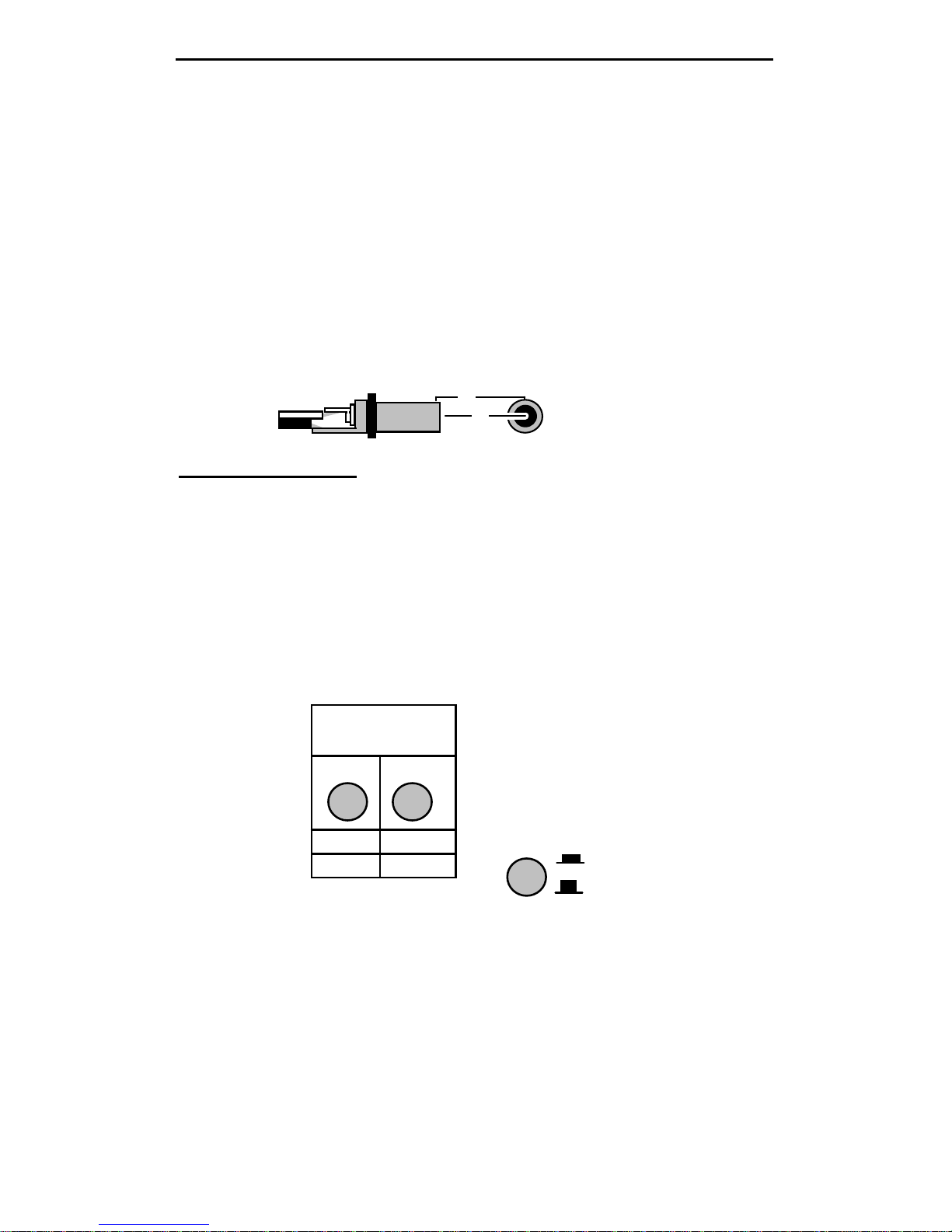
the display backlight is on. The unit's external power jack is located on
the front panel and accepts a standard 2.1-mm power plug. Positive
voltage (+) must be applied to the connector's center pin.
+
-
+
-
2.1 mm
Important Warnings: Reverse polarity or excessive voltage could
permanently damage the MFJ-266B! To avoid damage:
1. Never connect an AC transformer or positive-ground power source
2. Never install or remove batteries with external power connected
3.0 OPERATING MODE
Once you have suitable power (battery or external), you're ready to
explore the analyzer's basic operating features. Begin by pressing the red
PWR button on.
BAND-MODE
SELECT
Up Down
ANT Counter
Bk Lite
PWR
ON
OFF
3.1 Display Backlight
When the analyzer comes on, the screen displays a brief 1-second prompt
before automatically switching to the main menu. This prompt allows
you to turn on the optional display backlight. If you elect to use it, press
the Up button immediately, before the screen changes to the main menu
and hold it down until the backlight comes on. If you ignore the prompt,
the backlight will remain off. Off is the default setting to reduce battery
drain.
MFJ-266B HF/VHF/UHF Antenna Analyzer Instruction Manual
2012 MFJ Enterprises, Inc. Version 1D 4
3.2 Main Menu Screen
The main menu screen has two purposes:
(1.) Power Supply Voltage: Appears on the right side of the screen. If it
falls outside the 3.5 to 5V operating window of the battery packs, be sure
to change batteries or make power supply adjustments.
(2.) Operating Mode Prompt: On the left side of the screen. This
prompts you to select between the two primary operating modes (see
below).
D >FC DC:12.00V
U >ANT Analyzer
Supply Voltage"Down" for Counter
"Up" for Antenna Analyzer
(3.) (D >FC) Press the “Down” button to select Frequency Counter
mode.
(4.) (U > ANT Analyzer) Press the “Up” button to select the Antenna
Analyzer mode.
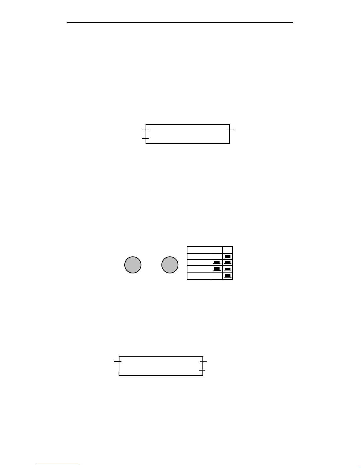
3.3 Frequency Counter Mode (D -> FC)
In this setup, the MFJ-266B functions as a 1-500 MHz frequency
counter. Note that the BAND SELECT switch B must be "up" in the HF
position for the counter mode to activate. If switch B is down, an error
message will prompt you to change the band setting to HF.
A
B
BAND SELECT
BAND A B
HF X
VHF
UHF
Counter X
UP
When a signal is applied to the Antenna jack, the frequency is displayed
in MHz. Two gate speeds are available. The default gate speed is Fast (or
Fg -- see the top right-hand side of the display). The fast gate provides 1kHz resolution. The alternative gate speed is Slow (or Sg), which
provides 100-Hz resolution. To change the gate speed:
(1.) For Fast Gate, press the UP button.
(2.) For Slow Gate: press the DOWN button.
Fg f: 010.000 MHz
REF FS: 100mV
Gate Speed
Frequency Readout
Relative Field Strength
The Counter mode also provides relative Field Strength (REF FS). This
feature is useful for conducting relative field-strength tests, estimating
input levels to the counter, and detecting local signals that could impact
SWR accuracy (see Section 7.2).
MFJ-266B HF/VHF/UHF Antenna Analyzer Instruction Manual
2012 MFJ Enterprises, Inc. Version 1D 5
3.4 Antenna Analyzer Mode (U -> ANT)
In this mode, the analyzer's built-in stimulus generator drives a bridge
circuit and the unit functions as a network analyzer. The top line of the
screen displays band selection (a single letter) and the operating
frequency in MHz (see Section-4). The bottom line simultaneously
displays complex impedance (Z = R+JX), impedance magnitude (Z =
Ω), and SWR for any load connected to the antenna jack. Note that only
SWR is displayed in the UHF operating range.
50+j 0 50 1.0
Stimulus Frequency
Band (Frequency) Selection
SWR (1.0:1)
10.000MHz D SWR
Impedance MagnitudeComplex Impedance
3.5 RF Signal Source
RF output from the MFJ-266B’s built-in stimulus generator is available
at the ANT connector in Analyzer mode. This signal is a +2 dBm
continuous carrier. When using the analyzer as a signal source, the
operating range, band, and frequency are selected in the normal manner
and will be displayed on the screen (see Frequency Selection, Section-4).
3.6 L/C Measurement Mode
The MFJ-266B may be used to measure the value of unknown capacitors
and inductors. To measure L/C values, connect the device to be tested to
the antenna jack and follow the procedure outlined below:
Measure Capacitance
Turn the analyzer off, then press and hold the Up button while turning
PWR back on. The screen will display the value in pF along with the
stimulus frequency being used for the measurement.
Measure Inductance
Turn the analyzer off, then press and hold the Down button while
turning PWR back on. The display will show inductance in uH along
with the stimulus frequency.
5.000MHz D C=
122 pF
Capacitance
Frequency Band
5.000MHz D L=
10.200 uH
Inductance
Frequency Band
5.000MHz D C=
Xc>1.5k
Frequency Band
Reactance out of Range
Change Stimulus Frequency
 Loading...