

HF/VHF SWR Analyzer
Model MFJ-259C
CAUTION: Read All Instructions Before Operating Equipment
MFJ ENTERPRISES, INC.
Tel: 662-323-5869 Fax: 662-323-6551
VERSION C1
INSTRUCTION MANUAL
300 Industrial Park Road
Starkville, MS 39759 USA
COPY RIG HT 201 3 MF J ENT ERP RISES, I NC.
C

MFJ-259C Instruction Manual HF/VHF SWR Analyzer
TABLE OF CONTENTS
1.0 INTRODUCTION........................................................................................................................................1
1.1 A Quick Word about Accuracy................................................................................................. 1
1.2 Typical Uses............................................................................................................................2
1.3 Frequency Range.....................................................................................................................2
2.0 POWER SOURCES ..................................................................................................................................... 2
2.1 External Power Supply............................................................................................................. 3
2.2 Using Internal Batteries ...........................................................................................................3
2.3 Using Rechargeable “AA” Type Batteries ................................................................................3
2.4 Using Conventional “AA” Drycell Batteries.............................................................................4
2.5 “Power Saving” Mode (sleep mode).........................................................................................4
3.0 MAIN MENU AND DISPLAY....................................................................................................................4
3.1 General Connection Guidelines................................................................................................4
3.2 Power-up Display.....................................................................................................................5
3.3 Main MODE descriptions........................................................................................................5
3.4 Blinking “VOLTAGE LOW” display warning.........................................................................6
4.0 MAIN (OR OPENING) MODE....................................................................................................................7
4.1 General Connection Guidelines................................................................................................7
4.2 Antenna SWR.......................................................................................................................... 7
4.3 Coax Loss................................................................................................................................9
4.4 Capacitance .............................................................................................................................9
4.5 Inductance ...............................................................................................................................10
5.0 ADVANCED OPERATION.........................................................................................................................11
5.1 Forward...................................................................................................................................11
5.2 General Connection Guidelines................................................................................................12
5.3 (Magnitude of) Impedance mode..............................................................................................12
5.4 Return Loss and Reflection Coefficient mode...........................................................................13
5.5 Distance to Fault mode ............................................................................................................ 13
5.6 Resonance Mode......................................................................................................................14
5.7 Percentage Transmitted Power................................................................................................. 14
6.0 ADJUSTING SIMPLE ANTENNAS............................................................................................................14
6.1 Dipoles.................................................................................................................................... 14
6.2 Verticals .................................................................................................................................. 15
6.3 Tuning a simple antenna..........................................................................................................15
7.0 TESTING AND TUNING STUBS AND TRANSMISSION LINES .............................................................16
7.1 Testing Stubs...........................................................................................................................16
7.2 Velocity Factor of Transmission Lines.....................................................................................16
7.3 Impedance of Transmission Lines or Beverage antennas..........................................................17
7.4 Adjusting Tuners.....................................................................................................................18
7.5 Adjusting Amplifier Matching Networks .................................................................................18
7.6 Testing RF Transformers.........................................................................................................19
7.7 Testing Baluns.........................................................................................................................19
7.8 Testing RF Chokes...................................................................................................................20
8.0 TECHNICAL ASSISTANCE.......................................................................................................................20
ii

MFJ-259C Instruction Manual HF/VHF SWR Analyzer
1.0 INTRODUCTION
Attention: Read Section-2.0 before attempting to use your analyzer. Incorrect power
supply voltages or excessive external voltage applied to the Antenna connector will
damage it!
Description
The MFJ-259C is a compact battery powered RF impedance analyzer that combines four basic circuits; a 50-ohm
bridge, eight-bit micro-controller, frequency counter, and a 0.53-230 MHz variable-frequency oscillator with
switched coverage of nine overlapping bands. These four sub-elements are integrated to provide a wide variety of
useful antenna and impedance measurements including coaxial cable loss and distance to an open or short.
Although designed primarily for analyzing 50-ohm antennas and transmission line systems, the MFJ-259C also
measures RF impedance from a few ohms to several hundred ohms. In addition, it functions as a discrete signal
source (RF-Signal Generator) and independent frequency counter.
1.1 A Quick Word about Accuracy
Inexpensive impedance meters have limitations. The main causes of measurement error are:
(1.) Signal ingress from external RF sources
(2.) Component limitations
(3.) Stray reactance from connectors, pc traces, and wires.
1.) Signal Ingress: Virtually all low-cost handhelds use simple broadband diode detectors. Unlike costly lab-grade
analyzers using frequency-selective receivers, broadband detectors admit out-of-band signals. Unfortunately, the
offending interference can't be filtered out using common low-pass or band-pass circuitry because the L/C elements
would act like lengths of transmission line and transform the impedance readings as a function of frequency.
Increasing generator power output can, in some instances, overpower interfering signals, but the current needed to
deliver the additional RF power greatly reduces battery life. In fact, over 70% of the analyzer's 150-mA current
drain is already allocated to the VFO and its amplifier stages for generating a low-harmonic level-amplitude test
signal.
Most RF-interference problems occur at lower frequencies and are caused by high-power AM-broadcast stations.
These signals couple efficiently into large antenna arrays and are especially problematic for 160-meter verticals. In
the event you encounter intense local interference, we recommend using the MFJ-731 Tunable Analyzer Filter. It
is designed to attenuate off-frequency signals between 1.8 and 30 MHz without introducing significant errors.
2.) Component Limitations: At very low voltage levels, diode detectors become nonlinear, a condition that
reduces accuracy. The MFJ-259C minimizes this problem by using special microwave zero-bias Schottky detectors
with linearity enhanced by compensating diodes. Using this technique, each analyzer is individually optimized to
provide the highest accuracy possible with both high and low impedance loads, making the A/D converter's 8-bit
resolution the analyzer's primary accuracy limitation.
3.) Stray Reactance: The length of electrical connections between components within the bridge circuit, and the
line between the bridge and antenna connector, may introduce inaccuracy at higher frequencies and when the load
impedance is very high or very low. However, the MFJ-259C minimizes this problem with careful pc layout and by
using low-capacitance microwave-grade surface-mount components with virtually no lead length.
While some analyzers may display misleading "exact readings" falling outside the reliable measurable range, the
MFJ-259C does not. Instead, it is programmed to generate a display warning for out-of-range results. For example,
if (Z > 650) appears on your display, it means the impedance being measured is greater than 650 ohms and outside
the reliable measurement range.
1

MFJ-259C Instruction Manual HF/VHF SWR Analyzer
1.2 Typical Uses
The MFJ-259C may be used to adjust, test, or measure the following:
Antennas:.......................................SWR, impedance, reactance, resistance, resonant frequency, and bandwidth
Antenna tuners:............................SWR, bandwidth, frequency
Amplifiers: .....................................Input and output matching networks, chokes, suppressors, traps, and
components
Coaxial transmission lines:........SWR, length, velocity factor, approximate Q and loss, resonant frequency,
and impedance
Filters:.............................................SWR, attenuation, and frequency range
Matching or tuning stubs:..........SWR, approximate Q, resonant frequency, bandwidth, impedance
Traps:..............................................Resonant frequency and approximate Q
Tuned Circuits:.............................Resonant frequency and approximate Q
Small capacitors:..........................Value and self-resonant frequency
RF chokes and inductors:..........Self resonant frequency, series resonance, and value
Transmitters and oscillators:.....Frequency
The MFJ-259C measures and displays the following:
Cable length (feet) Impedance phase (degrees) Resonance (MHz)
Cable Loss (dB) Inductance (uH) Return loss (dB)
Capacitance (pF) Reactance or X (ohms) Signal Frequency (MHz)
Impedance or Z magnitude (ohms) Resistance or R (ohms) SWR (referenced to 50 ohms)
The MFJ-259C as a non-precision signal source:
VFO output is leveled at approximately 3-Vpp, or around 20 milliwatts into a 50-ohm load. This signal is
relatively pure with harmonics better than -25 dBc (dB below the fundamental-frequency carrier). The internal
source impedance (Zo) is 50 ohms.
A more complete description of the MFJ-259C's features along with proper measurement methods can be found by
reading sections covering the particular measurement you wish to make. Consult the table of contents for various
applications.
1.3 Frequency Range
The MFJ-259C covers 0.53 to 230 MHz without frequency gaps using a precision reduction-drive VFO tuning
capacitor and two band switches. Bands of coverage are:
Main Switch: 155-230 MHz 113-155 MHz 67-113 MHz 28-67 MHz 11-28 MHz Lower Range
Lower Range Switch: 4.7-11 MHz 2.1-4.7 MHz 1.0-2.1 MHz 0.53-1.0 MHz
To select the bands above 11 MHz, turn the Main Switch to the band desired. For the bands below 11 MHz, turn
the Main Switch to Lower Range and select the desired band using the Lower Range switch.
2.0 POWER SOURCES
Please read this entire section before connecting your analyzer to any power source. Improper
connections or incorrect voltages may cause permanent damage to your analyzer!
2
MFJ-259C Instruction Manual HF/VHF SWR Analyzer
2.1 External Power Supply
MFJ offers an optional power supply, the MFJ-1312D, that satisfies all external supply requirements. We
strongly recommend using this supply. If you use a different power source, note that the voltage output must be
greater than 11 volts and less than 16 volts when the analyzer is powered on and running (loaded power source).
The maximum voltage in Sleep Mode (unloaded power source) should never exceed 18 volts. AC adapters must be
well filtered and the plug must have a grounded sleeve and positive center lead. The ideal voltage-source
specification is 14.5 VDC at 150 mA. Confirm your supply can deliver this output level safely without overheating
or introducing excessive AC ripple.
Please read the battery installation instructions (Section 2.3) if you plan to install batteries. Never connect
external DC power if non-rechargeable batteries are installed and the battery charger is enabled. Permanent
damage could result!
+
-
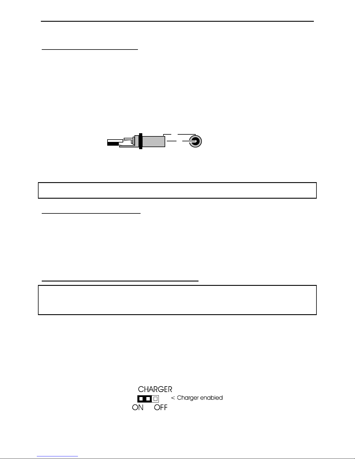
The MFJ-259C has a recessed 2.1 mm power jack located on the top-right-hand side of the unit. It is labeled Power
13.8 VDC. The jack's outside barrel contact is negative and the center pin is positive. Inserting a power plug into
the power jack automatically disables the internal batteries as a power source. However, the batteries will be
trickle charged if the charger circuit is enabled.
IMPORTANT WARNING: Reverse Polarity Or Excessive Voltage Can Damage Or Destroy The MFJ-259C.
Never Apply More Than 18 Volts, Never Use AC-output or Positive Ground Supplies!
+
2.1 mm
2.2 Using Internal Batteries
Before installing batteries for the first time, check the position of the Charger Jumper. To gain access, remove the
eight screws securing the analyzer's back cover and separate it from the unit. Look for a 3-pin header with a small
black-plastic shorting plug that fits over two of its pins. It is located at the top of the main pc board near the OFF-
ON switch and power connector. The shorting plug must be properly positioned for the type of battery you intend
to use (either rechargeable or non-rechargeable). While you have the analyzer's case removed, you may install
batteries into their tray -- or install them later by removing the battery-tray door that is attached to the rear of the
case with two screws.
2.3 Using Rechargeable “AA” Type Batteries
IMPORTANT WARNING: Do not use an external power sources that deliver less than 13.8 volts with
rechargeable batteries installed. If the external supply voltage is too low, the charger will not work properly and
batteries will eventually discharge. We recommend charging batteries with the MFJ-259C power switch off and
allowing enough charging time to establish full battery charge. A minimum of ten hours is recommended.
When using rechargeable batteries, your power source must deliver a minimum of 13.8 volts to meet the minimum
charge-voltage threshold. Typical charging current is 10-20 mA (trickle-charge rate). The charger circuit functions
any time external power is connected, even when the analyzer is turned off. Again, the MFJ-1312D supply fulfills
all power supply and charging requirements for the MFJ-259C and is recommended.
When using rechargeable batteries, the internal black plastic jumper must be set to the proper position. If it is
not set properly, the batteries will not charge. As described above, the jumper is located inside the analyzer, near
the external power jack on the back side of the circuit board.
For rechargeable batteries, set the jumper as shown below:
3

MFJ-259C Instruction Manual HF/VHF SWR Analyzer
2.4 Using Conventional “AA” Drycell Batteries
Whenever possible, install a fresh matched set of high-quality alkaline batteries. Conventional zinc cells will work,
but alkaline batteries offer a lower risk of damage caused by leakage. Alkaline cells also provide longer running
time and superior shelf life. When using any non-rechargeable dry-cell battery, always remove them immediately
when they become weak to avoid damage from leakage. Also, never store your analyzer for extended periods
(longer than a month) with non-rechargeable batteries installed.
IMPORTANT WARNING: When Using Non-Rechargeable Batteries, The Analyzer's Internal Charging System
Must Be Defeated! To Defeat The Charger, Set The Internal Jumper To The Charger-Off Position, As Shown
Below:
2.5 “Power Saving” Mode (sleep mode)
The analyzer's current drain is normally around 150 mA, which places a moderate demand on the battery pack.
You can extend the analyzer's running time significantly by using the internal Sleep Mode power-saving function.
In Sleep Mode, the analyzer's RF-generator shuts down and battery drain drops to under 15 mA. Any time Sleep
Mode is activated, the analyzer operates with a two-minute inactivity window. During any 2-minute period, you
must actuate the Mode switch -- or adjust the frequency by more than 50 kHz -- at least once for the analyzer to
remain awake. Any time a two-minute inactivity period elapses, the power saving circuit automatically switches in.
When the analyzer goes to sleep, a blinking SLP message will appear in the display’s lower right corner, as shown
below:
To reawake the unit, momentarily press either the Mode or Gate button.
To Disable Sleep mode:
(1.) Turn the analyzer off.
(2.) Press and hold the Mode button while reapplying power.
(3.) Continue holding the Mode button until the copyright message appears on the screen.
(4.) Release Mode. If Sleep Mode was disabled successfully, the message shown below will appear on-screen. The
Sleep Mode function becomes re-enabled anytime the analyzer is turned Off and On again.
3.0 MAIN MENU AND DISPLAY
IMPORTANT WARNING: Never Apply RF or any other external voltage to the Antenna port of this
unit. The MFJ-259C uses zero bias detector diodes that may be damaged by external voltages. Read
Section-2.0 before applying power! Incorrect supply voltages will also damage this unit.
3.1 General Connection Guidelines
1.) Antenna Jack: When making RF measurements, connect your Device Under Test (DUT) to the SO-239
connector located on the top of the case. You'll use this port for SWR and all other RF measurements excluding the
Frequency Counter function.
4
MFJ-259C Instruction Manual HF/VHF SWR Analyzer
2.) Power connector: (2.1 mm type) is described in Section 2.0. Be sure to read Section-2.0 before operating your
unit. Using an incorrect power sources can permanently damage the analyzer.
3.) Frequency Counter Input: BNC connector used for frequency-counter functions only.
3.2 Power-up Display
After turning on the Power switch (or after applying external power with the switch on), a sequence of three
message screens appear on the display.
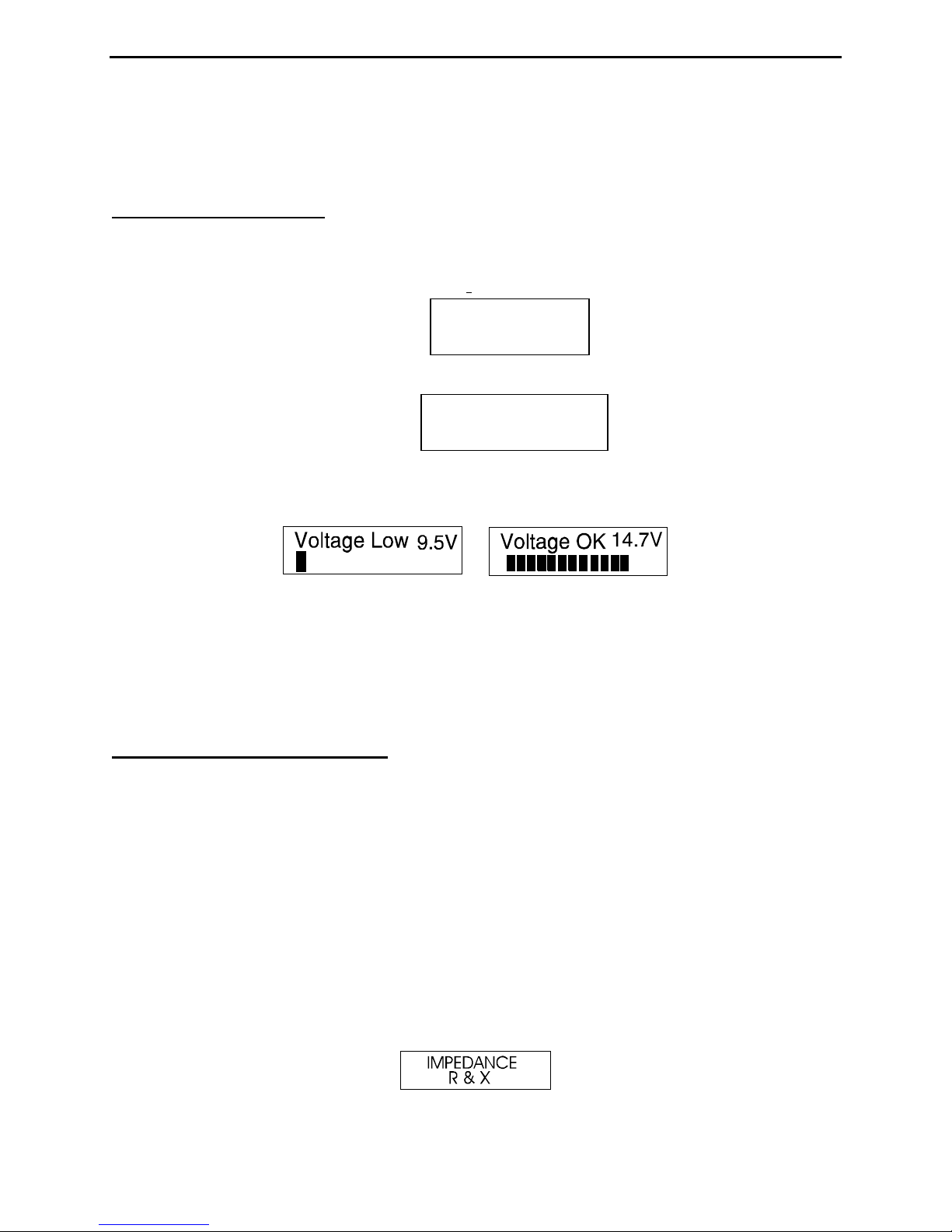
The first screen presents the analyzer's software version (VER).
The second message shows the software copyright symbol.
MFJ-259C
VER 13.40
MFJ-Enterprises
(c)
The third message provides a power-source check, displaying the internal battery or external power supply voltage
level along with a warning if the source is too low to support reliable operation.
The fourth and final power-up display is the working screen for the analyzer’s default operating mode, as described
in Section 3.2 (SWR, Impedance R&X). The two analog panel meters also become active, displaying SWR and
Impedance Magnitude (Z) measurements for the DUT.
The MFJ-259C has five (5) Basic Operating Modes that are used for conducting a variety of measurements. If you
tap (momentarily press) the Mode button, the analyzer steps to the next Mode selection. The five main modes and
their opening screens are described in Section-3.3 below:
3.3 Main MODE descriptions
Press the Mode switch to scroll through the analyzer's five operating modes. By "scrolling", we mean that each tap
of the mode switch will step the analyzer ahead to the next menu selection. Each new selection comes up on the
display with an Identifier Screen. After 3 seconds, the Identifier Screen is replaced by the mode's working screen.
The menu is circular, so after sequencing through all five choices, the sequence starts over. The five basic
operating modes are described in detail below:
1.) Impedance R&X (Initial Mode): Use this mode for measuring SWR and complex impedance. The Impedance
R&X mode is the analyzers "default" mode because it is the one most frequently used for routine antenna
adjustments. The top line of the working display shows the VFO Frequency in MHz and the numerical SWR
reading. The lower line displays the Resistive (R) and Reactive (X) impedance components for the attached
load. Pressing and holding the Gate button in this mode displays the Impedance Magnitude (Z) and Phase
Angle (Ø). The analog Impedance meter also displays Impedance Magnitude (Z), and the SWR meter displays
Standing Wave Ratio (SWR). The analog meters are especially useful when tuning continuously adjustable
circuits such as an ATU or matching networks. The identifier screen for the Impedance R & X mode is shown
below:
5
MFJ-259C Instruction Manual HF/VHF SWR Analyzer
2.) Coax Loss: Use the analyzer's second mode to measure loss incurred in random lengths of 50-Ohm cable, 50-
Ohm attenuator pads, 50-Ohm transformers, and 50-Ohm baluns. The top working-display line shows the
VFO Frequency in MHz and the lower line presents the measured Loss in dB. Note that the transmission line
or device under test must be unterminated at its far end during loss testing. If a load or resistive
termination is installed, the measured loss will be significantly higher than the actual loss. Note that this
measurement mode only works for lines or devices carrying differential currents.
3.) Capacitance in pF: Use this mode for checking unknown capacitor values (in pF) and for determining how
much reactance a component exhibits at a particular frequency (Xc in ohms). In Capacitance Mode, the top
line of the working display shows the VFO Frequency in MHz and the measured Capacitive Reactance (Xc) at
the VFO frequency (in ohms). The lower line shows the measured capacitance (C) in picofarads (pF). The
analog Impedance meter also displays Xc reactance in ohms.
4.) Inductance in uH: In Inductance Mode, the top line of the working display shows the VFO Frequency in MHz
and the capacitive reactance (XL) at the VFO frequency (in ohms). The lower line shows the measured
inductance (L) in microhenries (µH). The Impedance meter displays reactance in ohms.
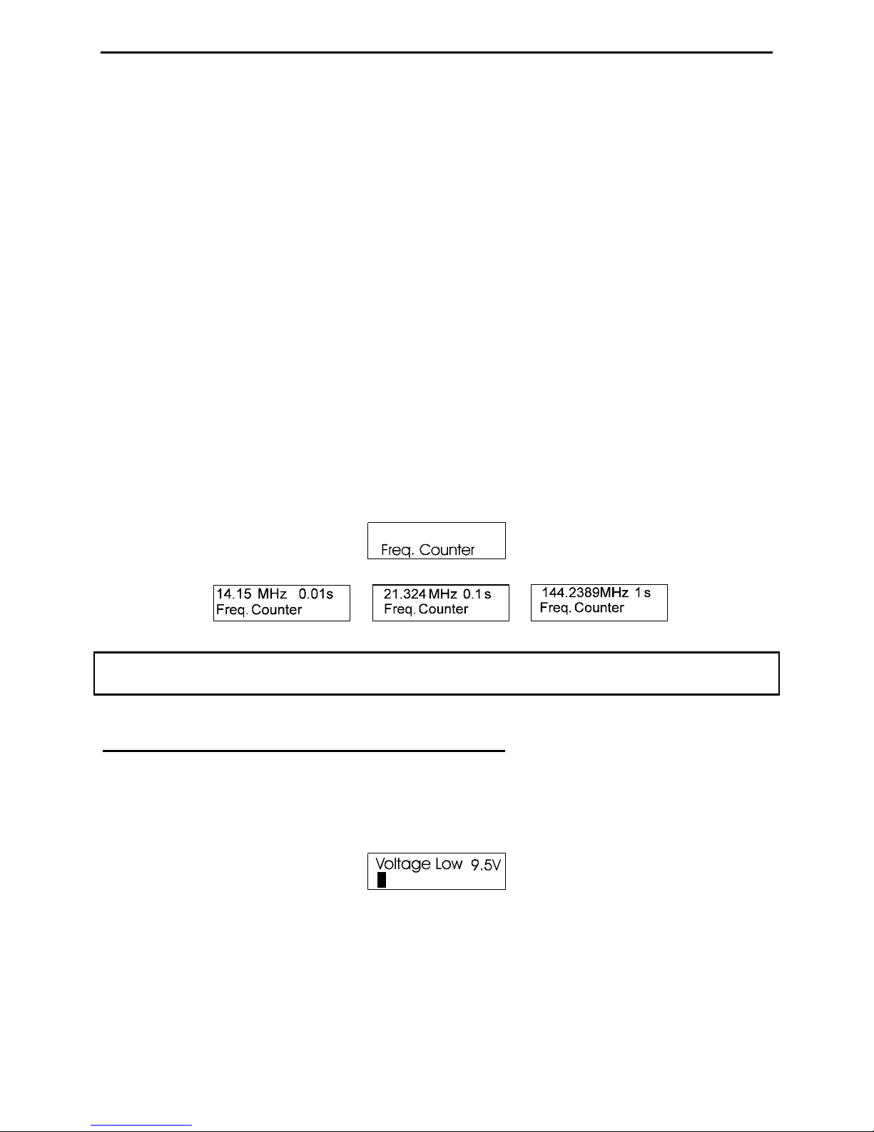
5.) Frequency Counter: The fifth mode converts the analyzer into a discrete frequency counter. Connect the RF
source (DUT) to the BNC connector labeled Frequency Counter Input. As with many counters, the sensitivity
threshold for a locked-in reading gradually decreases with increasing frequency. The measurement threshold
at 0.53 MHz is around 10 millivolts -- and this level gradually increases to around 200 millivolts at 230 MHz.
The "never exceed" limit for safe testing is 2-volts peak-to-peak. The counter's default gate time is 0.1
second, but you may reset it to either .01 second (very fast) or 1.0 second (very slow) by tapping the Gate
button. A 1.0-second gate times provide increased frequency resolution (more digits to the right of the decimal
point), and the .01 gate provides very fast response with less resolution (see sample screens below):
IMPORTANT WARNING: Never apply more than two volts of peak voltage -- or any dc voltage -- to
the Frequency Counter BNC port.
3.4 Blinking “VOLTAGE LOW” display warning
If the external dc source or battery voltage drops below 11 volts, a blinking Voltage Low warning will come up on
the display. Pressing Mode during a low-voltage warning will disable it and allow you to continue testing.
Caution: Measurements made with supply voltages below 11 volts may not be as reliable.
6
 Loading...