

MFJ MFJ-207 User Manual
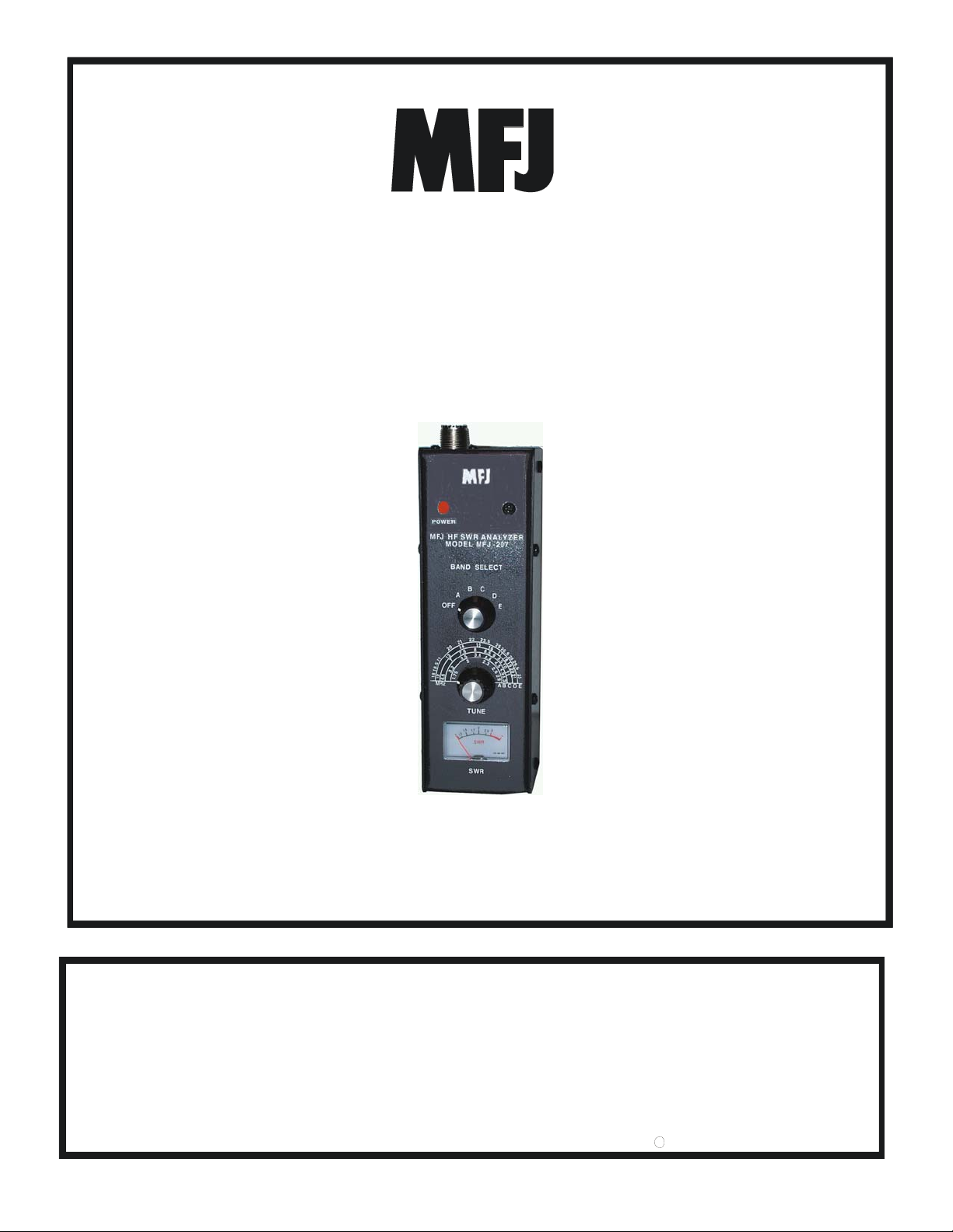
HF 10-160M SWR Analyzer
Model MFJ-207
INSTRUCTION MANUAL
VERSION 0B
CAUTION: Read All Instructions Before Operating Equipment
MFJ ENTERPRISES, INC.
300 Industrial Park Road
Starkville, MS 39759 USA
Tel: 662-323-5869 Fax: 662-323-6551
COPYRIGHT 2006 MFJ ENTERPRISES, INC.
C

MFJ-207 Instruction Manual HF 10-160M SWR Analyzer

MFJ-207 Instruction Manual HF 10-160M SWR Analyzer
DISCLAIMER
Information in this manual is designed for user purposes only and is not intended to supersede information
contained in customer regulations, technical manuals/documents, positional handbooks, or other official
publications. The copy of this manual provided to the customer will not be updated to reflect current data.
Customers using this manual should report errors or omissions, recommendations for improvements, or other
comments to MFJ Enterprises, 300 Industrial Park Road, Starkville, MS 39759. Phone: (662) 323-5869; FAX:
(662) 323-6551. Business hours: M-F 8-4:30 CST.

MFJ-207 Instruction Manual HF 10-160M SWR Analyzer
TABLE OF CONTENTS
TOPIC PAGE
1. TABLE OF CONTENTS 2
2. LIST OF FIGURES AND TABLES 2
3. INTRODUCTION AND FEATURES 3
4. USES FOR THE MFJ-207 4
5. SYSTEM CONTROLS AND INDICATORS 5
6. THEORY OF OPERATION 7
7. MFJ-207 EASY-START INSTRUCTIONS 8
8. IN CASE OF DIFFICULTY 17
9. TECHNICAL ASSISTANCE 17
APPENDICES
A. ZERO BEATING AGAINST A RECEIVER 14
B. FREQUENCY/SWR PLOTTING CHART 15
C. SWR AT TRANSMITTER VS. SWR AT ANTENNA 16
LIST OF FIGURES
Figure 1 Front Panel Jacks and Controls 5
Figure 2 End Panel Jacks 6
Figure 3 Block Diagram 7
Figure 4 MFJ-207 to Tuner Hook Up 10
Figure 5 Schematic Diagram 13

MFJ-207 Instruction Manual HF 10-160M SWR Analyzer
INTRODUCTION:
The MFJ-207 gives you a direct readout of your antenna’s SWR without the need for formulas or indirect
readings. The MFJ-207 can also be used to adjust a tuner to match your antenna without the need for
transmitting. The frequency coverage for the MFJ-207 is from below 1.75 MHZ to Above 30 MHZ in 5 user
selectable bands.
FEATURES
Portable – The MFJ-207’s light weight, small size and internal battery capability makes it great for Field Day,
Travel or any time you need to check out a new antenna installation quickly easily.
Accurate – The Bridge Circuit uses precision resistors for utmost in accuracy.
Great Value – The MFJ-207’s low cost puts a great instrument in your hands for those who only need to adjust
their antennas occasionally.
Stable – With built in AGC the MFJ-207 is accurate across the bands. No false readings.
Rugged Construction: Attractive all-metal cabinet, conservative component selection and extensive RF
filtering ensure solid performance for years to come. Fully covered by MFJ’s “No Matter What” one year
limited warranty.
Before attempting to operate your MFJ-207, please read the manual thoroughly. It contains important detail
about setting up your unit to obtain the best performance.
USES FOR THE MFJ-207 HF 10-160M SWR ANALYZER
Your MFJ-207 SWR ANALYZER has many uses. It can be used to find the resonant frequency of your
antenna, to find the SWR of your antenna at a particular frequency, and to find the frequency at which your
antenna has the lowest SWR. You can also use the SWR Analyzer to adjust your antenna to a low SWR and to
adjust an antenna tuner to match the transmitter to your transmission line. You can even find out if your
antenna is resonant on more that one frequency.
Measurement of the antenna’s SWR is done right at the input to the transmission line. There is no need to
climb the tower and measure the SWR at the antenna. Also handy for suspended dipoles. Using the chart in
Appendix C and knowing the line loss for your transmission line and the SWR at the line input, you can
determine the SWR at the antenna, regardless of line length.
MFJ-207 Instruction Manual HF 10-160M SWR Analyzer
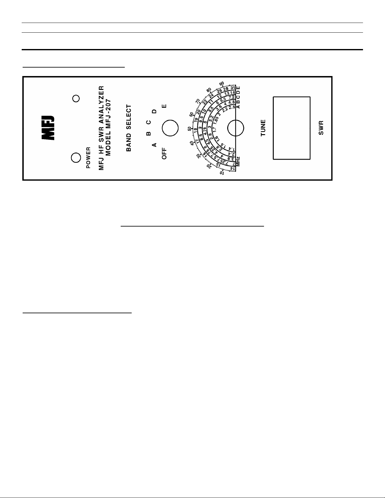
SYSTEM CONTROLS AND INDICATORS
Front Panel Jacks and Controls
1 2 3 4
FIGURE 1: Front Panel Jacks and Controls
1. Power On LED: Instantly know if the MFJ-207 is on or off with this bright LED.
2. Band Select Switch: This 6 position switch turns the power on and selects any one of
five over lapping bands.
3. Tune Control: This variable capacitor instantly sweeps across the desired band to
find that SWR fast and easy.
4. SWR Meter: Direct readout of your SWR from 1:1 to Infinity.
Frequency Coverage of the Bands
NOTE: The frequency coverage may vary slightly from this chart and the label on the cover of the unit and is
for reference only. A frequency counter can be connected to the Freq. Out connector shown in Figure 2 to get a
more accurate reading of the frequency. As an alternative to a frequency counter you can Zero Beat the output
with an HF receiver. See Appendix A.
BAND A: 1.40 - 2.50 Mhz
BAND B: 2.40 - 4.50 Mhz
BAND C: 3.90 - 7.20 Mhz
BAND D: 7.00 - 14.00 Mhz
BAND E: 14.00 - 31.00 Mhz
 Loading...