


End-Fed H orizontal
Wire Antennas
Models:
MFJ-1982LP/ MP/ HP
MFJ-1984LP/ MP/ HP
VERS ION 1A
INSTRUCTION MANUAL
CAUTION: Read All Instructions Before Operating Equipment
MFJ ENTERPRISES, INC.
300 Industrial Park Road
Starkville, MS 39759 USA
Tel: 662-323-5869 Fax: 662-323-6551
COPYRIGHT 2017 M FJ ENT ERPRIS ES, INC.

MFJ-1982LP/MP/HP and MFJ-1984LP/MP/HP
Instruction Manual
General Description
General Description: End-Fed Horizontal Wire antennas (or EFHWs) cover
multiple bands without traps, stubs, or resonators. End-fed wires resonate on
their 1/2-wave fundamental frequency plus all odd and even harmonics above.
By adding a broad-band matching network, the wire's high impedance feed point
is transformed down to 50 ohms across a wide frequency range and, in most
cases, you won't need a tuner to operate. Note that the single-wire radiator may
be installed using only one high center or end support, making it fast and easy to
set up at home, on the road, or as a "grab-and-go" emergency antenna.
Models
Six versions of this antenna are available, allowing you to pick the one best
suited for your application.
[ ] MFJ-1982LP: 30-watts PEP, 80-10 meters
[ ] MFJ-1982MP: 300-watts PEP, 80-10 meters
[ ] MFJ-1982HP: 800-watts PEP, 80-10 meters
[ ] MFJ-1984LP: 30-watts PEP, 40-10 meters
[ ] MFJ-1984MP: 300-watts PEP, 40-10 meters
[ ] MFJ-1984HP: 800-watts PEP, 40-10 meters
All MFJ-1982 models come with 132 feet of antenna wire and cover 80, 40, 30,
20, 17, 15, 12, and 10 meters. The only difference between the LP, MP, and HP
version is the power rating of the matching network. The MFJ-1982 resonates
slightly above the 30-meter band, so a tuner is normally needed for transmitting.
Also, note that there is small 6-turn inductor wound into the antenna wire about
6-feet from the matching unit.
All MFJ-1984 models come with 66 feet of wire and cover 40, 30, 20,15, and 10
meters. Note that 17 and 12 Meters are not covered because they are not
harmonically related to the shorter wire length.
Power Rating
All ratings are in Watts-PEP using the SSB or CW mode and transmitting 50% of
the time or less per the ICAS (Intermittent Commercial and Amateur Standard).
These ratings do not apply to long key-down power applications where the
matching network could overheat. De-rate accordingly for these modes.
Installation Instructions
Supports: Install the antenna wire using one or more high supports (typically
tree limbs). Note that the "no-snag" end insulator is especially shaped to slide
through branches in both directions to make installation and take-down easier.
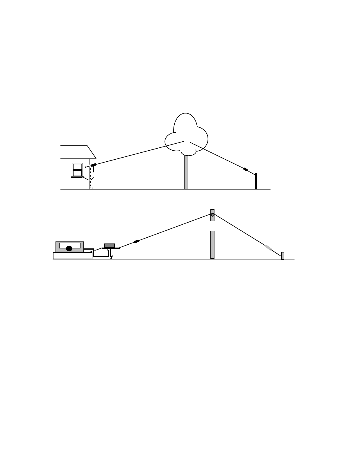
Typical Residential Setup:
Antenna Wire
Matching Network
Coax
Safety
Ground
Tall
Support
Insulator
Tie-off
Typical Portable Setup:
Antenna Wire
Radio
Coax
Network
Coil
Ground
Tall
Support
Insulator
Tie-off
Grounding
Always install a safety ground using a temporary or permanent ground rod. If you
can't install a rod, make a counterpoise with using 15 or 20 feet of wire and
spread it out beneath the feed point. The driving resistance at the antenna's feed
point is very high, so your ground need not be perfect in order to reference the
cold end of the matching transformer to earth. Grounding provides an alternate
return path, reducing the probability of common-mode RF energy finding its way
back to your radio via the outside of the coax shield.
Feedline
Use any suitable 50-ohm coaxial cable to feed your antenna. As a rule, it's best
to keep the feed line as short as possible. When a longer run is necessary, route
coax along the ground rather than suspended in the air. Also, do not install ferrite
beads or a current style choke-balun at the input of the antenna matching
network -- the blocking impedance won't be high enough to be effective. Better to

have the coax shield and transformer referenced as closely as possible to RF
ground.
When you install the coax, allow it to hang below the matching unit so its weight
can orient the weather cover facing up and the air vents facing down.
Snag-Resistant End Insulator
The attached "backpacker" insulator is especially designed to prevent snagging
on branches and becoming stuck during installation or take-down (if you prefer,
you may replace it with any conventional insulator). Use half-hitches or a ship
knot when attaching the support halyard and tape down the end to allow the
insulator to slide freely in both directions.
Supports
Black polyester or parachute cord works well (not supplied, but available from
MFJ). As previously noted, the coax feed and the ground wire should hang below
the matching network to orient the suspended matching network with its weather
cap up and the air vents facing down. Also, as noted, do not allow the antenna to
contact combustible materials or surfaces if you plan to run a high-power
amplifier!
Matching Network Vents
The impedance ratio of the EFHW matching network is very high (49:1), so there
will be some inherent loss. As a result, some of your transmitted power will be
dissipated as heat in the transformer. While there's not enough loss to noticeably
detract from your signal strength, it will cause the transformer's ferrite core to
warm during transmissions -- especially at high power levels. To ensure
adequate cooling, always mount the matching network in the clear and
periodically inspect the screened vents, brushing away any accumulated debris
from the openings

In Case Of Trouble
1. Lowest SWR out-of-band: If all minimum-SWR points trend above or below
the desired band allocations, you may adjust it by changing the wire length.
Shorten to increase frequency and lengthen to lower frequency. For all MFJ-1982
models, be sure to make any length adjustments at the far end of the wire to
avoid changing the spacing between the compensating coil and the matching
network.
2. Abrupt SWR changes while transmitting: If the matching transformer core is
allowed to overheat and reach Curie temperature, the toroid permeability will
change abruptly and create a severe mismatch. In most cases, when the core
cools, normal operation will be restored. However, take this event as a warning to
reduce transmitter power or shorten the duration of your transmissions. Also,
repeated overheating can permanently alter the permeability of the matching
transformer core, rendering it unusable.
Important Warning: If you experience a sudden change in SWR, stop
transmitting immediately and allow the matching transformer to cool for at
least 30 minutes. Then, adjust your operating power or transmission time
accordingly!
3. "RF in the Shack": If you use a longer feed line (more than 10 or 15 feet),
ground the matching network and your station equipment separately. Also, where
possible, run feed line along the ground rather than suspended above it.

FULL 12-MONTH WARRANTY
MFJ Enterprises, Inc. warrants to the original owner of this product, if manufactured by MFJ
Enterprises, Inc. and purchased from an authorized dealer or directly from MFJ Enterprises, Inc.
to be free from defects in material and workmanship for a period of 12 months from date of
purchase provided the following terms of this warranty are satisfied.
1. The purchaser must retain the dated proof-of-purchase (bill of sale, canceled check, credit
card or money order receipt, etc.) describing the product to establish the validity of the warranty
claim and submit the original or machine reproduction of such proof of purchase to MFJ
Enterprises, Inc. at the time of warranty service. MFJ Enterprises, Inc. shall have the discretion to
deny warranty without dated proof-of-purchase. Any evidence of alteration, erasure, of forgery
shall be cause to void any and all warranty terms immediately.
2. MFJ Enterprises, Inc. agrees to repair or replace at MFJ's option without charge to the
original owner any defective product provided the product is returned postage prepaid to MFJ
Enterprises, Inc. with a personal check, cashiers check, or money order for $10.00 covering postage
and handling.
3. MFJ Enterprises, Inc. will supply replacement parts free of charge for any MFJ product
under warranty upon request. A dated proof of purchase and a $8.00 personal check, cashiers
check, or money order must be provided to cover postage and handling.
4. This warranty is NOT void for owners who attempt to repair defective units. Technical
consultation is available by calling (662) 323-5869.
5. This warranty does not apply to kits sold by or manufactured by MFJ Enterprises, Inc.
6. Wired and tested PC board products are covered by this warranty provided only the
wired and tested PC board product is returned. Wired and tested PC boards installed in the
owner's cabinet or connected to switches, jacks, or cables, etc. sent to MFJ Enterprises, Inc. will be
returned at the owner's expense unrepaired.
7. Under no circumstances is MFJ Enterprises, Inc. liable for consequential damages to
person or property by the use of any MFJ products.
8. Out-of-Warranty Service: MFJ Enterprises, Inc. will repair any out-of-warranty product
provided the unit is shipped prepaid. All repaired units will be shipped COD to the owner. Repair
charges will be added to the COD fee unless other arrangements are made.
9. This warranty is given in lieu of any other warranty expressed or implied.
10. MFJ Enterprises, Inc. reserves the right to make changes or improvements in design or
manufacture without incurring any obligation to install such changes upon any of the products
previously manufactured.
11. All MFJ products to be serviced in-warranty or out-of-warranty should be addressed to
MFJ Enterprises, Inc., 300 Industrial Park Rd, Starkville, Mississippi 39759, USA and must be
accompanied by a letter describing the problem in detail along with a copy of your dated proof-ofpurchase and a telephone number.
12. This warranty gives you specific rights, and you may also have other rights, which vary
from state to state.

DISCLAIMER
Information in this manual is designed for user purposes only and is not
intended to supersede information contained in customer regulations, technical
manuals/documents, positional handbooks, or other official publications. The
copy of this manual provided to the customer will not be updated to reflect
current data.
Customers using this manual should report errors or omissions,
recommendations for improvements, or other comments to MFJ Enterprises, 300
Industrial Park Road, Starkville, MS 39759. Phone: (662) 323-5869; FAX: (662)
323-6551. Business hours: M-F 8-4:30 CST.

MFJ-1982/1984 Manual
MFJ ENTERPRISES, INC.
300 Industrial Par k Road
Starkville, MS 39759
Version 1A
Printed In U.S.A.
 Loading...