

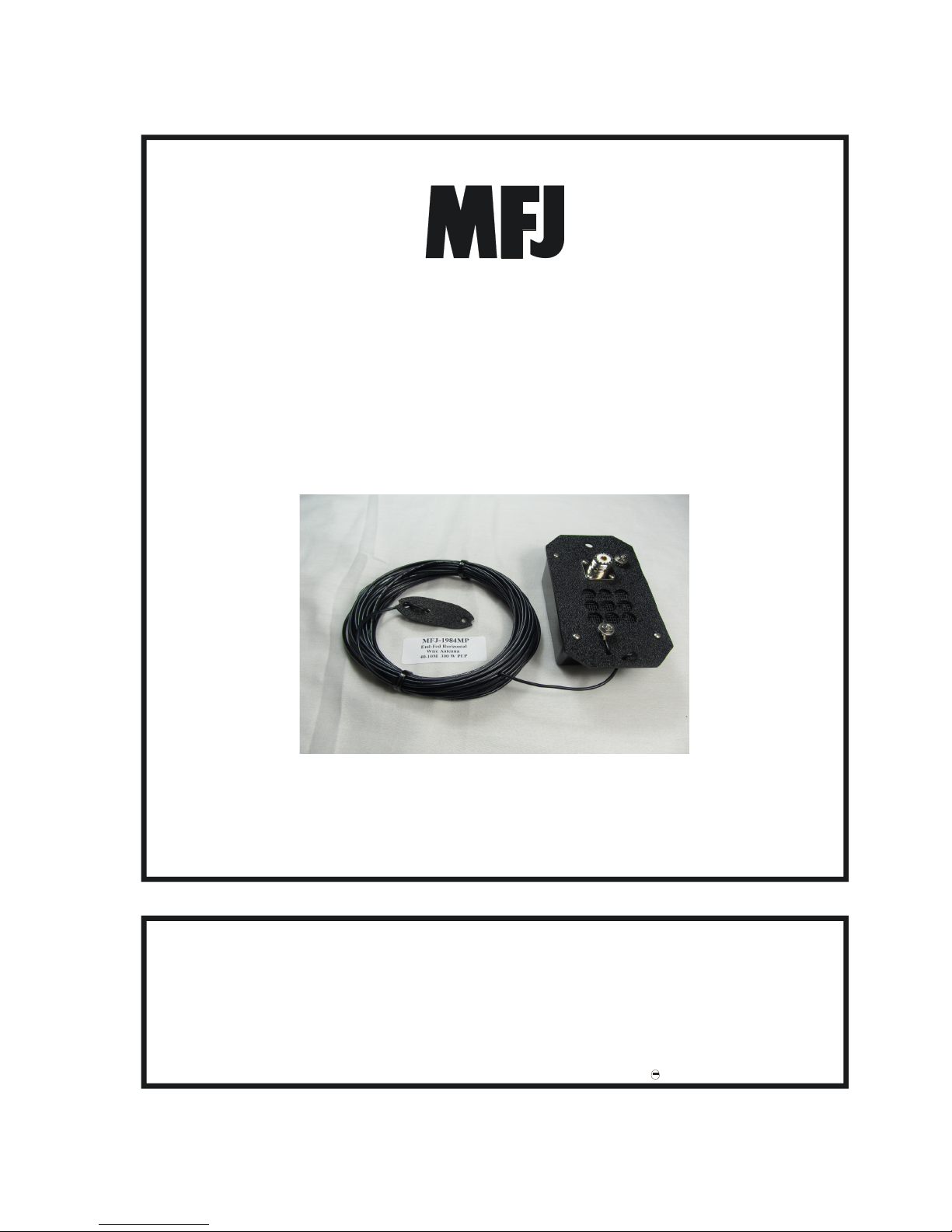
End-Fed H orizontal
Wire Antennas
Models:
MFJ-1982LP/ MP/ HP
MFJ-1984LP/ MP/ HP
CAUTION: Read All Instructions Before Operating Equipment
MFJ ENTERPRISES, INC.
VERS ION 1A
INSTRUCTION MANUAL
300 Industrial Park Road
Starkville, MS 39759 USA
Tel: 662-323-5869 Fax: 662-323-6551
COPYRIGHT 2017 M FJ ENT ERPRIS ES, INC.

MFJ-1982LP/MP/HP and MFJ-1984LP/MP/HP
Instruction Manual
General Description
General Description: End-Fed Horizontal Wire antennas (or EFHWs) cover
multiple bands without traps, stubs, or resonators. End-fed wires resonate on
their 1/2-wave fundamental frequency plus all odd and even harmonics above.
By adding a broad-band matching network, the wire's high impedance feed point
is transformed down to 50 ohms across a wide frequency range and, in most
cases, you won't need a tuner to operate. Note that the single-wire radiator may
be installed using only one high center or end support, making it fast and easy to
set up at home, on the road, or as a "grab-and-go" emergency antenna.
Models
Six versions of this antenna are available, allowing you to pick the one best
suited for your application.
[ ] MFJ-1982LP: 30-watts PEP, 80-10 meters
[ ] MFJ-1982MP: 300-watts PEP, 80-10 meters
[ ] MFJ-1982HP: 800-watts PEP, 80-10 meters
[ ] MFJ-1984LP: 30-watts PEP, 40-10 meters
[ ] MFJ-1984MP: 300-watts PEP, 40-10 meters
[ ] MFJ-1984HP: 800-watts PEP, 40-10 meters
All MFJ-1982 models come with 132 feet of antenna wire and cover 80, 40, 30,
20, 17, 15, 12, and 10 meters. The only difference between the LP, MP, and HP
version is the power rating of the matching network. The MFJ-1982 resonates
slightly above the 30-meter band, so a tuner is normally needed for transmitting.
Also, note that there is small 6-turn inductor wound into the antenna wire about
6-feet from the matching unit.
All MFJ-1984 models come with 66 feet of wire and cover 40, 30, 20,15, and 10
meters. Note that 17 and 12 Meters are not covered because they are not
harmonically related to the shorter wire length.
Power Rating
All ratings are in Watts-PEP using the SSB or CW mode and transmitting 50% of
the time or less per the ICAS (Intermittent Commercial and Amateur Standard).
These ratings do not apply to long key-down power applications where the
matching network could overheat. De-rate accordingly for these modes.

Installation Instructions
Supports: Install the antenna wire using one or more high supports (typically
tree limbs). Note that the "no-snag" end insulator is especially shaped to slide
through branches in both directions to make installation and take-down easier.
Typical Residential Setup:
Antenna Wire
Matching Network
Coax
Safety
Ground
Tall
Support
Insulator
Tie-off
Typical Portable Setup:
Antenna Wire
Radio
Coax
Network
Coil
Ground
Tall
Support
Insulator
Tie-off
Grounding
Always install a safety ground using a temporary or permanent ground rod. If you
can't install a rod, make a counterpoise with using 15 or 20 feet of wire and
spread it out beneath the feed point. The driving resistance at the antenna's feed
point is very high, so your ground need not be perfect in order to reference the
cold end of the matching transformer to earth. Grounding provides an alternate
return path, reducing the probability of common-mode RF energy finding its way
back to your radio via the outside of the coax shield.
Feedline
Use any suitable 50-ohm coaxial cable to feed your antenna. As a rule, it's best
to keep the feed line as short as possible. When a longer run is necessary, route
coax along the ground rather than suspended in the air. Also, do not install ferrite
beads or a current style choke-balun at the input of the antenna matching
network -- the blocking impedance won't be high enough to be effective. Better to
 Loading...