

MFJ MFJ-1838 Instruction Manual
MFJ-1838
6,10,12,15,17,20,30,40 METER
HD
COBWEB ANTENNA
INSTRUCTION MANUAL
Tel: 662-323-5869 Fax: 662-323-6551
CAUTION: Read All Instructions
Before Operating Equipment
300 Industrial Park Road
Starkville, MS 39759 USA
COPYRIGHT 2018 M FJ Enterprises I nc .

Introduction
Thank you for purchasing the MFJ-1838 eight band HF antenna. You new antenna is composed of
High strength material for excellent rigidly and light weight. The MFJ-1838 is compact and excellent
for restricted space or portable installations. The antenna is omnidirectional enough to not require a
rotator. It has good bandwidth and minimum SWR on all five bands. It can be mounted on tripod for
temporary locations or any mast 1-3/4 diameter or smaller for permanent installation.
Preparation
This antenna although it is not heavy, might be cumbersome for one person to handle.
It is a good idea to have a temporary mast about 6 feet off the ground to hold the antenna while you
are working on it. If you don’t have a mast available, saw horses other support can be used.
The antenna support arms can be installed on a flat surface like a garage floor if needed. The antenna
assembly will go quickly and is fairly easy but take your time anyway. As with all antennas, safety
glasses are recommended during the assembly and tuning. We don’t want you to “Poke your eye out”.
Pick a clear open spot and assemble the antenna away from other people. Do not allow children
in the assembly area. Only the people involved in the construction should be near. If you plan to
assemble the antenna over grass, be prepared to go on a lawn safari to find the hardware that you drop.
It’s not a question of if, but when you drop something. A few extra parts have been included in the parts
pack for just such a adventure. Assembly can be done by one person but when the antenna is to be
mounted or moved, plan to have a friend help. It is not wise to attempt to install any antenna without
help. Don’t rush. The more time you put into the antenna, the happier you will be with the results.
WARNING
AWAY FROM POWER LINES
Never mount or move any antenna where it can come into contact
with power lines. If this antenna comes into contact with power
lines, it can KILL you. Never mount any antenna where if it fell
it could come into contact with power lines.
KEEP THIS ANTENNA
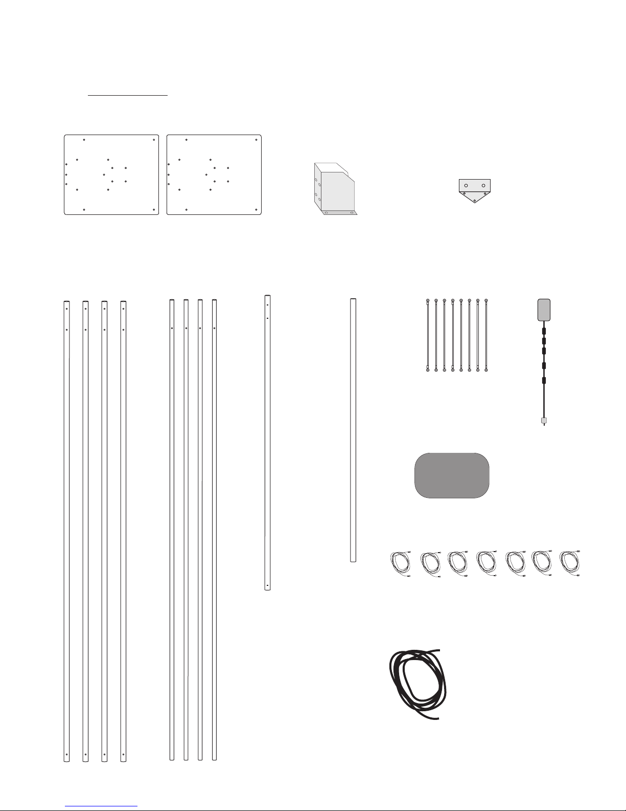
In the box
2 mounting plates 1 mounting bracket
4 x 1-1/4”
element arms
4 x 1”
element arms
1 feed arm
1 support arm
1 u-bolt bracket
8 insulators
Parts pack
Lots of
Nuts and Bolts
1 matching box
1 roll of element wire for each band
10 12 15 17 20 30 40
1 bundle of
dacron rope
Assembly
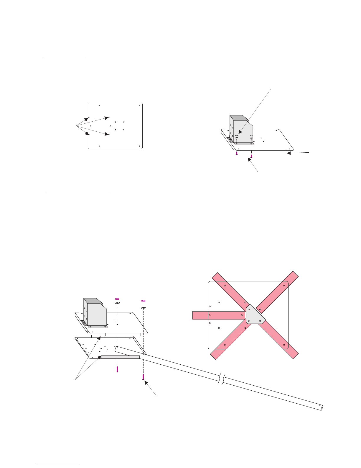
Select one of the two mounting plates. Install the mount bracket onto the plate
using four 10-24 x ½ bolts split washers and nuts. Make sure the nuts are on
the bracket side.
mounting
bracket
holes
Flap down
10-24 x ½
6 places
Support arms
Select one of the four larger (1-1/4” ) element arms. Install the arm between the two plates
using two 10-24 x 1-3/4 inch bolts, split washer and nuts. If you Wish to use the top support
arm, now is when you need to install the u-bolt bracket on the top plate using the same bolts
that hold the arms in and the plates together. Pick any 3 of the 4 holes used to mount the
end of the element tubes. Snug the nuts but do not tighten. If you do not do this now, you
can still do it later, but you will have to remove three of the bolts that hold the element tubes
in the bracket.
Install the remaining three and the shorter feed tube (has mount holes) in the same manner.
Flanges come together
to form an enclosure
Top side of
bracket
10-24 x 1-3/4
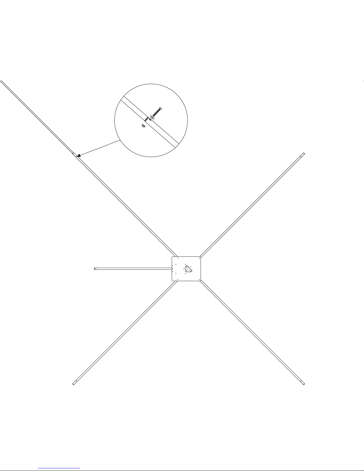
Install the smaller one inch tubes into the larger tubes. Align the holes and
install the 1/4-20 bolt, washer and nylon lock nut as shown.
4 places
 Loading...