

MFJ-1835
10,12,15,17,20 Meter
Cobweb Antenna
Instruction Manual
Caution: Read All Instructions Before Assembling and
Using This Product!
MFJ
300 Industrial Park Road
Starkville, MS, 39759 USA
Tel: 662-323-5869 Fax: 662-323-6551

Introduction: The MFJ-1835 is a compact five-band loop array especially
designed for limited-space installations. Using horizontal polarization, it packs a
3-4 dB gain advantage over ground-independent verticals plus superior immunity
to local noise and RFI. In addition, MFJ’s highly efficient Spider-Match® network
and adjustable tuning tabs guarantee low minimum-SWR on every band. The
MFJ-1835 only measures 9-feet on a side, yet it features a full half-wave element
on every band for no-compromise DX performance -- even when running QRP!
The MFJ-1835 is solidly constructed to take on extreme weather. With sky-gray
fiberglass spreaders and stranded-wire elements, it blends in with any backdrop.
Best of all, it’s omni-directional, so you can omit the rotor and mount it high in the
air using standard low-cost TV-antenna hardware.
Parts List: Before starting assembly, please check the package contents against
the parts list below to ensure all items have been included.
[ ] 2 8" x 8" Aluminum Mounting Plate (737-1835)
[ ] 4 72" Fiberglass Element Support Tube (811-1835-1)
[ ] 1 43" Fiberglass Feed Tube (811-1835-2)
[ ] 1 50-Ohm to 12.5 Ohm Match Box (10-1835-1)
[ ] 1 Mast-Mounting Bracket (735-1835)
[ ] 5 Element End-insulators, 12" x .5" (737-0115)
[ ] 2 Rolls, 10-Meter Element Wire (13-1835-10)
[ ] 2 Rolls, 12-Meter Element Wire (13-1835-12)
[ ] 2 Rolls, 15-Meter Element Wire (13-1835-15)
[ ] 2 Rolls, 17-Meter Element Wire (13-1835-17)
[ ] 2 Rolls, 20-Meter Element Wire (13-1835-20)
[ ] 1 Parts Pack (17-1835-1)
Parts Pack Contents:
[ ] 31 6-32 x 1" screw (656-1000S)
[ ] 14 6-32 x 3/8" screw (656-0375S)
[ ] 47 6-32 Kep Nut (705-0632S-K)
[ ] 21 #6 Flat Washer (561116)
[ ] 2 U-Bolt Assembly (758-9199)
[ ] 5 Cable Tie (745-2158B)
[ ] 10 Tuning adjustment strips (737-1615)
If any components are missing or damaged, refer to the warrantee for
replacement instructions.
Preparation and Site Safety: The MFJ-1835 is lightweight, but a second pair of
hands will always ensure greater safety during assembly and installation. Install
fiberglass spreaders on a flat level surface (driveway, garage floor, etc.) and
complete the assembly using a 5-6 foot temporary mast or pole. The mast will
allow you to string and tension wire element at eye level. Always wear safety
glasses when working with spreaders, and keep the assembly area clear of
people, pets, clutter and debris. Never assemble or install any antenna near
power lines or residential entrance cables!
Important Warning: This antenna is an electrical conductor and, if it comes
into contact with power lines, you can be KILLED. Never assemble or
install any antenna near power lines!
Tools: 7/16" and 5/16" nut drivers, #2 phillips-head screwdriver, diagonal cutters.
Assembly Instructions:
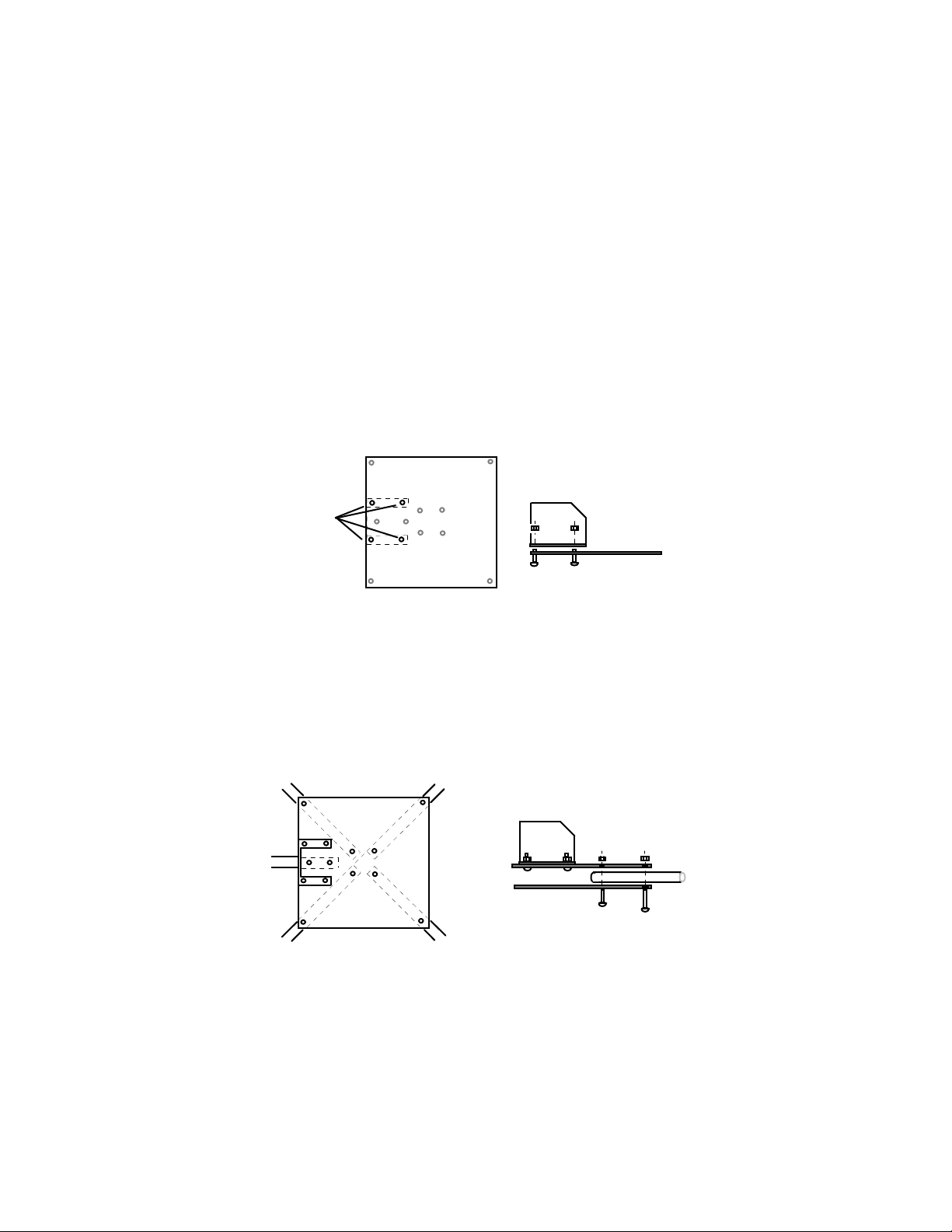
[ ] Locate one of the 8" x 8" aluminum mounting plates and install the mastmount bracket using four (4) 3/8" screws and nuts. Insert screws so the nuts
install on the mast-mount side of the plate. This is the side that will be oriented
toward the ground during final assembly and installation.
Mounting Plate
Mounting
Bracket
Holes
[ ] Locate the second mounting plate and position it so all mounting holes align
with the first plate.
[ ] Install one of the fiberglass support arms as shown, inserting it between the
two plates and securing it with two (2) 1" screws and nuts. Insert screws so the
nuts install on the mounting bracket side of the plate. Finger-tighten for now –
they will be tightened later.
Mounting Plate
Install Tubes Between
the Two Mounting Plates
[ ] Install the remaining three spreader arms in the same manner.
[ ] Locate the matching-network support arm. Before installing, observe the
tube's mounting hole pattern closely. One set of holes will be closer to the end of
the tube than the set at the opposite end. Install using the pair of holes closest to
the end using two (2) 1" screws and nuts.

[ ] Tighten down all of the 6-32 arm-mounting hardware at this time. Also, check
the mounting bracket screws.
[ ] Before continuing with assembly, flip the spreader frame over and mount it on
a temporary mast (5-6 feet). Install the two U-bolt assemblies in the mast mount
and secure the temporary mast. The U-bolts accept tube diameters up to 1-3/4".
[ ] Locate the match box and install it as shown, using the mounting hole closest
to the tip of the feed tube arm (the other hole isn’t used). Secure with a 6-32 nut.
Female UHF
In-Line Connector
Mounting Plates
Mast Mount
Bracket
U-Bolts
Mast
Match Box
Mounting Stud
Hole
Not Used
Balun
Ferrites
Feed Tube
Tie-Wraps
[ ] Use three nylon tie-wraps to secure the coax pigtail to the support tube. The
two remaining tie-wraps may be used later to secure your coax to the feed tube.
[ ] Install flat washers on four (4) 1-inch screws and insert them at the four 10meter spreader locations (holes nearest the center of the antenna). Insert screws
from the top down and thread a nut onto each one (do not tighten).
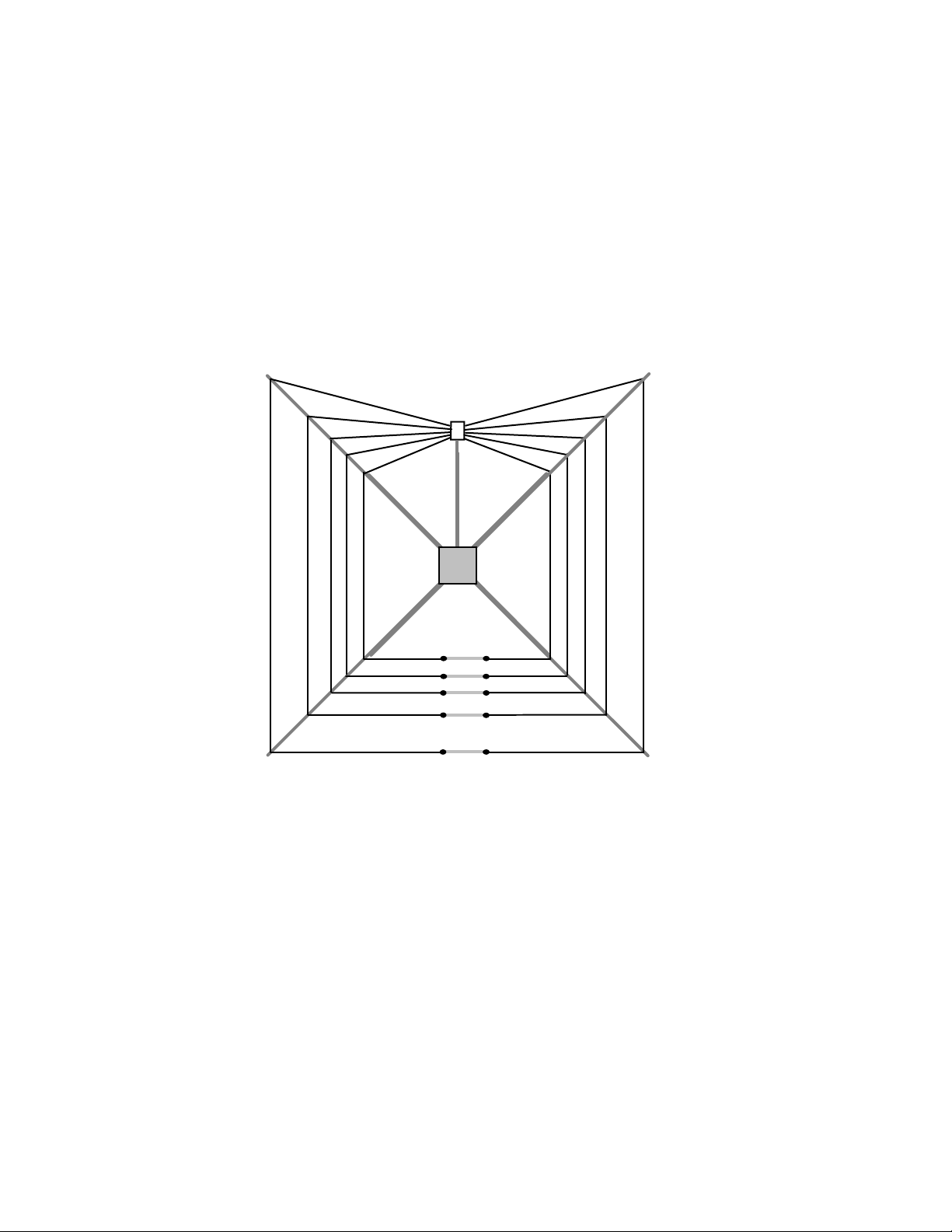
[ ] Connect a 10-meter element wire to one of the matchbox feed screws and
temporarily start a nut over the ring lug to prevent it from slipping off.
String wire from feedpoint
to insulator
>
Pass wire
Feedpoint
under washer
Insulator
Do not tighten nut
Secure to end hole
Insulator
>
[ ] Route the element wire around two adjacent spreaders, catching it under the
flat washers. Do not tighten the screws -- the wire should remain free to slide
back and forth.
[ ] Connect a plastic insulator to the opposite end of the 10-meter wire using a
3/8" screw. Install it in the mounting hole at the end and allow it to hang down.
[ ] In similar fashion, install the other 10-meter wire, connecting the ring lug to
to confirm that each leg is straight
the match box and routing the wire around to the opposite side of the frame.
[ ] At the far end, connect the second wire to the opposite end of the insulator
using the end-hole. Don’t be concerned if the element wire sags. You'll adjust it
later after all of the wires are installed.
[ ] Install the 12-meter loop using the same procedure outlined above.
[ ] Install the 15-meter loop.
[ ] Install the 17-meter loop.
[ ] Install the 20-meter loop.
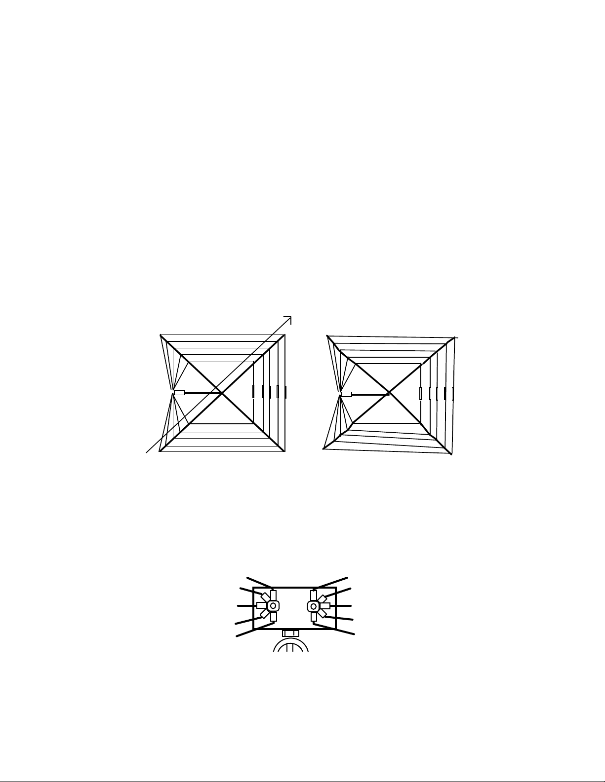
[ ] With all five element wires installed, reduce wire sag by relocating the rig lugs
(as needed) to other mounting holes in the insulators. Do not tension the wires so
tightly that they distort the spreaders or pull the frame out of square. The
objective is to equalize tension and minimize (but not eliminate) sag. Sight down
each support tube to ensure it is straight and 90-degree from the adjacent tubes.
Good
Not Good
Sight down the length of the frame
[ ] Once satisfied with wire tensioning, tighten all spreader screws to secure
each wire in place. Also, tighten the element nuts on the matchbox, fanning out
the ring lugs as needed to ensure flat metal-to-metal contact between each
eyelet. Check all other hardware to confirm everything is secure.
Fan leads so lugs make
full surface-to-surface
contact
Initial Setup: The antenna should be mounted at least 6 feet above ground for
the initial tune-up (higher if practical). If available, use a handheld antenna
analyzer -- it will make tuning a lot faster and safer. Also, when checking SWR,
back away from the elements -- especially in the area surrounding the end
insulators. If you get too close, you could detune them with your body. When
using a transmitter and SWR bridge to check SWR, apply the minimum amount
of power needed to calibrate the bridge and do not make physical contact with
energized elements!
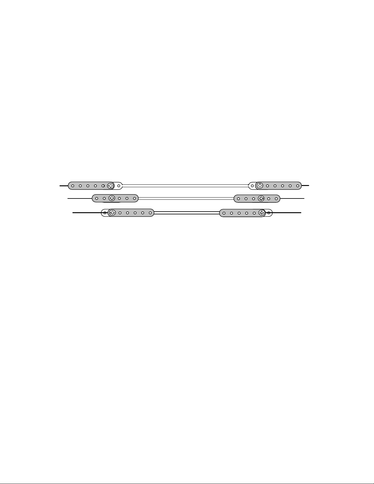
Tuning Procedure: The element wires are pre-cut to resonate at or slightly
above the high-frequency edge of each band. The trim-tab tuning strips are
installed on the insulators to move the minimum-SWR frequency down toward
your favorite band segments without disrupting wire tensioning on the frame. To
lower frequency, position the tabs to electrically extend the element length. Start
with the 20-meter element and work your way in toward the 10-meter element.
Highest in Frequency
Middle Range
Lowest in Frequency
If minimum SWR occurs where you want to it without installing tabs, omit them. If
the tabs fail to pull the frequency low enough, swing one tab down so the end
hole is clear of the insulator and add a short length of wire using a 6-32 screw.
Bandwidth: The 2:1 bandwidth for a half-wave loop is normally much narrower
than it is for a straight-line half-wave dipole, so tune carefully. Also, when
adjusting the antenna close to ground, you may fail to get a deep SWR dip on
one or more of the bands. In this event, tune for the best dip you can get at your
target frequency. The minimum SWR will drop substantially once the antenna is
repositioned at a higher location. After you've installed the antenna at its final
location, always double-check to ensure the lowest SWR points remain where
you want them. New surroundings may cause one or more points to shift. Take
the time to re-adjust -- it’s time well invested.
Antenna Tuners: You may use the MFJ-1835 in conjunction with a tuner to
achieve full-band low-SWR coverage on the wider bands (20, 15, and 10
meters). A tuner will also prove helpful if the elements accumulate ice, snow, or
heavy rain (precipitation loading normally lower resonant frequency). However,
don't use your tuner to compensate for mistuned elements! Perform a careful
tune-up under dry conditions at the time of installation to ensure the best overall
performance.
Antenna Mounting: The MFJ-1835 performs best when raised 20-feet or more
above ground and positioned well away from nearby wiring, metal surfaces, and
large conductive objects. Use any mast diameter between 1-1/4" and 1-3/4" OD,

but the larger diameter is recommended for taller masts. Also, avoid installing
guy wires in close proximity to the elements. Finally, never install where humans
or animals can come in contact with the elements. Be especially attentive to
safety when conducting portable operations in public areas!
Important Warning: Contact with energized element wires can (and will)
cause severe RF burns or even death! Never install the MFJ-1835 where
humans or pets could make accidental contact.
Coaxial Feedline: For best results, use new uncontaminated 50-ohm coax and
avoid making splices that could take on water and cause contamination. The
MFJ-1835 is light in weight and not designed for high power operation, so any
premium grade RG-8X (or Mini-8) should work well (RG-58 okay for short runs).
Larger cables such as RG-8 or 9914 have lower loss, but will add extra weight to
your installation. With lighter cable, you can safely mount the antenna higher in
the air which is normally more beneficial.
Antenna Grounding: Always install a Safety Ground to protect your property
and your equipment from near-by lightning strikes. Connect the base of the
support mast to a suitable ground rod installation using one or more runs of #10
solid aluminum ground wire. Also, always install a barrel connector or junction
box where the cable enters your building and unhook it at the first sign of
threatening weather. Lightning arrestors may provide some protection from
nearby strikes, but a complete disconnect is your only real protection against a
very close or direct hit!
Theory of Operation: The MFJ-1835 consists of five concentrically arranged
1/2-wave horizontal loops mounted on a fiberglass X-frame. The footprint is
square, with all five elements fed in parallel through a reactance-compensated
broadband autotransformer. The radiation pattern is virtually omni-directional (±
1.5 dB). A sleeve-style ferrite balun is installed at the feedpont to choke off
unwanted common-mode radiation. The balun also reduces receiver-noise
pickup and spurious RFI signals generated by consumer devices. Weighing just
over eight pounds, the MFJ-1835 installs easily on virtually any portable or
permanent mast from 1-1/4” to 1-3/4” OD.
Specifications:
Minimum SWR: 1.1:1 or lower all bands, measured at 20' AGL
Modeled Gain: 4.7 dBi at 20-feet AGL on 14.2 MHz with 37º TOA.
Modeled Pattern: Omni-directional, ±1.5 dB, max. gain on axis with feedpoint.
Power Handling: 300-W pep SSB/CW recommended, never exceed 600-W
Dimensions: 9’ x 9’ per side, 12' diagonally
Weight: 8.2 pounds
Mast Size 1-3/4" OD maximum

Warrantee
If manufactured by MFJ Enterprises, Inc. and purchased from an authorized dealer or directly
from MFJ, we warrant to the original owner that this product shall be free from defects in material
and workmanship for a period of 12 months from date-of-purchase provided the following terms
and conditions are satisfied:
1. The purchaser must retain a dated proof-of-purchase (bill of sale, cancelled check, credit card
or money order receipt, etc.) describing the product so as to establish the validity of the warranty
claim. In addition, the original copy or machine reproduction of such proof shall be provided to
MFJ at the time of warranty service. MFJ shall have the discretion to deny warranty service
without dated proof-of-purchase. Any evidence of alteration, erasure, or forgery shall be
cause to void any and all warranty terms immediately.
2. MFJ agrees to repair or replace, at its option and without charge to the original
owner, any defective product under warranty, provided the product is returned postage prepaid to
MFJ Enterprises, Inc. with a personal check, cashiers check, or money order in the amount of
$7.00 to cover postage and handling.
3. MFJ Enterprises, Inc. will supply any replacement parts free of charge for any MFJ product
under warranty upon request. A dated proof-of-purchase and a $5.00 personal check, cashiers
check, or money order must be provided to cover postage and handling for parts and materials.
4. This warranty shall not be voided for owners who attempt to repair defective units. Technical
consultation is available by calling (662) 323-5869.
5. This warranty does not apply to kits sold by or manufactured by MFJ Enterprises, Inc. (once
assembly begins, the owner becomes the manufacturer).
6. Wired and tested PC board products are covered by this warranty provided only the wired and
tested PC board product is returned. Wired and tested PC boards installed in the owner’s own
cabinet or connected to switches, jacks, or cables, etc. and sent to MFJ Enterprises, Inc. will be
returned at the owner’s expense un-repaired.
7. Under no circumstances shall MFJ Enterprises, Inc. be liable for consequential damages to
persons or property by the use of any MFJ products.
8. Out-of-warranty Service: MFJ Enterprises, Inc. will repair any out-of-warranty product provided
the unit is shipped prepaid. All repaired units will be shipped COD to the owner. Repair charges
will be added to the COD fee unless other arrangements are made.
9. This warranty is given in lieu of any other warranty expressed or implied.
10. MFJ Enterprises, Inc. reserves the right to make changes or improvements in the design or
manufacture of its products without incurring any obligation to install such changes upon products
previously manufactured.
11. All MFJ products to be serviced in-warranty or out-of-warranty should be addressed to MFJ
Enterprises, Inc., 300 Industrial Park Road, Starkville, Mississippi 39759, USA and must be
accompanied by a letter describing the problem in detail along with a copy of a dated proof-ofpurchase.
12. This warranty conveys specific rights, and you may also be entitled to other rights which may
vary from state to state.
 Loading...