

Page 1

INTRODUCTION
Thank you for purchasing the MFJ portable antenna. Your new portable antenna uses base
loaded telescopic whips, and is specifically designed for the Yaesu FT-817 radio. For lower
frequencies more inductance is needed to establish resonance, for the higher bands, progressively
less inductance is needed. On the MFJ-1899T model this is conveniently achieved by providing a
series of tap positions. Also, making small adjustments to the telescopic section fine-tunes both
models. Though the FT-817 has a VSWR meter, this adjustment is easy to carry out. However,
do not touch the antenna while transmitting. To generate carrier you will need to temporarily
switch to AM or FM. You could of course whistle into the mic on SSB, but whatever method
you use, please check to see if the channel is clear and that you are not going to cause interference
to your fellow hams.
HOW TO GET THE BEST FROM YOUR ANTENNA
With fixed HF vertical antennas the efficiency is greatly improved when using some form of
ground plane. VHF and UHF handheld radios and their associated whips work well allowing you
to wander around the countryside, or down the street, enjoying ham radio communications.
However, stop and think how this antenna actually works. Consider a simple quarter wave
vertical on a 2m VHF handheld. Like any quarter wave vertical it needs a ground plane, in this
case around 19” in length. This is easily provided by the copper on the radio’s circuit board and
aided by the operator’s hand capacity. Therefore, when operating VHF or UHF, do not consider
the missing quarter wave “counterpoise”. There is enough stray capacity and inductance to take
care of this.
However, on HF it is completely different. There is no way that the radio can offer a sufficient
ground plane for an HF vertical antenna to work. In fact, you can easily prove the point for
yourself. Attach a resonant antenna, then switch to the appropriate band and listen to a signal.
Then, grasp the radio firmly with both hands and hear how the signal rises. Place the radio on a
metal surface such as an office filing cabinet and hear the same effect. This shows the
importance of a ground plane.
It is crucial to provide the missing quarter wave ground plane in order to achieve efficient
operation. (Think of the FT-817 as the center of a dipole, the whip as one half of the dipole and
the quarter wave wire as the other half) To provide the missing length of wire, you need to attach
a length of flex to the earth terminal on the FT-817 and run it along the ground or throw it out a
window. Length is not absolutely critical but you should aim for the lengths mentioned on the
next page. For the low frequency bands, you could save yourself some length by adding an
inductor in the wire, but you will have to experiment with values and lengths. To improve signals
even more, carry a short copper stake to go into the ground and attach this to your radio and the
ground plane. The gauge of the flex is not important and it does not matter whether you use bare
copper or plastic covered flex.
The FT-817 is so much more than just a fun radio and with your new antenna, it offers the
ultimate in portability. To get the best out of the transceiver, adherence to the above information
is very important. You will then find yourself having as many DX QSOs as you desire.
1
Page 2
PORTABLE TELESCOPICS FOR YAESU FT-817
MFJ-1806T through MFJ1880T
Length of telescopic is bottom end of each band, with ground plane wire fixed
to earth connection of radio.
LENGTH OF GROUND PLANE WIRE
2m, 70cm, and dual band antennas do not need a ground wire.
MFJ-1806T 6m.............109.22cm (3’ -7”)
MFJ-1810T 10m...........195.58cm (6’ -5”)
MFJ-1812T 12m...........220.98cm (7’ -3”)
MFJ-1815T 15m...........261.62cm (8’ -7”)
MFJ-1817T 17m...........304.8cm (10’ -0”)
MFJ-1820T 20m...........391.16cm (12’ -10”)
MFJ-1830T 30m...........548.64cm (18’ -0”)
MFJ-1840T 40m...........784.86cm (25’ -9”)
MFJ-1880T 80m...........1569.72cm (51’ -6”)
Ground plane lengths given for lowest frequency in each band. Longer lengths
of wire are needed the lower the band.
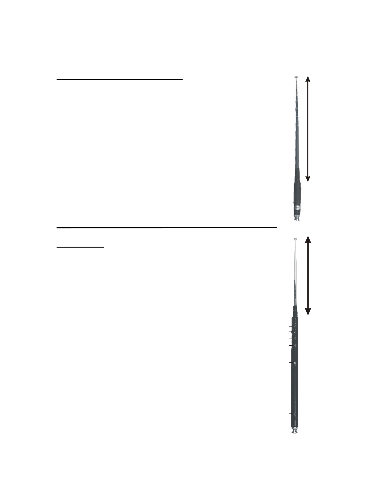
APPROXIMATELY 48” ADJUST FOR LOW VSWR
MFJ- 1899T
Lengths of telescopics are for lowest frequency in band and with ground plane
wire connected to radio. The best length for the ground plane wire is less than
1/4 wave. 180 ÷ freq (in MHz) = length in feet. The telescopic can be
adjusted for best VSWR.
LENGTH OF TELESCOPIC
80m (no jumper lead connected) approx. 121.92cm (48”)
40m No.1 connected to No.2 approx. 121.92cm (48”)
30m No.1 connected to No.2 approx. 45.72cm (18”)
20m No.1 connected to No.3 approx. 121.92cm(48”)
17m No.1 connected to No.3 approx. 76.2cm (30”)
15m No.1 connected to No.4 approx. 121.92cm (48”)
12m No.1 connected to No.4 approx. 93.98cm (37”)
10m No.1 connected to No.5 approx. 121.92cm(48”)
6m No.1 connected to No.6 approx. 101.6cm (40”)
4m No.1 connected to No.6 approx. 55.88cm (22”)
Note: With No.1 connected to No.6, the antenna will also make a reasonable
5/8 wave on 2m and air band.
Telescopic length on 2m approx. 114.3cm (45”)
Telescopic length of Air band approx. 127cm (50”)
LENGTH OF TELESCOPIC
6
5
4
3
2
1
2
Page 3

LIMITED 12-MONTH WARRANTY
MFJ Enterprises, Inc. warrants to the original owner of this product, if manufactured by MFJ
Enterprises, Inc. and purchased from an authorized dealer or directly from MFJ Enterprises, Inc.
to be free from defects in material and workmanship for a period of 12 months from date of
purchase provided the following terms of this warranty are satisfied.
1. The purchaser must retain the dated proof-of-purchase (bill of sale, canceled check, credit
card or money order receipt, etc.) describing the product to establish the validity of the
warranty claim and submit the original or machine reproduction of such proof of purchase
to MFJ Enterprises, Inc. at the time of warranty service. MFJ Enterprises, Inc. shall have
the discretion to deny warranty without dated proof-of-purchase. Any evidence of
alteration, erasure, or forgery shall be cause to void any and all warranty terms
immediately.
2. MFJ Enterprises, Inc. agrees to repair or replace at MFJ's option without charge to the
original owner any defective product under warrantee provided the product is returned
postage prepaid to MFJ Enterprises, Inc. with a personal check, cashiers check, or money
order for $7.00 covering postage and handling.
3. This warranty is NOT void for owners who attempt to repair defective units. Technical
consultation is available by calling the Service Department at 662-323-0549 or the MFJ
Factory at 662-323-5869.
4. This warranty does not apply to kits sold by or manufactured by MFJ Enterprises, Inc.
5. Wired and tested PC board products are covered by this warranty provided only the wired
and tested PC board product is returned. Wired and tested PC boards installed in the
owner's cabinet or connected to switches, jacks, or cables, etc. sent to MFJ Enterprises,
Inc. will be returned at the owner's expense unrepaired.
6. Under no circumstances is MFJ Enterprises, Inc. liable for consequential damages to
person or property by the use of any MFJ products.
7. Out-of-Warranty Service: MFJ Enterprises, Inc. will repair any out-of-warranty product
provided the unit is shipped prepaid. All repaired units will be shipped COD to the owner.
Repair charges will be added to the COD fee unless other arrangements are made.
8. This warranty is given in lieu of any other warranty expressed or implied.
9. MFJ Enterprises, Inc. reserves the right to make changes or improvements in design or
manufacture without incurring any obligation to install such changes upon any of the
products previously manufactured.
10. All MFJ products to be serviced in-warranty or out-of-warranty should be addressed to:
MFJ Enterprises, Inc.,
300 Industrial Park Road
Starkville, Mississippi 39759 USA
and must be accompanied by a letter describing the problem in detail along with a copy of
your dated proof-of-purchase.
11. This warranty gives you specific rights, and you may also have other rights which vary
from state to state.
3
 Loading...