

WARC Band Portable Antenna
Model MFJ-1795W
VERSION 1A
INSTRUCTION MANUAL
CAUTION: Read All Instructions Before Operating Equipment
MFJ ENTERPRISES, INC.
300 Industrial Park Road
Starkville, MS 39759 USA
Tel: 662-323-5869 Fax: 662-323-6551
COPYRIGHT 2006 MFJ ENTERPRISES, INC.
C
MFJ-1795W Vertical Antenna Instruction Manual
60 Meter
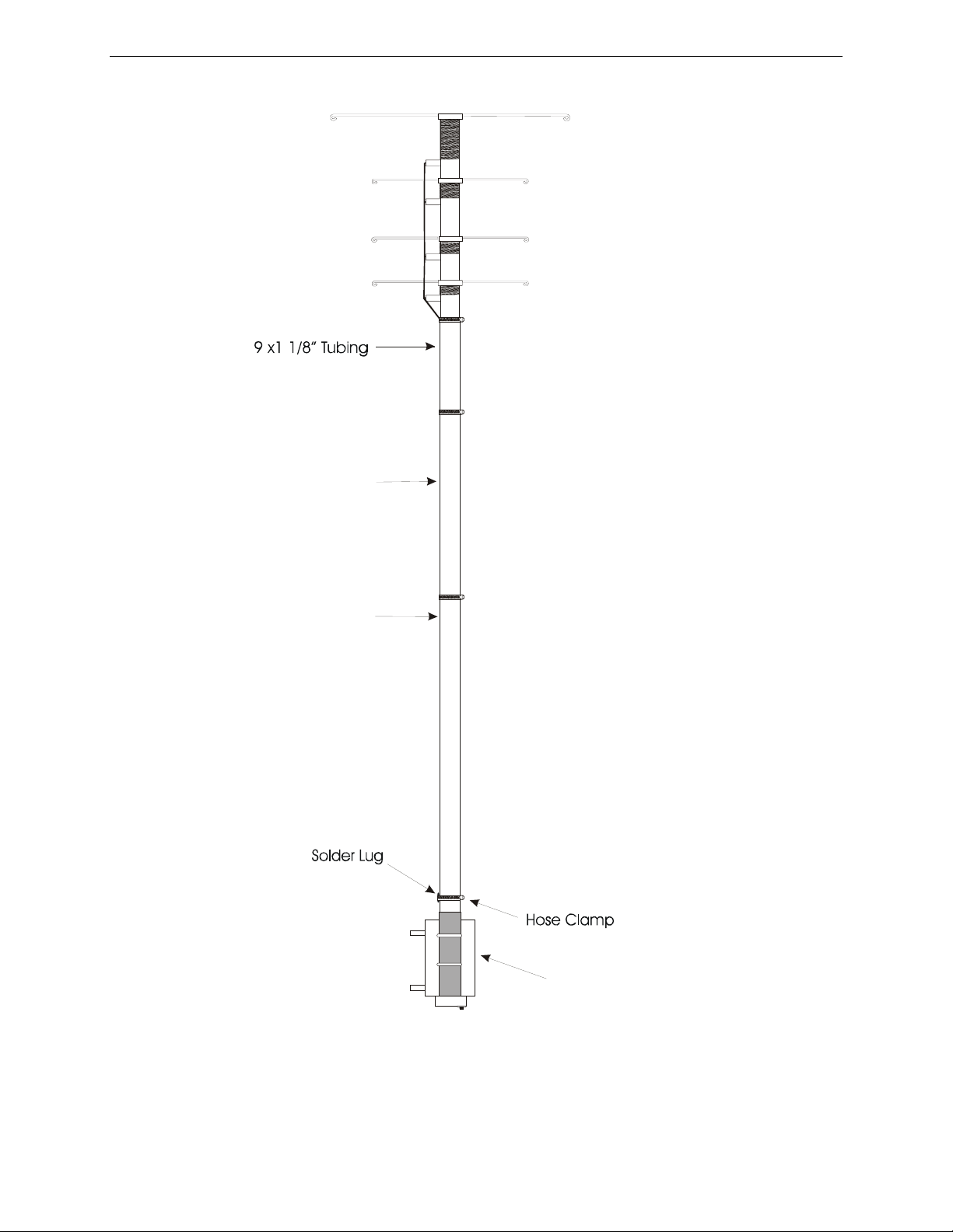
Capacitance Spokes (8)
& Loading Coil
30 Meter (4)
17 Meter (4)
12 Meter (4)
30 x 1” Tubing
1” x 30”
MFJ-1795W
WARC Band
Vertical Antenna
Always
Follow
Assembly
Instructions!!
5’ x1 1/8” Tubing
Mount
Mounting Bracket
Note: This drawing is not to scale
WARC Bands Vertical Antenna
1

MFJ-1795W Vertical Antenna Instruction Manual
INTRODUCTION
The MFJ-1795W HF antenna was designed to provide portable or permanent WARC Band
operation from restricted locations. When combined with the MFJ Ground-Coupled™ Portable
Antenna Base or other suitable grounding system, such as radial system, the result is a small
vertical antenna under 10 feet in height.
The reduction in size is accomplished by adding separate loading coils and capacitance hats for
each band at the top of the antenna. The efficient end loading coils are wound on fiberglass
forms. The high quality materials and construction of the HF loading system allows a maximum
power rating of 1500 watts SSB PEP on 60, 30, 17 and 12 meters.
The power rating of this antenna varies from band to band. The PEP ratings are primarily
determined by the voltage breakdown of the components, while the CW ratings are generally
determined by the components heating.
The following chart lists the power rating and the 2:1 VSWR bandwidth of this antenna:
Band (Meters) Power (Watts) Bandwidth (KHz)
CW SSB RTTY
60m 700 1500 500 100
30m 1250 1500 750 300
17m 1250 1500 1000 1000
12m 1250 1500 750 2000
The weight and wind load of this antenna are 10 pounds and approximately two square feet
respectively.
WARNING: Improper installation and assembly can be hazardous! Read
these instructions thoroughly before attempting to assemble, install, or
operate this product! High power transmitting devices produce voltages that
can cause severe burns or other injuries.
CHOOSING A LOCATION FOR THE ANTENNA
The best performance on receiving and transmitting will be obtained by mounting the antenna in
a clear location above or away from buildings, towers, feed-lines, utility wires, and other
antennas. While your own ingenuity and particular circumstances will determine the final
mounting method, we will pass along a few ideas for both permanent and portable installation.
WARNING: Always mount this antenna so that it is out of the reach of adults as well as
children. The capacitance elements can cause injury and or severe RF burns.
2

MFJ-1795W Vertical Antenna Instruction Manual
• Never place this antenna in a location that will permit people to encounter the loading
spokes or any other part of the antenna.
• Never place this antenna where a mechanical failure might allow the antenna to contact
power lines or other utility wires.
• Always ground the feed-line at the point where it enters a building to a good earth ground
for lightning protection.
• Follow the guidelines for antenna installations as recommended by the US consumer
product safety commission.
ANTENNA HEIGHT
The height of the radiating element is adjustable from 5 to 8 feet. Maximum radiation will be
obtained by setting the height of the radiating element at 8 feet. Some installations may require
the antenna height to be reduced. An example may be the installation of the antenna inside a
backyard fence for concealment. Height adjustment will be discussed in the assembly section of
this manual.
INSTALLATION
The MFJ-1795W was designed as a low profile, portable antenna. When combined with the MFJ
Ground-Coupled™ Portable Antenna Base the antenna will provide permanent or portable
communications. This is an ideal antenna for restricted locations. However, the antenna
installation MUST be protected with non-metallic fencing to provide personal safety and to
prevent antenna damage. The antenna can be installed using the supplied mounting bracket and
a suitable ground radial system.
IMPORTANT: A suitable ground plane must be installed with this antenna.
PORTABLE SETUP
The antenna may be disassembled to the extent necessary for transporting to a temporary
location. Before the antenna is disassembled, some type of marks should be placed on the mast
of the antenna to ensure it will be the same height as before. Some retuning may be required
after moving the antenna.
WARNING: If the antenna falls it will be damaged and may cause serious injury.
Whatever type of installation you choose, remember that the antenna should be installed
where it can never be contacted by people or animals.
TOOLS AND TIME REQUIRED FOR ASSEMBLY
3

MFJ-1795W Vertical Antenna Instruction Manual
The estimated assembly time for this antenna is 1 hour. Antenna assembly requires the following
hand tools:
[ ] soldering iron and solder
[ ] 5/16" nut driver (or 1/4" flathead screwdriver)
[ ] 7/16" open end wrench
[ ] Heavy wire cutters for trimming capacitance spokes
[ ] small pliers
[ ] #1 phillips screwdriver
[ ] #2 phillips screwdriver
[ ] suitable eye protection
In addition, you will need two stable supports at least 30" tall (i.e. saw horses or trash cans) and
a short (6 to 8 feet) temporary mast (1 to 1-1/2 inches outside diameter) for temporary mounting
during tuning.
MFJ-1795W PARTS LIST
As you unpack your antenna you should find the parts in the following list.
[ ] two (2) bundles of wire capacitance spokes eight (8) 21” spokes, and 14 36” spokes, and two
(2) spare 21” spokes.
[ ] 5' radiator 1 1/8"
[ ] 30”x 1” radiator
[ ] 9”x 1 1/8” radiator
[ ] loading coil assembly
[ ] base mounting bracket
[ ] hollow fiberglass rod insulator
[ ] One Hardware Bag containing
[ ] 4 1.5” hose clamps
[ ] bag of short 6-32 stainless screws
[ ] bag of 6-32 stainless kep nuts
[ ] bag of 1/8" plastic spoke caps
[ ] 4 U-bolts with hardware
[ ] two plastic tie wraps
[ ] 2 solder lugs
For installation you will need some additional items not supplied with the antenna installation
kit.
[ ] Quality low-loss 50-Ohm coax with a PL-259 to go from the antenna to the transmitter.
[ ] Either a SWR meter or Analyzer (MFJ-259B, 269)
SAFETY PRECAUTIONS:
4
 Loading...