

Page 1

MFJ Super Hi-Q Loop Antenna Instruction Manual
MFJ
CAUTION: Do Not Attempt Operation Of This Unit Before Reading All Instructions
The MFJ "Super Hi-Q Loop" is the best performing and most convenient small space antenna available
to amateurs today. The MFJ-1786 covers 10 MHz to 30 MHz. The MFJ-1788 covers 7 MHz to 21
MHz. The antenna is only 36 inches in diameter and features an indoor semi-automatic tuning unit with
a built-in cross needle wattmeter. All tuning and control voltages are coupled to the antenna through
the coaxial feedline for simple, neat, one wire installation.
The loop antenna element is constructed from thick walled aluminum pipe. Every current carrying
joint is welded to eliminate high resistance pressure contacts that reduce efficiency. The loop element
is tuned with a low-resistance, high current, variable capacitor. The outdoor electrical and mechanical
components are protected by an attractive weather resistant molded cover.
WARNING! Never mount this, or any other antenna near power lines or utility wires! Any
materials: ladders, ropes, or feedlines, that contact power lines can conduct
voltages that kill. Never trust insulation to protect you. Stay away from all power
lines.
Super Hi-Q Loop
Antenna
THEORY OF OPERATION
When resistive losses in a small loop antenna are kept low, a small loop antenna will transmit nearly as
well as a full size dipole. MFJ was able to make this small loop antenna radiate nearly as well as a full
size dipole by paying special attention to the electrical and mechanical construction of this antenna.
Because radio frequency currents primarily flow near the thin, outer edges of flat conductor loops, flat
conductor loops will have much higher RF losses. To avoid this problem the MFJ "Super Hi-Q Loop"
uses a thick wall, large diameter, round aluminum pipe for the radiating element. This construction
method results in much better performance since the RF losses in the round, large diameter pipe are
many times lower than the losses in a flat conductor.
MFJ forms the large diameter aluminum pipe into a circle on special machines and heli-arc welds all
joints to eliminate resistive pressure connections in the antenna. A specially constructed butterfly
capacitor using arc-welded construction has much lower loss resistance than conventional, less
expensive, pressure contact, air variable capacitors.
The care and expense used in selecting the best materials, not the most convenient materials, has
resulted in an extremely efficient small size antenna. Extensive "on the air" tests have confirmed that
most stations can detect little difference between the signal from the MFJ "Super Hi-Q Loop" and the
signal from a full size dipole at the same height.
1
Page 2
MFJ Super Hi-Q Loop™ Antenna Instruction Manual
PATTERNS, POLARIZATION AND LOCATION
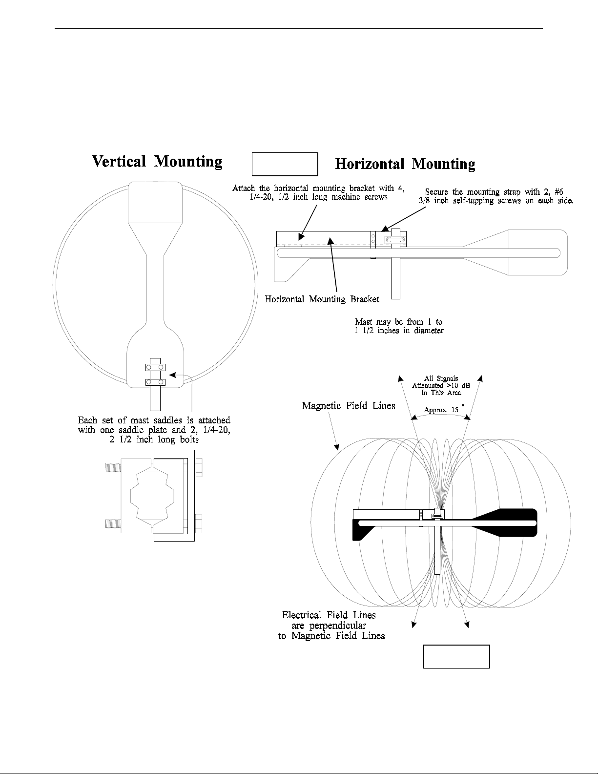
This loop antenna can be mounted to provide either vertical or horizontal polarization. To mount this
antenna for vertical polarization the loop should be mounted standing up. To mount the loop for
horizontal polarization the loop should be mounted so it lays flat.
Figure 1
The radiation pattern of a small loop
antenna is essentially omni-directional with
the exception of two very narrow nulls in
the axis of the loop. If you visualize the
loop as a "wheel", the nulls are in the same
directions that the "wheel's axle" would run.
Figure 2
2
Page 3
MFJ Super Hi-Q Loop Antenna Instruction Manual
Signals will be attenuated more than 10 dB if they arrive within 15 degrees of the axis of the loop.
In general this antenna, like most others, should be mounted as far away from and as high above other
objects as possible. The "null" (or broadside axis) of the loop should be placed in line with the
direction that you do not want to transmit or receive.
feet above ground,
or above a metal roof, the best mounting arrangement will be with the loop
If the loop can not be mounted more than 20
vertical. If the loop is mounted over 20 feet above the ground (or ground plane) a horizontally
mounted loop will probably be the most satisfactory.
NULLING UNWANTED SIGNALS
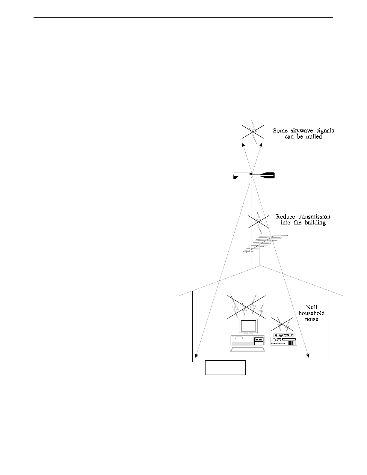
The narrow loop nulls can be used to reduce
interference from undesired directions, if the
unwanted signal is coming from a fixed
direction and wave angle. The narrow null
pattern usually makes tilting the loop a
requirement to null sky wave signals. Because
of the constantly changing angle and direction
of sky wave signals the nulls of the loop are
probably most useful for eliminating ground
wave interference, although they can be
effective on some sky wave signals.
Other examples of using the "null" can be
understood if we consider a loop antenna
located on a roof. By mounting the antenna
horizontally above the middle of the roof the
"null" can be positioned directly below the
antenna (through the building). This mounting
arrangement helps receiving by reducing the
noise pick-up from devices in the building and
helps transmitting because energy is not
coupled into the building's "lossy" structure.
RFI in the building will also be reduced
because the signal transmitted into the building
is weaker.
Figure 3
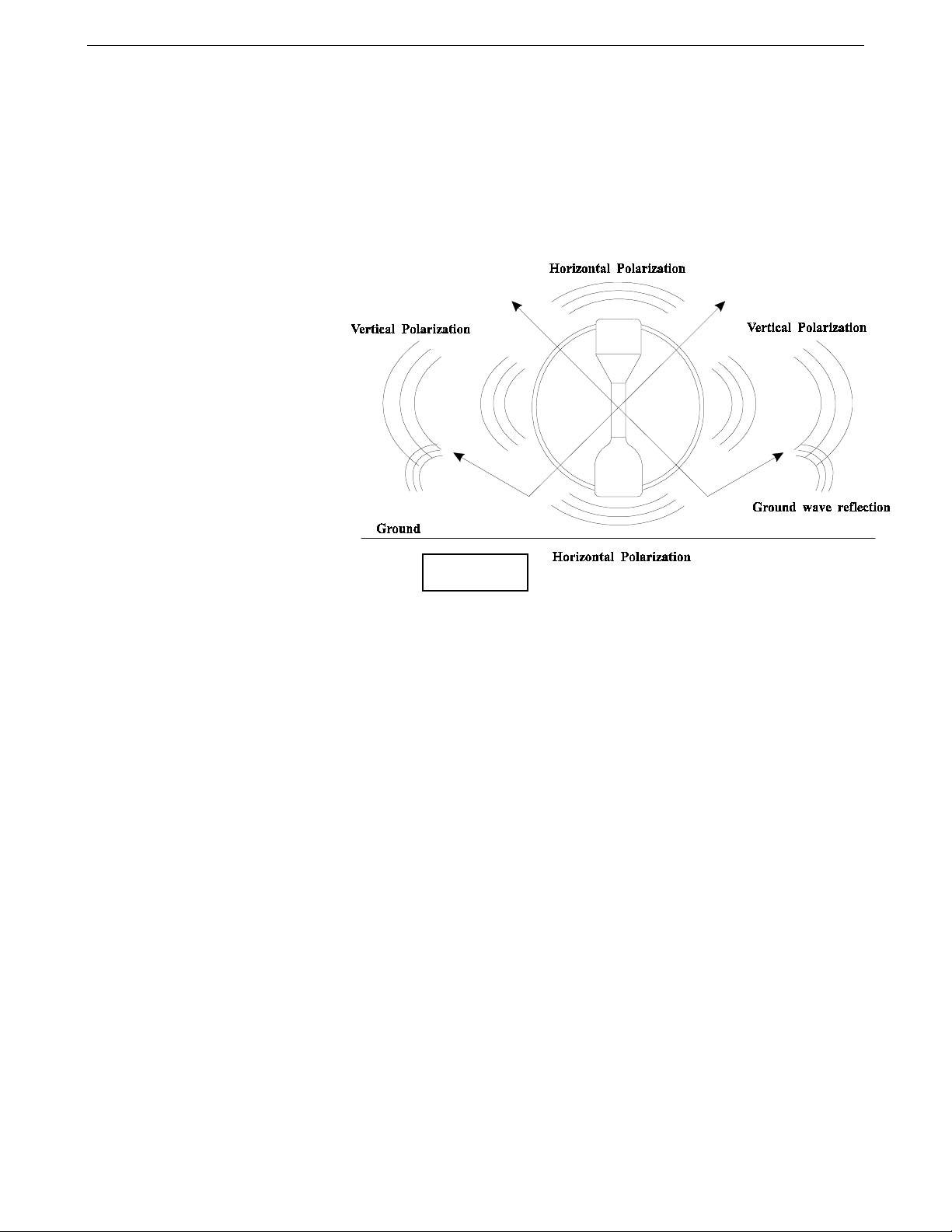
VERTICAL POLARIZATION
When the loop is mounted to provide vertical polarization the pattern is vertically polarized in line with
the loop element. There will still be a large amount of horizontally polarized radiation broadside to the
loop, especially if the ground under the loop is less than perfect or if the loop is mounted some distance
above the ground.
3
Page 4
MFJ Super Hi-Q Loop™ Antenna Instruction Manual
The broadside horizontal radiation that occurs in a small vertical loop is mostly above 10 degree wave
angles and extends straight above the loop and to the opposite 10 degree elevation point.
vertical polarization occurs only in line with the loop
. As you move around the loop towards the
True
sides, the pattern "skews" and eventually becomes completely horizontal broadside to the loop.
Unlike linear verticals,
vertically polarized small loops
also radiate straight up and
down from the antenna. This
high angle radiation can be used
to cover short distances by sky
wave. The high angle horizontal
radiation in a vertically
polarized loop antenna occurs
because the ground below the
loop is either too far away or is
not a good enough RF reflector
to cancel the horizontal
radiation component of the
vertical loop.
Figure 4
This effect can be reduced by laying a screen or grid of wires that extend for at least 20 feet each
direction from the antenna just below a vertically mounted loop antenna, or mounting the loop
vertically over a large metal roof.
HORIZONTAL POLARIZATION
Horizontal mounting of the loop antenna results in an omni-direction, horizontally polarized pattern
that has a null straight up in the air and straight below the center of the antenna. This means that any
ground reflection will tend to cancel the radiation along the horizon, and also at low wave angles
unless the loop is mounted some distance above ground. Mounting a horizontal SMALL loop antenna
just above a good reflecting ground will practically guarantee no useful signal in any direction!
Do not expect the best results if you mount this loop antenna horizontally if it is less than 20
Note:
feet above a metal roof or other ground plane!
Since ground wave signals only propagate well along the earth when they are vertically polarized, a
horizontally polarized loop may not respond to some local noise sources. Like all other antennas, a
small loop is generally a quieter receiving antenna when horizontally polarized. This also means that a
horizontally polarized loop is not a good choice for local ground wave communications. However, it is
an excellent choice for medium to long distance sky wave communications.
4
Page 5

MFJ Super Hi-Q Loop Antenna Instruction Manual
OUTDOOR LOOP INSTALLATION
The MFJ "Super HI-Q Loop" has two mounting clamps that are held in place by four 1/4-20 7/16" hex
head bolts. The mounting clamps accept masts up to 1-1/2" outside diameter.
Before mounting the antenna read the section on "PATTERNS, POLARIZATION AND LOCATION".
The following rules must be followed when mounting the antenna:
1.) The black housing on the loop element has drain holes for moisture. Never seal the drain holes.
2.) The coax connector must always be at the bottom of the antenna when the antenna is mounted
vertically or pointed towards the ground when the antenna is mounted horizontally.
3.) If the loop is mounted
vertically
do not extend the mast more than two inches beyond the
mounting clamps or the tuning and operation of the loop may be compromised.
4.) If the loop is mounted
horizontally
the horizontal bracket must be installed. Use four 1/4-20 1/2
inch machine screws at the base of the bracket. Secure the mounting strap around the antenna
with 2, #6 3/8 inch on each side. The mast saddles can now be attached to the side of the
mounting bracket. Refer to Figure 1.
5.) Always support the coax by securing it to the mast just below the mounting clamps. Never let the
weight of the coax hang on the connector. Some improvement in lightning protection of the loop
electronics can be achieved by coiling and taping the coax into a two turn, one foot diameter, loop
between the antenna and the mast. Be sure this lightning retarding loop is below the plane of the
antenna and at right angles to it.
6.) If you use "coax seal" use it
sparingly
connector and the knurled area of the male coax connector.
. Seal
the area near the top of the loop's female
only
Sealing the bottom gap in the male
coax fittings outer shell, or the gap between the black housing and the connector on the
loop, prevents condensation from draining out of the connectors and the loop housing
.
Note:
The best material used to seal connectors is either GE Dielectric Silicone Compound or a clear
silicone heat sink compound. Use sealing compounds SPARINGLY on the threads of coax
connectors. This is the same type of waterproofing material used by CATV and commercial
antenna installers with good success.
7.) The mast or supporting structure should be galvanized steel or thick walled aluminum mast and at
least 1-1/4" OD. Do not use thin wall aluminum tubing or standard steel electrical conduit to
support the loop. The mast should be supported or guyed as close to the mounting point of the
loop as possible and
Never
more than five feet below the loop. Non-conductive guy lines or guy
lines with insulators installed to break the guy into 13 feet or shorter lengths should be used. This
is especially important within 20 feet of the loop.
5
Page 6

MFJ Super Hi-Q Loop™ Antenna Instruction Manual
8.) The mast should be grounded for lightning protection and electrical safety. The coax feedline
should be dressed down the mast and have it's shield grounded at the point where it enters a
building for lightning protection.
WARNING! Never mount this, or any other antenna near power lines or utility wires! Any
materials: ladders, ropes, or feedlines, that contact power lines can conduct
voltages that kill. Never trust insulation to protect you. Stay away from all power
lines.
This antenna can be used inside a wooden or non-metallic building with some reduction in
performance. Caution must be used when this antenna is used indoors because the antenna generates
strong electromagnetic fields. These fields can induce considerable RF currents into wiring and other
metallic items. A secondary concern is that the effects of RF fields on humans is not yet fully
understood.
WARNING! Never operate this antenna where people are subject to high levels of RF
exposure, especially above 10 watts or above 14 MHz.
Never use this antenna near RF sensitive medical devices such as pacemakers.
Figure 5
6
Page 7

MFJ Super Hi-Q Loop Antenna Instruction Manual
INDOOR CONTROL BOX INSTALLATION
WARNING! Do not install any devices between the control box and the loop antenna! If
anything causes a low DC resistance or short between the center conductor of the
coax and ground the control box or power supply will be damaged.
The control unit of the MFJ "Super Hi-Q Loop" can be located at any position that allows easy access
to the controls of the unit and the transceiver. The coax lines should be good quality 50 ohm lines and
should be kept reasonably short to reduce losses. If you use quality low-loss cable, the exact lengths
used are unimportant and will not effect the operation or SWR of the system. However, if you use
lossy cable adjustment of the control head may be necessary.
If you are using a lossy cable between your antenna and controller and have problem tuning, the easiest
way to correct the problem is to get better quality cable. If changing the cable is impractical,
adjustment of R10 to the minimum may correct the problem. If you still get a needle dip and the motor
does not stop, adjust R10 to the middle setting and try shorting R11.
The power supply used with this unit must not be connected to any other devices while connected to
the loop control box.
CAUTION: The power supply of this unit must not be grounded! If either the positive or
negative leads are grounded the control unit will be damaged! Use only the MFJ1312B, MFJ-1315X or equiv. supplied with this unit!
7
Figure 6
Page 8

MFJ Super Hi-Q Loop™ Antenna Instruction Manual
CONTROL HEAD THEORY AND OPERATION
The MFJ "Super Hi-Q Loop" control head contains a cross needle SWR-WATTMETER that reads
forward and reflected power on high and low power scales. The high power scales are 300 watts
forward and 60 watts reflected, and the low power scales are 30 watts forward and 6 watts reflected.
Power is always read from the top scale with a 0.1 multiplier in low power.
The control head supplies control voltages to the loop antenna through the coaxial feedline. These
voltages are low voltage and low current so that the length of the coaxial line does not affect the
operation of the motor. It is important that the feedline remain water-free and that there are no short
circuits between the center conductor and the shield of the feedline.
The control head also contains the circuits that detect the tuning condition of the antenna. These
circuits are activated only when the AUTO BAND SELECT "UP" or "DOWN" buttons are depressed.
When these switches are "latched" in the presence of constant RF, the loop will tune until the SWR
drops or the end of the tuning range is met. If the SWR minimum is crossed a "beeper" sounds and the
motor voltage is removed. If the end of range is reached without crossing the SWR minimum the
FREQ "UP" or "DOWN" LED will extinguish and the motor will stop. When you release the "latched"
button after the low SWR point is crossed a "MOVE" LED near the "FINE TUNE" buttons will be lit.
The control head also contains circuits that allow the motor to move in slow steps. To optimize the
SWR the FINE TUNE buttons are used. The "MOVE" LED's that indicated which way you needed to
move after using the AUTO BAND SELECT will extinguish after the proper FINE TUNE button is
pressed.
Additionally, there are switches for wattmeter power sensitivity, the meter lamp, and main power offon. There are also two yellow LED's labeled "FREQ" UP and DOWN that monitor the current that the
loop motor (feedline) is drawing. A continuous light indicates that one of the "AUTO BAND
SELECT" switches is on and the motor is running, a flashing LED indicates that a FINE TUNE switch
is on. These LED's should NOT remain lit after the motor reaches a stop. This condition should occur
in less than 40 seconds of fast tuning.
CONTROL HEAD POWER
The MFJ "Super Hi-Q Loop" control head requires a 9-15 VDC,
ungrounded
power supply. The
power jack accepts a 2.1mm coaxial plug with the center conductor positive. The MFJ-1312B is
supplied for 110 Vac operation. For 220 volt operation the MFJ-1315X is available. Connect the
power adapter into the power jack on the back of the control head. There is also an internal battery
connection that can be used with 2 battery holders with 4 "AA" batteries in each for portable operation.
CAUTION: Do not use any grounded external power supply to power the control head. Use
the AC adapter supplied with the unit.
8
Page 9

MFJ Super Hi-Q Loop Antenna Instruction Manual
The control head draws 6 mA on standby. The current increases to 20 mA while tuning (because of the
tuning motor in the loop and the LED's). Additionally, the meter lamp can draw 35 mA of current.
Please note that the light in the meter draws more current than all the other electronics. When using
battery power, the extended use of the meter lamp should be avoided.
TO PREVENT DAMAGE TO THE CONTROL UNIT:
1.) Never connect a grounded power supply to the input jack.
2.) Never connect the power supply that is being used with this unit to ANY other device or
control head.
3.) Never exceed 15 Vdc of well filtered dc input to the control head power jack.
4.) Never connect any tuner, meter, switch, or other device between the control head and the
loop antenna.
5.) Always disconnect the antenna from this control head during lightning storms and unplug the
power supply.
6.) Always ground the control head to the station ground buss.
7.) Never transmit with more than 150 watts through the control head.
8.) Always ground the shield of the feedline to a good earth ground at the entrance of the
building for lightning and RF protection.
TESTING AND OPERATION
WARNING! Connecting a power supply that has outputs grounded to chassis or earth ground
will result in damage to the control head.
To test your new installation and familiarize yourself with tuning the loop antenna, follow this
procedure. Before starting, set-up the switches in the control head as follows:
Power Switch - "OFF" (out)
Meter Range - "HI" (in)
Meter Lamp - "ON" (in)
AUTO BAND SELECT- Both UP and DOWN buttons are OFF (out)
1.) Measure the resistance between the center conductor and ground of the coax feeding the loop
with an ohm meter, the resistance should be more than 600 ohms.
2.) Connect the loop feedline to the proper connector on the rear panel of the control head.
FAILURE TO CONNECT THE COAXIAL LEADS TO THE CORRECT CONNECTORS
9
Page 10

MFJ Super Hi-Q Loop™ Antenna Instruction Manual
ON THE CONTROL HEAD CAN DAMAGE THE CONTROL HEAD OR OTHER
EQUIPMENT! See figure 6. Be sure the cable to the transceiver and the power supply (if used)
are connected.
3.) Plug the power supply into an 110Vac outlet.
4.) Place the control head ON-OFF switch in the ON position. The meter lamp should light at this
point. Leave the lamp ON during these tests. If the lamp does not light at this point immediately
unplug the power supply and double check everything up to this point.
CAUTION: If the meter lamp gets very dim or goes out during any of the following steps, or
any other abnormal condition occurs, shut off power immediately and consult the
troubleshooting guide.
5.) Cycle the loop to the bottom of it's tuning range by pushing in the AUTO BAND SELECT
"DOWN" button. Watch the meter lamp, it should remain illuminated. The FREQ "DOWN"
LED should light until the loop reaches the end of the tuning capacitors rotation (0-45 seconds)
and then extinguish. RELEASE THE "DOWN" BUTTON.
6.) Cycle the loop to the top of it's tuning range by pressing the AUTO BAND SELECT "UP"
button. The FREQ "UP" LED should light until the loop reaches the highest frequency and then
extinguish (approx. 20-45 seconds). RELEASE THE "UP" BUTTON.
7.) Cycle the SLOW UP and DOWN buttons. The FAST UP or DOWN LED should flash off and
on while the loop is tuning. The flashing FAST UP LED will extinguish when the upper tuning
range limit is reached.
If all of the tests work you are ready to apply RF to your new antenna. Continue with the following:
8.) Adjust your transmitter to any desired frequency between 10.1 and 29.7 MHz and apply a small
amount of unmodulated carrier to the loop (between 1 and 50 watts.) If the power is less than 30
watts be sure to set the RANGE switch to "LO".
9.) Press the "DOWN" AUTO BAND SELECT BUTTON. The FREQ "DOWN" LED should light
until the loop passes the frequency of the transmitter. A tone alert will sound and the FREQ
"DOWN" LED will extinguish.
10.) Release the AUTO BAND SELECT "DOWN" button and the tone should stop. A MOVE "UP"
or "DOWN" LED should light.
11.) Press the button by the LED that is lit and carefully watch the reflected power needle on the
meter. There will be a rapid dip in reflected power. Stop as close to the bottom of the dip as you
can.
10
Page 11

MFJ Super Hi-Q Loop Antenna Instruction Manual
12.) If you go past the dip simply reverse directions with the opposite direction button. THE TUNING
OF THE LOOP IS VERY SHARP! It takes a little practice to catch the lowest SWR. Stop
transmitting and ID when done tuning!
Congratulations! You have successfully tested and operated your MFJ "Super Hi-Q Loop" installation.
You should now be familiar enough with the controls and how the controls respond to go to the easier
and more general operating instructions. Please remember the following important points while you
use the "Super Hi-Q Loop":
THE TUNING OF THIS ANTENNA IS VERY SHARP due to the extremely high "Q" of the
loop. The same thing that makes the loop work so well is what makes the tuning so sharp. If
you move more than a few KHz in frequency you will probably want to adjust the SWR. After
you use the antenna, experience will help you decide when to use the BAND SELECT or FINE
TUNE buttons.
TO PROPERLY TUNE THE LOOP ANTENNA ON "AUTO BAND SELECT" the control
head must have between 100 mW and one hundred watts of RF power at the desired operating
frequency applied to it, with one to 50 watts being the best power range. Although very little
power will be radiated until the loop is tuned, use the least power necessary during tuning.
Always check frequency before tuning to avoid causing interference.
GENERAL OPERATION AND TROUBLESHOOTING
After you have tested the loop as described in the "TESTING AND OPERATION" section you are
ready to learn the "short-cuts" necessary for easy, day to day, use of this antenna. The following section
will help you learn these short-cuts, as well as locate any problems that may occur with your new
antenna system.
There are two basic methods that you can use to tune the antenna during daily operation. One method
requires you to know whether the new frequency is higher or lower than the last frequency used, the
other method must be used when you can't recall the last frequency where the loop was used.
TUNING WHEN YOU DO NOT KNOW THE LAST OPERATING FREQUENCY
If you ever loose track of the last frequency the loop was used on you should follow this procedure:
1.) Press the "UP" AUTO BAND SELECT button. The FREQ "UP" yellow LED should light as the
loop moves to the highest frequency range. After the LED goes out, release the "UP" AUTO
BAND SELECT button.
2.) Select the proper wattmeter "RANGE" for the power you intend to use in tuning the loop and
transmit a steady, low power, UNMODULATED carrier on the desired operating frequency.
11
Page 12

MFJ Super Hi-Q Loop™ Antenna Instruction Manual
3.) Press the AUTO BAND SELECT "DOWN" button. The yellow FREQ "DOWN" LED should
light.
4.) The control box should beep and the yellow FREQ "DOWN" LED should go out after the
operating frequency range is found. Release the Auto Band Select "DOWN" button and a red or
green MOVE "UP" or "DOWN" LED should light.
Note
: If the transmitter power is suddenly changed or removed the control system will stop the
loop tuning at the wrong spot.
5.) Watch the reflected power needle carefully while you press or "tap" the FINE TUNING button
next to the lit LED. This adjustment is very sharp and you may pass the lowest SWR point
slightly.
6.) "Tap" the other "FINE TUNE" button until the reflected power is as low as possible.
You are now done tuning the loop. Any small changes in frequency can be handled by using the
FINE TUNE buttons.
TUNING WITH A KNOWN DIRECTION OF FREQUENCY MOVEMENT
This method of tuning should be used when you know what direction the antenna needs to move. If the
change is small then only the FINE TUNE buttons need to be used (goto step 4).
1.) Adjust the transmitter to the new frequency and transmit a steady, unmodulated carrier (1-50w is
ideal). Be sure the RANGE switch is set correctly for the power level applied.
2.) Press the appropriate AUTO BAND SELECT button in and observe the yellow "FREQ" LED
closest to the button pressed. The LED should light while the loop is searching for the new
frequency.
3.) After the reflected power goes through a dip the beeper should sound and the "FREQ" LED will
turn off. Release the AUTO BAND SELECT button.
4.) Press or tap the appropriate FINE TUNE button now while carefully watching the wattmeter's
reflected power needle for the lowest reading. BE ALERT. This dip is very sharp.
After the lowest SWR point is reached you are ready to begin operation.
12
Page 13

MFJ Super Hi-Q Loop Antenna Instruction Manual
TUNING THE ANTENNA FOR USE WITH A RECEIVER
This method of tuning should be used when the operator is trying to use the antenna with a reciever.
Tuning a receiving antenna is usually accomplished by setting the receiver on the desired frequency,
and then tuning the antenna while listening to audio of either the wanted station itself or the existing
white noise level in the spectrum if no station exists.
In the receiving mode the controller head will not be able to tune the antenna automatically, because
the controller head requires RF power for tuning. Tuning this antenna with a receiver should be done
manually using the fast tune and slow tune buttons while listening to the audio. Unstead of listening to
white noise ( which has low audio level most of the time ) it is better to listen to the deliberately
induced noise by the capacitor's motor, while tuning, using the fast tune of slow tune buttons. When
the motor noise level reaches maximum then the antenna is tuned to the receiver frequency, and the
reception is optimized.
TROUBLESHOOTING
If the meter does not light.
Check the power supply for proper voltage.
If the meter or LED's dim suddenly any time during operation.
Check that the coax is connected properly.
Check for a short from the antenna coax center conductor to ground.
Check for a short from the DC power supply to chassis ground.
If you push a Tune button and the Tune LED stays on for more than 40 seconds.
Check for moisture in the feedline or antenna.
If you press a Tune button and an LED does not light.
Make sure the other Fast tune button is not latched.
Check to see if you are at the end of the tuning range (press the other tune button, LED will light).
Check for a open in the coax between the controller and the antenna.
If you tune throughout the entire range of the antenna and get no SWR dip and buzzer.
Check the mounting of the antenna (too close to a building, or other improper mounting, etc).
Check that you are transmitting within the range of this antenna.
If the buzzer sounds but the meter did not dip and the slow buttons will not tune the antenna.
Check to make sure that your tuning signal is a
constant
unmodulated signal.
If the buzzer sounds, the meter dips, but the slow buttons will not tune the antenna.
The slow speed buttons may be pulsing too slow to overcome the backlash spring tension. As a last
resort, remove the cover of the unit and find R26. While holding one of the slow tune buttons adjust
R26 for a faster pulse (LED blinks faster). Test for tuning across the bands. Replace the cover.
13
Page 14

MFJ Super Hi-Q Loop™ Antenna Instruction Manual
If the slow tune buttons tune too fast to tune properly.
As above, adjustment of R26 is necessary. Adjust R26 for a slower pulse (LED blinks slower). Note
that improper adjustment of R26 will cause the problem above. Check for tuning on all bands before
reinstalling the cover.
If SWR is high due to close proximity to buildings, wires, trees, etc..
If SWR is high due to placement of the antenna, the feed loop in the antenna can be tuned (shaped) to
get a lower SWR. Remove the bottom shell of the weather cover by removing the 20 screws holding it
together. Locate the feed loop, a loop of 10 gauge wire connected to a pcb at the feed point. The loop
may be circular or elliptical. Compress or extend the loop until swr is at an acceptable level. Replace
the cover.
TECHNICAL ASSISTANCE
If you have any problem with this unit first check the appropriate section of this manual. If the manual
does not reference your problem or your problem is not solved by reading the manual, you may call
MFJ Technical Service at
601-323-0549
or the MFJ Factory at
601-323-5869
. You will be best helped
if you have your unit, manual and all information on your station handy so you can answer any
questions the technicians may ask.
You can also send questions by mail to MFJ Enterprises, Inc., 300 Industrial Park Road, Starkville, MS
39759; by FAX to 601-323-6551; or by email to mfj@mfjenterprises.com. Send a complete
description of your problem, an explanation of exactly how you are using your unit, and a complete
description of your station.
14
 Loading...