

Page 1

80/40/20 Meter Rotatable Dipole
Model MFJ-1785
INSTRUCTION MANUAL
VERSION 0B
CAUTION: Read All Instructions Before Operating Equipment
MFJ ENTERPRISES, INC.
300 Industrial Park Road
Starkville, MS 39759 USA
Tel: 662-323-5869 Fax: 662-323-6551
COPYRIGHT 2007 MFJ ENTERPRISES, INC.
C
Page 2
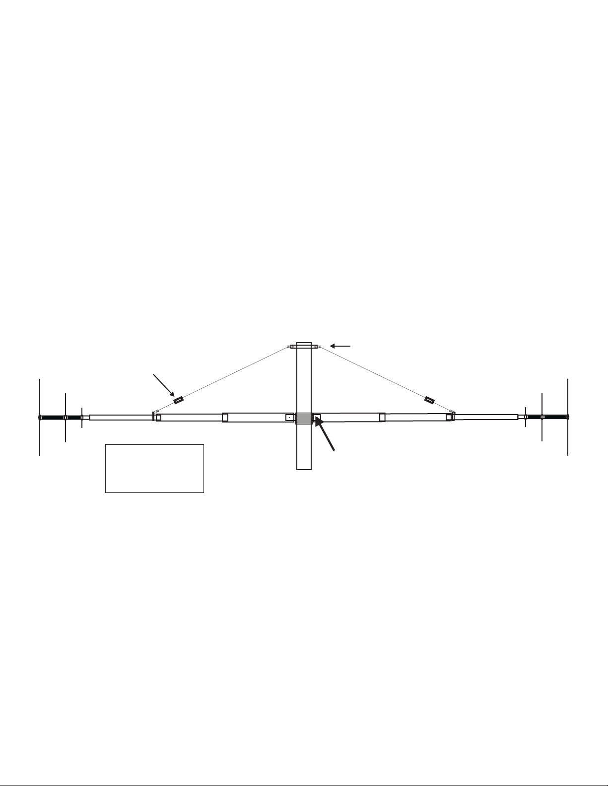
MFJ-1785 Rotatable Dipole
80, 40, 20 Meters
Boom support U-bolt
Ceramic
Insulator
T3
20M
40M
80M
T1
T2
T3
Drawing not to scale.
Tubing
1 1/2” x 72”
1 3/8” x 72”
1 1/8” x 60”
T2
3/16” cable
T1
T1
1 1/4” x 20”
Fiberglass rod
T2
T3
20M
40M
80M
Page 3

MFJ-1785 Rotatable Dipole Instruction Manual
MFJ-1785 Parts List
As you unpack your antenna you should find the parts in the following list.
Part Description QTY MFJ Part No.
Hardware Bag #1
Balun 1 80-1785-2
3/16 cable, 30 feet 1 13-1785-1
AV-640 Parts Pack 1 758-9200
Boom Bracket #1 1 735-1642
Boom Bracket #2 1 735-1644
5/16 U-bolt 2 758-9224
Ceramic Insulators, 3/16 2 MFJ-17A01
U-BOLT, 5/16 X 3 1/2 1 758-9220
Hardware Bag #2
1/4-20 x 1” bolt 6 662-1000s-HH
1/4-20 x 2”bolt 2 662-200s-HH
1/4-20 hex nut 8 705-2520s
1/4-20 split lock washer 8 711-2537s-SL
5/16” Split Lock Washer 6 711-3144s-SL
5/16” Hex Nuts 6 705-3118s
3/16” cable thimbles 4 713-9156
Boom Clamp 2 735-1785
Plastic spoke safety caps 42 765-1002
6-32 x 3/8” screws 50 656-0375s
6-32 kep nuts 50 705-0632s
#16 hose clamps 6 745-3116s
S.S. Strip, 2” x 5/8” 4 737-1785
U-Bolt saddle 1 758-9196
Tubing and Fiberglass
1 1/8 x 60” aluminum tube (T3) 2 810-1796-2
1 ¼ x 72” aluminum tube (T2) 2 20-1792-4
1 3/8 x 72” +1 ½ “x 48”aluminum tube (T1) 2 810-1785-2
1 ¼ x 20” solid fiberglass rod 1 811-1785-4
Loading Coils and Spokes
MFJ-1785 Loading coil assembly 2 811-1785-1C1
36” spokes 18 810-1798-5
30 3/4” spokes 16 810-1796-3c
12 3/4” spokes 8 810-1796-6
For installation, you will need some items not supplied with the antenna installation kit:
• A rigid mast or other mounting pipe between 1 3/4" and 2" outside diameter. (suitable materials
include TV mast sections, galvanized iron pipe, or heavy duty rigid conduit.)
• Quality low-loss 50-Ohm coax with a PL-259 from antenna to transmitter.
An Antenna Analyzer (MFJ-259B or similar), or SWR meter and transceiver.
1
Page 4

MFJ-1785 Rotatable Dipole Instruction Manual
MFJ-1785 80-40-20 Meter Rotatable Dipole
Introduction
The MFJ-1785 legal limit Rotatable Dipole operates on the 20, 40, and 80 Meter bands. The
antenna is thirty-three feet in length and can be turned by a medium duty antenna rotator.
WARNING: Improper installation and assembly can be hazardous! Read these instructions
thoroughly before attempting to assemble, install or operate this product! High power transmitting
devices produce voltages that can cause severe RF burns. Make certain the Antenna is installed out of
reach.
SPECIFICATIONS
The MFJ-1785 is 1/2 wavelength on the 20 meter band. The antenna uses efficient end loading coils with
capacitance hats for operation on the 40 and 80 meter bands. The end-loading coils are wound on
fiberglass forms with Teflon
The MFJ-1785 boom is made of 6063 T-6 aircraft strength aluminum tubing. The center insulator is 1.25
inch solid fiberglass rod. The boom is supported by 3/16” cable isolated from the boom with ceramic
insulators.
Assembly will require approximately one afternoon. The MFJ-1785 will radiate a maximum of 1500
watts PEP on 80-40-20 meters.
Electrical Specifications
Power
Band CW SSB 2:1 SWR BW
80m 1500 1500 25KHZ
40m 1500 1500 150KHZ
20m 1500 1500 1 MHz
Mechanical Specifications
Mast Size: 1 3/4 to 2” diameter
Overall Length: 34 feet
Turning Radius: 17 feet
TM
wire and capacitance hats.
2
Page 5

MFJ-1785 Rotatable Dipole Instruction Manual
CHOOSING A LOCATION FOR THE ANTENNA
For best performance on receiving and transmitting, mount the antenna in a clear location above or away
from buildings, towers, feedlines, utility wires, and other antennas. While your own ingenuity and
particular circumstances will determine the final mounting method, we'll pass along a few ideas for both
permanent installation and portable operation.
• Never mount this antenna in a location that will permit unsuspecting people to come in contact with
the loading coil spokes or any other part of the antenna.
• Never mount this antenna where a mechanical failure might allow the antenna to contact power lines
or other utility wires.
• Always ground the feedline at the point where it enters a building to a good earth ground for
lightning protection.
• Always ground the mast or tower base to a suitable ground rod.
WARNING: Always mount this antenna so that it is out of the reach of adults and children.
The capacitance elements can cause injury and/or severe RF burns.
Permanent Installation
The ideal installation is a rigid pole, roof mount, or tower that puts the antenna completely in the clear. If
the ideal installation is not possible, choose the best compromise. Heavy Duty TV mast, two inches in
outside diameter, heavy-duty rigid electrical conduit, and steel water pipes are suitable mast materials.
This antenna will mount on masts between 1- ¾” and 2” outside diameter. The use of soft or thin wall
masts is not recommended. These soft/ thin masts may fail and result in damage to property and possible
injury.
Note: The MFJ-1785 mast must extend 4 feet or more above the radiating element. This
extra height will give the support cables enough angle to provide sufficient support.
TOOLS AND TIME REQUIRED FOR ASSEMBLY
The estimated assembly time is two hours. Antenna assembly requires the following hand tools:
z #2 Phillips Screwdriver, for securing the 6-32 spoke screws
z 5/16” nut driver, for tightening the spokes and hose clamps
z 3/8” wrench for securing the balun u-bolt
z Two 7/16” wrenches for tightening the ¼ bolts on the mast mount assembly
z 1/2” wrench or deep well socket for tightening the u-bolts to the mast
z Heavy wire cutters/Lineman's Pliers for spoke trimming or a hack-saw
z Cable cutters for trimming the boom support cables.
z Pliers for holding the spoke ends as they are trimmed
z Safety Glasses
You also need two stable supports at least 36" tall (saw horses, trash cans, etc) during assembly, and a
short (10-12') temporary mast (1 3/4 to 2" OD) for temporary mounting during tuning..
SAFETY PRECAUTIONS:
3
Page 6

MFJ-1785 Rotatable Dipole Instruction Manual
WARNING! You can be killed if the antenna, feed-line, or the equipment used to install the
antenna accidentally contacts any utility lines. Never install an antenna near power lines!
1. Be careful while climbing and carrying the antenna. It is heavy enough to cause you to lose your
balance if it is handled too casually or if the capacitance spokes are snagged on a gutter, ladder, tree
limbs, etc.
2. Mount the antenna high enough so that it is out of reach. The ends of the capacitance spokes can
cause eye injury, serious RF burns or both. Higher installations will produce much better antenna
performance. Ground losses will be high at lower antenna elevations especially on 80-meters.
3. Make sure that the mast is sturdy enough to support the weight and the wind load.
ASSEMBLY AND INSTALLATION PROCEDURE
Refer to the figures in this manual during assembly. Assembly consists of putting together the
balun/center insulator assembly, connecting the aluminum radiating elements to the balun/center insulator
assembly. Loading coils and capacitance hats will then be assembled and coupled to the radiating
elements of the antenna.
After the antenna is assembled and adjusted for resonant frequency and SWR while mounted near ground
level, it can then be mounted on a tower or rooftop and given final adjustments.
WARNING: Wear safety glasses whenever working with this antenna.
Step-By-Step Procedure
1) Setup saw horses or other stable supports (plastic trash cans, chairs, folding tables, etc.) to
support the antenna during assembly. Thirty-six inches of height will keep the capacitance spokes
clear of the ground. Ground contact will bend the spokes.
2) Prepare a temporary 10-12’ ground-level mounting mast for easy initial testing and adjustment.
The mount must be capable of supporting the MFJ-1785 when it is fully assembled. A ladder or
other means of reaching the antenna will be necessary. Always be careful when using a ladder or
other structure.
3) Sort the antenna parts into groups of similar parts. Be sure all parts are available By comparing
them to the list on the inside cover of this manual.
4) Gather the tools needed for assembly on page 3
Temporary and Permanent Mounting
The MFJ-1785 should be mounted on a suitable mast 1 3/4 to 2”inch outside diameter. Make certain the
mast will support the weight and wind load of the antenna. The boom of the antenna should be mounted a
minimum of four feet from the top of the antenna mast. This distance is necessary for the cables to have
sufficient angle to provide support.
4
Page 7

MFJ-1785 Rotatable Dipole Instruction Manual
Mast Mount Assembly
• Parts
o (4) ¼-20 hex nuts
1/4-20 x 1” bolts
o (4) ¼-20 split lock washers
o (4) ¼-20 x 1” bolts
o (2) 5/16” x 3 ½” u-bolts
5/16” x 2 ” U-bolts
o (4) 5/16” split lock washers
o (4) 5/16” hex nuts
o Boom brackets #1 & #2
o 1 ¼” x 20” fiberglass rod
1/4-20 x 1” bolts
1 1/4” x 20” Fiberglass
• Tools
o (2) 7/16” wrenches
5) Place the two halves of the mounting bracket together. The solid fiberglass rod insulator will sit
between the two-halves.
6) Insert a ¼-20 x 1” bolt through each of the four corner holes of the mounting brackets place a ¼-
20 split lock washer and ¼” hex nut on each bolt. Do not tighten the bolts. Refer to the picture
above and below.
7) Insert the 2” u-bolts into the assembled bracket as shown in the picture above. The U-bolt should
be inserted so the saddle clamp fits properly around the antenna mast. Place a 5/16” lock washer
and then a 5/16” hex nut to secure the u-bolt in place. Do not tighten the u-bolt until you are
ready to mount the antenna in a temporary or permanent mast.
8) Insert the 1 ¼” x 20” solid fiberglass rod into the mounting bracket. The fiberglass should
extend from the bracket seven inches (7”) on each end. Refer to the figure above.
9) Rotate the fiberglass rod until the ¼” holes near the ends are oriented in the direction of the
bracket bolts.
10) Tighten the four (4) ¼-20 x 1” bolts to secure the bracket to the fiberglass rod. Make certain the
bracket is in the center of the rod and the rod is oriented as described in step 8.
Note: The mast mount assembly should be temporarily mounted to a mast for the remainder of
assembly. The temporary mast should be approximately 2 inches in diameter and 10 feet in height.
The bracket should be mounted 4 feet from the top of the temporary mast.
11) Insert the temporary mast through the u-bolts placed on the bracket in step 7. Secure the 5/16
nuts with a ½” wrench. Make certain the bracket is placed four feet from the top of the mast.
Tighten the u-bolts being careful not to squeeze your support mast. Make certain the mast will
support the weight and wind load of the MFJ-1785.
5/16” X 2” U-bolts
1/4-20” X 1” bolts
5/16” X 2” U-bolts
1/4-20” X 1” bolts
5
Page 8

MFJ-1785 Rotatable Dipole Instruction Manual
Balun Assembly
The Balun for the MFJ-1785 comes pre-assembled. It should be mounted just below the mast
mount assembly on your temporary or permanent mast. Caution should be used when removing
the balun from the packing material being careful not to damage the wires.
12) Remove the single u-bolt, two lock washers and hex nuts from the parts pack. These
items were packed in a separate bag within one of the parts packs.
13) Place the balun on the antenna mast below the antenna mount. The V-shaped side of the balun
should face the temporary/permanent mast.
14) Place the u-bolt around the antenna mast and insert it into the mounting holes located on the side
of the balun.
15) Place a lock-washer and hex nut on each side of the u-bolt. Secure the balun with a 3/8” wrench.
Make certain the placement of the balun allows the wires to reach the 1/4” holes near the ends of
the fiberglass rod.
16) Secure the hex nuts in place, be careful not to over tighten the nuts, damage may occur to the
balun case. The Balun wires will be attached to the antenna in step19 below.
Tubing Assembly
The MFJ-1785 antenna boom uses six pieces of aluminum tubing. Below is a list of parts
for assembling the MFJ-1785 antenna boom.
• Parts
o (2) ¼-20 hex nuts
o (2) ¼-20 split lock washers
o (2) ¼-20 x 2” bolts
o (6) #16 hose clamps
o (2) T1 3/8 x 60 +1 ½ x 48” aluminum tubing
o (2) 1 3/8 x 72” +1 ½ “x 48”aluminum tube (T1)
o (2) 1 ¼ x 72” aluminum tube (T2)
o (2) 1 1/8 x 60” aluminum tube (T3)
• Tools
o (2) 7/16” wrenches
o (1) 5/16” nut driver
Note: The mast bracket and balun should be mounted securely to a temporary or
permanent mast at this point. Make certain the bracket is located 4 feet from the top
of the mast.
17) Place one of the T1 aluminum tubes onto the fiberglass rod of the mast bracket located on your
temporary mast. Refer to figure 5 below. The drilled hole of the tubing should align with the
drilled hole in the fiberglass rod. Be certain to place the end of the tubing with the hole drilled for
a ¼” bolt over the fiberglass rod.
18) Align the ¼” hole in the tubing with the ¼” hole in the fiberglass.
19) Insert one of the ¼” x 2” bolts through the solder lug of the balun wire. Place the bolt through the
tubing T1 and the fiberglass.
20) Secure the bolt with a ¼” split lock washer and ¼-20 hex nut. Use two 7/16 wrenches to tighten
the bolt securely. Follow the same procedure (steps 17-19) on the opposite side of the mast
bracket.
21) Place a #16 hose clamp over both T1 aluminum tubes placed in the previous 2 steps.
6
Page 9

MFJ-1785 Rotatable Dipole Instruction Manual
22) Insert aluminum tube T2 into the slotted end of the T1 tube approximately 4 inches. Place the
#16 hose clamp in the middle of the slot and secure the clamp with a 5/16” nut driver. Follow the
same procedure for the opposite side of the mast bracket.
23) Place a #16 hose clamp over both T2 aluminum tubes placed in the previous steps.
24) Insert aluminum tube T3 into the slotted end of the T2 tube approximately 4 inches. Place the
#16 hose clamp in the middle of the slot and secure the clamp with a 5/16” nut driver. Follow the
same procedure for the opposite side of the mast bracket.
25) The overall length of the antenna should be approximately 33 feet (16 ½ feet each side). Adjust
each section of the tubing to obtain this approximate length. Make certain a minimum of 4 inches
of tubing is inserted within each section. Tighten all hose clamps when finished.
Boom support U-bolt
e
l
b
a
c
Ceramic
Insulator
”
6
1
/
3
T3
T2
T1
T
1
2
T
T3
Tubing
T1
T2
T3
1 1/2” x 72”
1 3/8” x 72”
1 1/8” x 60”
1 1/4” x 20”
Fi be rgl ass ro d
Figure 5
Cable Support Assembly
Thirty feet of 3/16 cable is shipped with the MFJ-1785 to provide support. The cable must be
installed to prevent sag and to prevent damage to the antenna. Ceramic insulators are provided
to isolate the radiating elements of the antenna from the antenna support mast. See the adjacent
figures. Follow the instructions below for assembly.
o (2) 5/16” x 3 ½” u-bolts
o (1) U-Bolt saddle
o (2) 5/16” split lock washers
o (2) 5/16” hex nuts
o (4) S.S. Strip, 2” x 5/8”
o (1) 3/16 cable, 30 feet
o (4) 3/16” cable thimbles
o (2) Ceramic Insulators, 3/16
o (1) Boom Clamp
• Tools
o (2) 7/16” wrenches
o 9/16” wrench
o Cable cutter
o Pliers
26) Insert the remaining 5/16” by 3 ½”” u-bolt through the saddle bracket.
27) Place a 2”x 5/8” S.S. flat strip on each of the u-bolts as indicated in picture to the above.
28) Place a 5/16 split lock washer and 5/16 hex nut onto the u-bolts and hand-tighten them. Be sure
to leave enough space for your mast to go through the u-bolt and saddle bracket.
7
Page 10

MFJ-1785 Rotatable Dipole Instruction Manual
29) Place the assembled cable support assembly over the top of your permanent or temporary antenna
support mast. The assembly should be 4 feet above the boom of the antenna. Tighten the u-bolt
in place with a 9/16” wrench.
30) Place one of the circular clamps over the ends of both T3 tubes.
31) Place a S.S. Strip (2” x 5/8”) onto the ¼-20 x 1” bolt. Secure it with a ¼ split lock washer and ¼-
20 hex nut. Refer to the picture below. Secure the nut and bolt with a 7/16” wrench.
32) Remove the plastic ties on the 3/16 Galvanized cable. Straighten the cable and cut it into two
equal length pieces with cable cutters.
33) Carefully spread the ends of the cable thimbles with pliers. Spread the thimble just enough to
pass it freely through the hole of the flat stainless steel strips placed in step on step 27. When the
thimbles are placed through the stainless steel strips close them back.
34) Pass one end of the cable through the hole where the thimble was just placed. Eight inches of
cable should be passed through each side. Make certain that the cable is inserted in the thimble.
35) Wrap the cable 5-7 times back around itself in tight wraps to secure the end. Any excess cable
can be wrapped on the cable or removed if desired. Repeat this step for both sides.
36) The next step is to place the ceramic insulators near the end of the cables. The cables should
reach the clamps placed on T2 and T3 earlier. The clamp should remain loose until the insulators
are secured to the cable. Refer to the above pictures.
37) The insulators should be placed as close to the radiating elements as possible. Three to four
inches is sufficient. Cut the cable and make adjustments as necessary. Refer to the above
pictures. Be certain to wrap the cable back on itself 5-7 wraps. Make certain to make tight wraps.
Wrap or remove any access cable. Repeat this procedure for the other side of the antenna.
38) Attach the cable to the boom using a 1/4-20 x 1” bolt, lock washer, and hex nut. Adjust the
tightness of the cable by sliding the bracket on the boom shown in the above picture.. The cables
on both sides of the antenna should be of equal. Slight adjustments can be made to the cable by
loosening and sliding the clamps on the antenna boom.
Loading Coil Assembly
IMPORTANT: Use a 5/16” nut driver to tighten the capacitance spokes in place. Tighten
by hand only. A high torque electric screwdriver will shear the screws.
NOTE: You can ease your tuning effort by pre-marking the outer ends of the spokes prior
to installation. You can do this by placing 1”, 2”, and 3” marks on one end of each spoke
using a black permanent marker pen. Then subdivide these marked sections into ¼”
segments using a red permanent marker pen.
NOTE: Install the spokes through the rings until they come in contact with the fiberglass
rod. This will give you about 1/4” of spoke available to slide back out should you trim too
much off a spoke during tuning.
39) Remove the loading coil assemblies from there protective wrapping.
40) Install the 6-32 screws in all rings of both loading coil assemblies, loosely holding them in place
with their associated 6-32 kep nuts.
41) Install eight 36” spokes in the outer 80-meter rings of both loading coil assemblies. With a 5/16”
nut driver, tighten the nuts until the spokes are snug.
8
Page 11

MFJ-1785 Rotatable Dipole Instruction Manual
42) Install eight 30.75” spokes in the remaining locations on the middle 40-meter rings of both
loading coil assemblies. With a 5/16” nut driver, tighten the nuts until the spokes are snug.
43) Install four 12.75” spokes in the inner 20-meter rings of both loading coil assemblies. With a
5/16” nut driver, tighten the nuts until the spokes are snug.
Loading Coil Assembly
44) Loosen the mounting screw indicated in the loading coil assembly figure above so that the aluminum
radiator can be placed under the aluminum tab. Slide the aluminum radiator tube until it contacts the
mounting screw that was just loosened. Tighten the mounting screw. Do not over-tighten this screw
or you may BREAK the fiberglass form. Slide the hose clamp over the tab and tighten the hose
clamp to firmly attach the loading coil assembly to the aluminum radiator.
45) Double check the tightness of all the hardware you installed and then mount the antenna on the short
temporary tuning mast.
46) Tune the antenna as discussed in the next section.
47) Mount the antenna in the final location. Slight re-tuning may be necessary.
FREQUENCY AND SWR ADJUSTMENT
An SWR analyzer such as the MFJ-259B or equivalent is highly recommended when tuning the MFJ-
1785. While a transceiver and SWR meter can be used, an SWR analyzer will significantly decrease the
time and effort necessary to tune the antenna.
The MFJ-1785 covers wider frequency ranges on the higher bands, and narrower segments on the lower
frequency bands. The 80 meter band has the narrowest range of operation (approximately 25 KHz) and is
the most sensitive to adjustments.
The entire antenna must be accessible during initial coarse tuning and testing. Any repair or adjustment
to the antenna after it is installed on a tall support will make adjustments difficult and time consuming. It
is best to install the antenna on a short temporary mast or pipe that is located in a reasonably clear
location for tuning. The antenna should be mounted horizontally10-12 feet above ground to make tests
and adjustments easy.
During tuning, feed the antenna with a reasonably short length of good quality 50 ohm coaxial cable to
ensure proper results. If using a transceiver and SWR meter, set the transceiver to the lowest power
possible when making measurements.
9
Page 12

MFJ-1785 Rotatable Dipole Instruction Manual
The normal resonant frequency of this antenna is at or just below the bottom of each amateur
band. This allows the user to "trim" a small amount off the capacitance spokes to raise the resonant
frequency. Conversely, adding a longer capacitance spoke will lower the resonant frequency of a loading
assembly. Spare spokes are included in case you need to lower the resonant frequency of the antenna.
CAUTION: Always start tuning on 80 meters and adjust each band progressively higher in
frequency. Adjustment of a lower frequency band will always have the most effect on the next higher
frequency band. The tendency of the interaction is that if you move one band higher ALL the other bands
move higher, but only very slightly. It is always best to "shoot for" the lowest end of the range you
intend to use and "trim in" by adjusting the outermost (80 meter) loading coil assemblies after the antenna
is in its final location.
NOTE: When you tune the antenna at a height of 10-12 feet, you will find that the
resonant 80 meter
frequency will shift up in frequency 30-50 kHz when the
antenna is raised to the final height. However, when the plastic end caps are
installed on the ends of the spokes, the resonant frequency on all
bands is lowered
30-50 kHz
Tuning the Antenna
1) Measure and record the frequency of lowest SWR for each band. The lowest SWR should be at or
below the bottom end of each HF band. The SWR should be below 2:1 at resonance on each band.
The following is a typical chart for initial measurements of a new antenna before tuning:
80 M 1.7:1 at 3.49 MHz
40 M 1.4:1 at 6.99 MHz
20 M 1.2:1 at 13.99 MHz
If you are using a transceiver and SWR meter, the initial resonant frequency may be lower than you can
measure. If so, remove one spoke from each loading coil assembly to raise the resonant frequency.
Measure this resonant frequency and calculate the approximate resonant frequency as if the spokes were
in place using the trimming chart (step 2) on the next page.
WARNING: You will be trimming the outer ends of the spokes. The sharp sends can cause
a hazard until they are covered with the plastic caps. Therefore it is VERY IMPORTANT
to wear safety glasses when trimming the spokes, or when working near the antenna.
CAUTION: Use a pair of pliers to hold the outer piece of each spoke that is to be cut off so
as to keep the cut piece from flying off and causing injury.
The following tips will help you obtain a better SWR on 80 meters than the tuning method used on other
bands. On 80 meters the lowest SWR is usually not obtained with left and right loading spokes adjusted
to the same frequency.
Low End of 80 Meters: If you desire operation below 3.7 MHz, the lowest SWR will be obtained by
adding two long spokes to ONLY ONE
spokes on opposite sides of the coils. Thirty-six inch 80 meter spokes from both coils can then be
of the 80 meter loading coil assemblies. It is best to add the
10
Page 13

MFJ-1785 Rotatable Dipole Instruction Manual
trimmed equal amounts to resonate the antenna. This will leave one loading coil assembly with two
spokes that are longer than those on the other loading coil assembly.
High End of 80 Meters: If you desire operation above 3.75 MHz the lowest SWR will be obtained by
trimming the spokes on one of the loading coils only until the antenna is resonant approximately 15 KHz
below the operating frequency.
Middle of 80 Meters: For operation between 3.6 and 3.8 MHz, add ONE long spoke to one of the
loading coil assemblies only.
NOTE: Before trimming the spokes simply remove one spoke on each side of the from
each of the loading coils. For example, remove one spoke from the outside 80 meter spoke
rings. Check the SWR and frequency to see how this affects your measurements. This can
simplify the tuning process. Once a suitable frequency and SWR is obtained use the below
steps to fine tune your antenna for your desired frequency.
2) Begin tuning by trimming one 80 meter spoke from each end of the antenna by cutting off small,
equal sections from the end of the spoke until the antenna resonates approximately 5 KHz below the
desired operating frequency. Use the chart below to approximate the amount of spoke to be trimmed.
Trimming only one spoke from the top or bottom results in half the frequency change.
80 M: 1" trimmed off a pair of spokes equals approximately 10 KHz
40 M: 1" trimmed off a pair of spokes equals approximately 100 KHz
20 M: 1" trimmed off a pair of spokes equals approximately 175 KHz
Note: Typical final spoke lengths for the low end of each HF band are shown in the table below.
3) If the SWR is acceptable at the desired operating frequency, the adjustment for that band may be
skipped.
4) Now tune progressively higher frequency bands by trimming pairs of spokes on each of the two
loading coil assemblies. Re-check the tightness of all spoke screws.
5) Final frequency adjustments can be made by trimming spokes on one of the loading coil assemblies
only if desired, though symmetrical trimming is preferred. The minor adjustment of one side only
without the symmetrical trimming of the other side is perfectly acceptable so long as the frequency is
changed less than 30 KHz on 80 meters and 80 KHz on the higher bands during final adjustment.
Moving the resonant frequency too far with only the spokes on one loading coil assembly will
increase the SWR of the antenna at the resonant frequency.
NOTE: The spokes can also be bent toward another spoke in the same mounting ring to raise the
frequency slightly without cutting.
6) When all tuning is complete, install the plastic end caps on the outer ends of all spokes. Note that the
plastic end caps will lower the resonant frequency on all HF bands by 30-50 kHz. The plastic end
caps should fit snugly on the spokes. Should a cap fit too loosely, add a drop of glue to the spoke
end before sliding on the cap.
TYPICAL FINAL SPOKE LENGTHS FOR HF CW BAND OPERATION
• 80 Meters: 31” (full length) for all 16 spokes
• 40 Meters: 29-3/4” length for all sixteen spokes.
11
Page 14

MFJ-1785 Rotatable Dipole Instruction Manual
• 20 meters: 12” length for all eight spokes.
GROUNDING CONSIDERATIONS
Although this antenna is designed to operate efficiently without the requirement of an earth ground, safety
grounding must still be provided to protect equipment, property and persons from the hazards of lighting strikes and
other weather related electrical discharges. In addition, the coaxial cable feeding the antenna should have the shield
grounded to eliminate the risk of any indoor equipment failure allowing hazardous voltages that could create a
shock hazard.
Adequate protection can be accomplished by grounding the shield of the coax to a good earth ground where it enters
the building, or directly burying the cable in th e earth for several feet before it enters the building. For maximum
lightning protection, the coaxial cable should be totally disconnected from the station during threatening weather
conditions.
A less effective method of protecting station equipment is to install an in-line coaxial lightning arrestor with a heavy
duty ground wire to a suitable earth ground, or a safety switching system as part of the basic ham station equipment.
MAINTENANCE
Your antenna is constructed of heavy-duty non-corrosive materials and should withstand normal climates for many
years. The use of some type of coaxial connector moisture protection is recommended at the balun coax connection,
and also around the center-feed connections, especially in coastal areas where salty mist is commonplace.
GE makes a pure, silicone grease called "SILICONE DIALECTRIC COMPOUND" that can be applied
SPARINGLY to the threaded area of the female connector. This compound, or even a clear silicone heatsink
compound, will prevent moisture from entering the connector through the threads and protect the connectors from
corrosion. This is the same type of sealer that commercial antenna installers and CATV companies use with great
success.
Plast-Dip
insulating/waterproofing connectors, and can be easily peeled off when desired.
A less desirable, but still adequate sealer is the automobile seam sealer commonly sold as "coax seal". This is a
semi-pliable black or white sealing compound.
When installing any "coax seal", NEVER completely cover the barrel of the coax connector. The sealer should
ONLY be placed near the junction of the threaded part of the chassis connector and the knurled area of the male
connector. This will leave the bottom of the male outer sleeve open and permit the connector to "breathe" so it does
NOT collect moisture!
TM
and Liquid Electrical TapeTM, available at your local hardware store, also do an excellent job of
TECHNICAL ASSISTANCE
If you have any problem with this unit first check the appropriate section of this manual. If the manual does not
reference your problem or your problem is not solved by reading the manual, you may call MFJ Technical Service
at 662-323-0549 or the MFJ Factory at 662-323-5869. You will be best h elped if you have your unit, manual and
all information on your station handy so you can answer any questions the technicians may ask. You can also send
questions by mail to MFJ Enterprises, INC., 300 Industrial Park Road, Starkville, MS 39759; by Facsimile (FAX) to
662-323-6551; or by email to techinfo@mfjenterprises.com. Send a complete description of your problem, an
explanation of exactly how you are using your unit, and a complete description of your station.
12
Page 15

MFJ-1785W Rotatable Dipole Instruction Manual
NOTES:
12
Page 16

MFJ-1785W Rotatable Dipole Instruction Manual
FULL 12-MONTH WARRANTY
MFJ Enterprises, Inc. warrants to the original owner of this product, if manufactured by MFJ Enterprises,
Inc. and purchased from an authorized dealer or directly from MFJ Enterprises, Inc. to be free from
defects in material and workmanship for a period of 12 months from date of purchase provided the
following terms of this warranty are satisfied.
1. The purchaser must retain the dated proof-of-purchase (bill of sale, canceled check, credit
card or money order receipt, etc.) describing the product to establish the validity of the warranty
claim and submit the original or machine reproduction of such proof of purchase to MFJ
Enterprises, Inc. at the time of warranty service. MFJ Enterprises, Inc. shall have the discretion to
deny warranty without dated proof-of-purchase. Any evidence of alteration, erasure, of forgery
shall be cause to void any and all warranty terms immediately.
2. MFJ Enterprises, Inc. agrees to repair or replace at MFJ's option without charge to the
original owner any defective product provided the product is returned postage prepaid to MFJ
Enterprises, Inc. with a personal check, cashiers check, or money order for $10.00 covering
postage and handling.
3. MFJ Enterprises, Inc. will supply replacement parts free of charge for any MFJ product
under warranty upon request. A dated proof of purchase and a $8.00 personal check, cashiers
check, or money order must be provided to cover postage and handling.
4. This warranty is NOT void for owners who attempt to repair defective units. Technical
consultation is available by calling (662) 323-5869.
5. This warranty does not apply to kits sold by or manufactured by MFJ Enterprises, Inc.
6. Wired and tested PC board products are covered by this warranty provided only the
wired and tested PC board product is returned. Wired and tested PC boards installed in the
owner's cabinet or connected to switches, jacks, or cables, etc. sent to MFJ Enterprises, Inc. will be
returned at the owner's expense un-repaired.
7. Under no circumstances is MFJ Enterprises, Inc. liable for consequential damages to
person or property by the use of any MFJ products.
8. Out-of-Warranty Service: MFJ Enterprises, Inc. will repair any out-of-warranty product
provided the unit is shipped prepaid. All repaired units will be shipped COD to the owner. Repair
charges will be added to the COD fee unless other arrangements are made.
9. This warranty is given in lieu of any other warranty expressed or implied.
10. MFJ Enterprises, Inc. reserves the right to make changes or improvements in design or
manufacture without incurring any obligation to install such changes upon any of the products
previously manufactured.
11. All MFJ products to be serviced in-warranty or out-of-warranty should be addressed to
MFJ Enterprises, Inc., 300 Industrial Park Rd, Starkville, Mississippi 39759, USA and must
be accompanied by a letter describing the problem in detail along with a copy of your dated proofof-purchase and a telephone number.
12. This warranty gives you specific rights, and you may also have other rights, which vary
from state to state.
 Loading...