


MFJ-1780 Box Fan Loop Antenna Instruction Manual
MFJ-1780
Box Fan
Portable loop Antenna
WARNINGS ................................................................................................................... 2
THEORY OF OPERATION........................................................................................... 3
PATTERNS, POLARIZATION AND LOCATION....................................................... 3
NULLLING UNWANTED SIGNALS:.......................................................................... 4
Vertical Polarization: ...................................................................................................... 4
Horizontal Polarization: .................................................................................................. 5
OUTDOOR USE............................................................................................................. 5
INDOOR USE................................................................................................................. 6
CONTROLLER BOX INSTALLATION ....................................................................... 7
CONTROLLER BOX OPERATION ............................................................................. 7
TESTING AND OPERATION....................................................................................... 9
GENERAL OPERATION AND TROUBLESHOOTING ............................................. 11
TUNING WHEN YOU DO NOT KNOW THE LAST OPERATING FREQUENCY . 11
TUNING WITH A KNOWN DIRECTION OF FREQUENCY MOVEMENT ............ 12
TROUBLE SHOOTING................................................................................................. 12
TECHNICAL ASSISTANCE......................................................................................... 13
1
MFJ-1780 Box Fan Loop Antenna Instruction Manual
MFJ-1780
Box Fan
Portable loop Antenna
continuos coverage 14.0MHz -- 30.0MHz
CAUTION! Do Not Attempt Operation Of This Unit Before Reading All
Instructions,
this antenna can be hazardous
The MFJ Box Fan Loop is the best performing portable small space antenna available to amateurs
today. This antenna has the same size and shape as a 2x2 foot box fan. It has a carrying handle and
features an indoor tuning unit. All tuning and control voltages are coupled to the antenna through the
coaxial feedline for simple, neat, one wire installation.
The Box Fan loop antenna element is constructed from wide, thick wall Aluminum sheeting. Every
current carrying joint is welded to eliminate high resistance pressure contacts that reduce efficiency.
The Box Fan loop is tuned with a superb all welded, low-resistance, high current, butterfly tuning
capacitor.
WARNINGS
especially the warning section below. Improper use of
!!!!!!!
- Keep this antenna out of reach of adults, children, and animals. Any
contact with this antenna while transmitting will cause severe RF
burns, and voltages that kill.
- Never place this antenna close to electric power lines or utility wires.
- Do not stay near the antenna if you are transmitting RF over 10 watts of
power, especially above 14 MHz.
- Keep the antenna away from you to prevent exposure to high levels of
electromagnetic field radiation.
- Keep this antenna away from water and moist areas, water and moisture
increase conductivity which in turn increases the risk of RF burn and
possibly death!!!
- MFJ-1780 is not weather proofed! Antenna will be damaged if exposed to
water and moisture.
- Never operate this antenna near RF sensitive medical devices such as
pacemakers.
- Do not touch the antenna metallic surface while transmitting even on very
low power, the metallic surface of the antenna is the radiating element
itself. Be aware, you can be killed!!
- Keep the feedline of this antenna away from utility lines.
2
MFJ-1780 Box Fan Loop Antenna Instruction Manual
THEORY OF OPERATION
When resistive losses in a small loop antenna are kept low, a small loop antenna will transmit nearly as
well as a full size dipole. MFJ was able to make this small loop antenna radiate nearly as well as a full
size dipole by paying special attention to the electrical and mechanical construction of this antenna.
MFJ uses heli-arc welds on all joints to eliminate resistive pressure connections in the antenna. A
specially constructed butterfly capacitor using arc-welded construction has much lower loss resistance
than conventional, less expensive, pressure contact, air variable capacitors.
The care and expense used in selecting the best materials, not the most convenient materials, has
resulted in an extremely efficient small size antenna. Extensive "on the air" tests have confirmed that
most stations can detect little difference between the signal from the MFJ Box Fan Loop and the signal
from a larger size none-portable loop at the same height.
PATTERNS, POLARIZATION AND LOCATION
WARNING
- Keep this antenna out of reach of adults, children, and animals. Any
contact with this antenna while transmitting will cause severe RF burns
and voltages that kill.
- Never place this antenna close to electric power lines or utility wires.
- Do not stay near the antenna if you are transmitting RF over 10 watts of
power, especially above 14 MHz.
- Keep the antenna away from you to prevent exposure to high level of
electromagnetic field radiation.
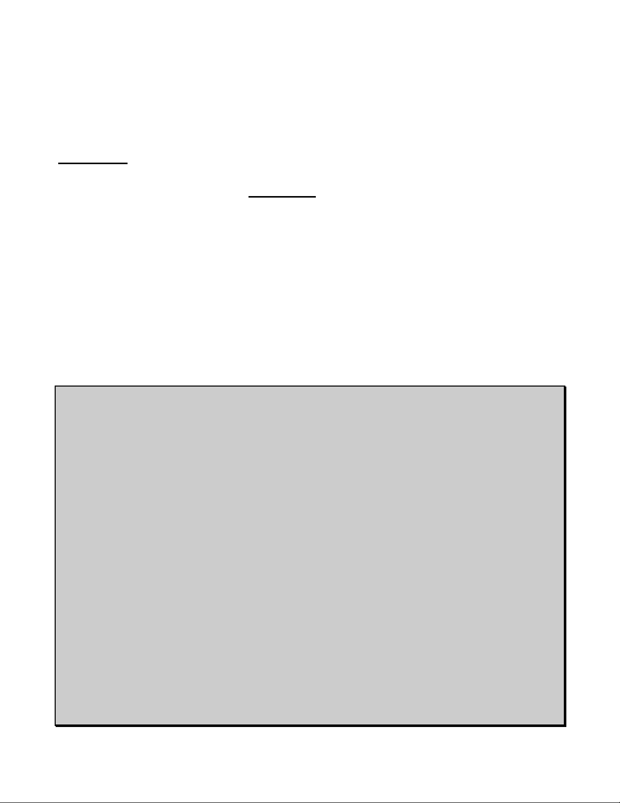
The Box Fan loop antenna can
be used to provide either
vertical or horizontal
polarization. To obtain vertical
polarization the loop should be
placed standing up on its edge.
To obtain horizontal
polarization the loop should be
laid flat on its side over a non
conductive surface. See
Figure 1.
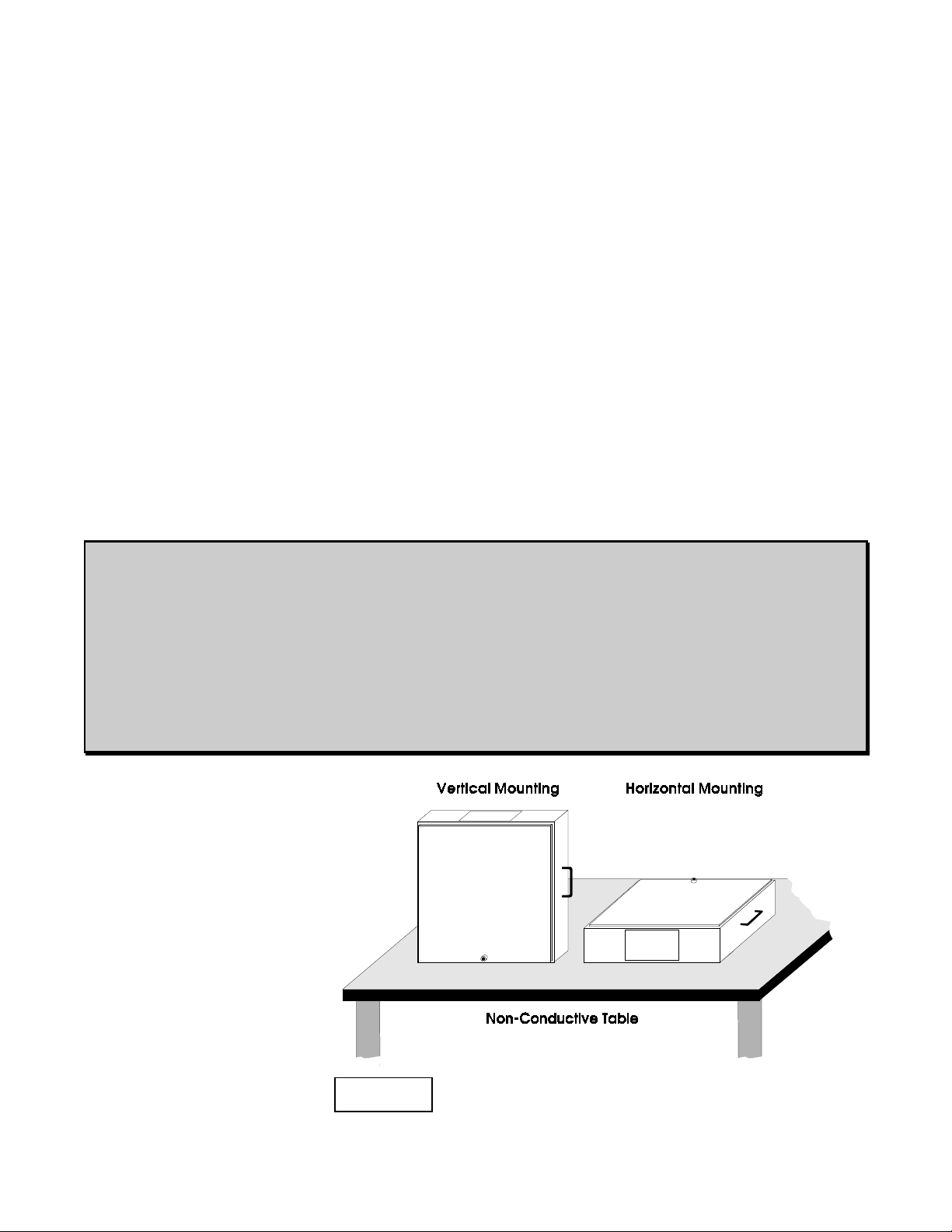
The radiation pattern of a small loop antenna is essentially omni-directional with
the exception of two very narrow nulls in the axis of the loop. If you visualize the
Figure 1
3
MFJ-1780 Box Fan Loop Antenna Instruction Manual
loop as a wheel, the nulls are in the same directions
that the wheel's axle would run. Signals will be
attenuated more than 10 dB if they arrive within 15
degrees of the axis of the loop. See Figure 2.
- In general this antenna, like most others, should be
placed as far away from and as high above other
objects as possible. The null (or broadside axis) of
the loop should be placed in line with the direction
that you do not want to transmit or receive. If the
loop can not be placed more than 15 feet above
ground level the best placement arrangement will
be with the loop placed vertically (sitting on its
edge). Otherwise, (higher than 15 feet) it is
possible to mount the antenna horizontally.
Figure 2
NULLLING UNWANTED SIGNALS:
In the vertical position, the Box Fan loop nulls can be used to reduce interference (if receiving) from
undesired directions if the unwanted signal is coming from a fixed direction and wave angle, or to
minimize interference (if transmitting) caused by the antenna itself to other household electronics
equipment.
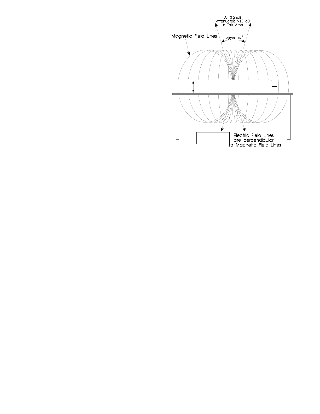
Other examples of using the null can be understood if we consider a loop antenna placed horizontally
on a second or higher floor of a building. By placing the antenna horizontally on the middle of the attic
the null can be positioned directly below and the antenna (through the building). This placing
arrangement helps receiving by reducing the noise pick-up from devices in the building and helps
transmitting because energy is not coupled into the building's lossy structure. RFI in the building will
also be reduced because the signal transmitted into the building is
weaker. See Figure 3.
VERTICAL POLARIZATION:
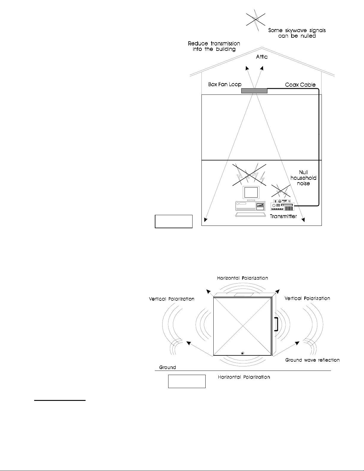
When the loop is placed to provide vertical polarization the pattern is vertically polarized in line with
the loop element. There will still be a large amount of horizontally polarized radiation broadside to the
loop, especially if the ground under the loop is less than perfect or if the loop is placed some distance
above ground.
The broadside horizontal radiation that occurs in a small vertical loop is mostly above 10 degree wave
angles and extends straight above the loop and to the opposite 10 degree elevation point. True vertical
polarization occurs only in line with the loop. As you move around the loop towards the sides, the
pattern skews and eventually becomes completely horizontal broadside to the loop. See Figure 4.
Unlike linear verticals, vertically polarized small loops also radiate straight up and down from the
antenna. This high angle of radiation can be used to cover short distances by sky wave. The high angle
horizontal radiation in a vertically polarized loop antenna occurs because the ground below the loop is
4
MFJ-1780 Box Fan Loop Antenna Instruction Manual
either too far away or is not a good enough RF
reflector to cancel the horizontal radiation
component of the vertical loop.
HORIZONTAL POLARIZATION:
Horizontal mounting of the loop antenna results in
an omni-direction, horizontally polarized pattern
that has a null straight up in the air and straight
below the center of the antenna. This means that
any ground reflection will tend to cancel the
radiation along the horizon, and also at low wave
angles unless the loop is mounted some distance
above ground.
Note: Do not expect the best results if you mount
this loop antenna horizontally less than 15
feet above ground.
Since ground wave signals only propagate well
along the earth when they are vertically
polarized, a horizontally polarized loop
may not respond to some local noise
sources. Like all other antennas, a small loop is generally a quieter receiving antenna when horizontally
polarized. This also means that a horizontally polarized loop is not a good choice for local ground
wave communications. It is an excellent choice for medium to long distance sky wave
communications, however.
Figure 3
OUTDOOR USE
Note : The MFJ Box Fan Loop can
be used outdoor only in good
weather conditions ( not in windy or
stormy weather).
WARNING
When operating outdoors it is IMPORTANT to:
Figure 4
5
 Loading...