


MFJ-1778 G5RV Multiband Antenna
Table of Contents
Introduction..................................................................................................................... 1
Theory Of Operation....................................................................................................... 1
80 meter band:..................................................................................................... 1
40 meter band:..................................................................................................... 1
30 meter band:..................................................................................................... 2
20 meter band:..................................................................................................... 2
17 meter band:..................................................................................................... 2
15 meter band:..................................................................................................... 2
12 meter band:..................................................................................................... 2
10 meter band:..................................................................................................... 2
160 meter band:................................................................................................... 3
Tools And Time Requirements ....................................................................................... 3
Safety Precautions:.......................................................................................................... 3
Installing The Antenna.................................................................................................... 4
Horizontal Antenna ............................................................................................. 4
Inverted "V" Antenna:......................................................................................... 4
Sloper Antenna:................................................................................................... 5
160 Meter Operation: .......................................................................................... 5
Balun Requirement ......................................................................................................... 6
Air Wound Balun Construction ...................................................................................... 6
Tuning The Antenna ....................................................................................................... 7
Grounding Considerations .............................................................................................. 7
Maintenance .................................................................................................................... 7
Technical Assistance....................................................................................................... 8
i

MFJ-1778 G5RV Multiband Antenna
MFJ-1778 G5RV
160 through 10m Antenna
Introduction
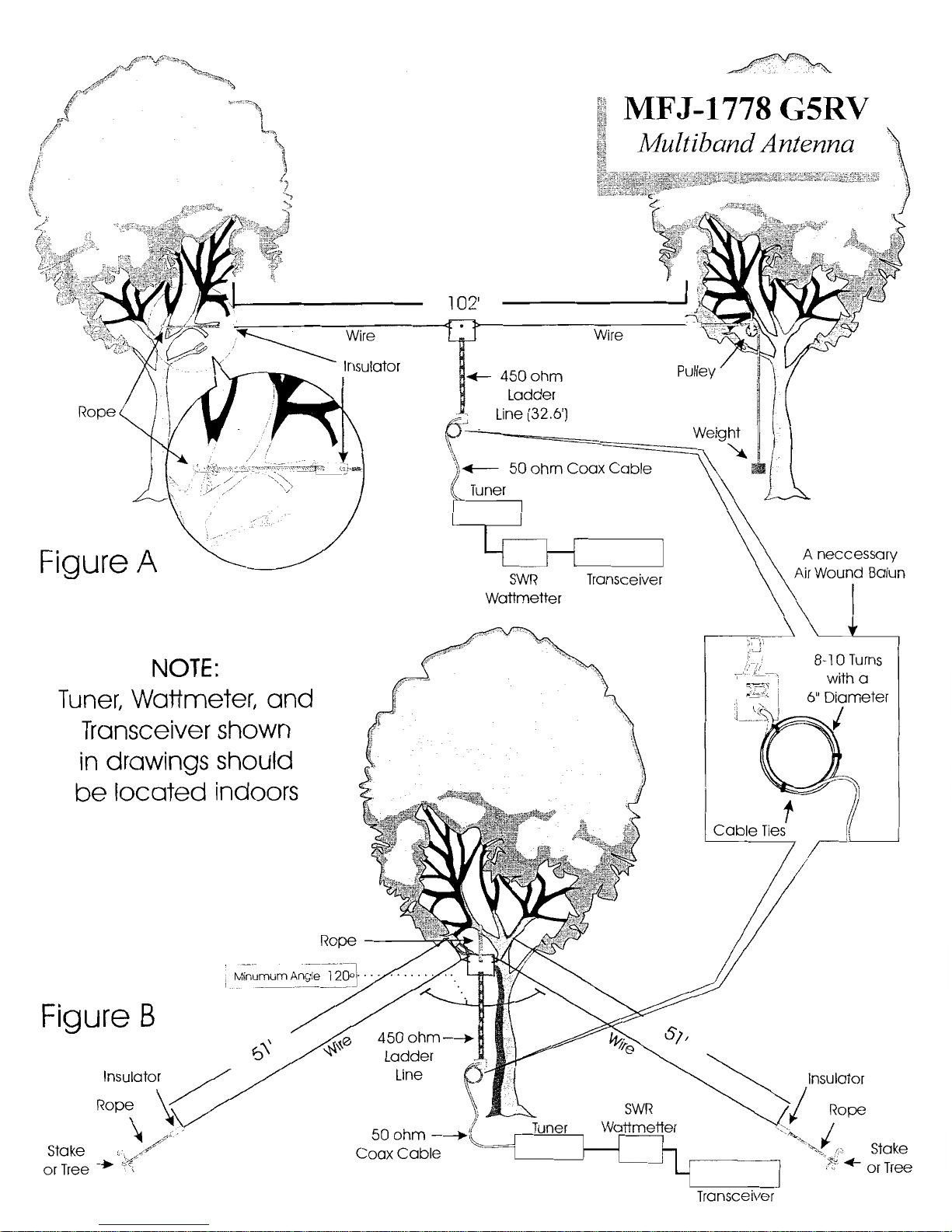
The G5RV antenna is a multi-band center-fed dipole antenna capable of 1500 Watts. It was originally
designed to operate as a 3/2 wavelength center fed antenna for 14 MHz, but amateurs soon discovered
it would offer reasonable performance on many other bands. The MFJ-1778 (G5RV) consists of a 102
foot flat top fed with a 32.5 foot 450 ohm matching section ending in an SO-239 coaxial connector.
The 450 ohm balanced transmission line serves as a 1:1 transmission line transformer on 14 MHz. The
SWR is approximately 2:1 at 14 MHz. The same balanced line section acts like a transmission line
impedance matching section on the other HF bands. This antenna generally requires the use of a
suitable matching network (antenna tuner) since the SWR of the G5RV is almost certainly not 1:1 on
any band. The use of a tuner will guarantee maximum performance from solid state exciters.
The G5RV is a balanced antenna that is fed by an unbalanced coaxial line. This feed system causes
unwanted parallel RF currents to appear on the shield of the coaxial feedline. A choke type balun
should be used with this antenna to eliminate or reduce the undesirable parallel feedline currents.
Failure to use a choke balun may result in RFI, RF feedback, or other symptoms of RF "in the shack".
The Balun Requirement section describes how to construct a choke balun for this antenna.
WARNING:
Contact with any part of this antenna can cause RF burns or other injuries.
Always mount this antenna so that it is out of the reach of adults and children.
Theory Of Operation
A description of how the G5RV functions on each band follows:
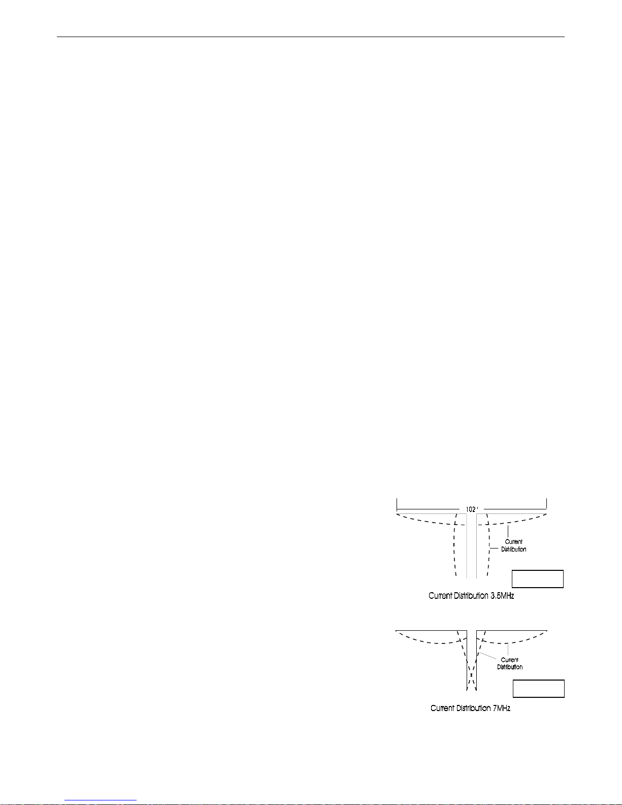
80 meter band:
On 80 meters the MFJ-1778 (G5RV) functions as a slightly short
half-wave dipole. The current distribution of the antenna and
matching line is shown in figure 1. The horizontal radiation
pattern is the same as a half-wave dipole on this band. With
horizontal polarization at heights below 100 feet the antenna is
practically omni-directional and has a high takeoff angle.
40 meter band:
On 40 meters the MFJ-1778 (G5RV) functions as "two halfwaves in-phase" fed with a quarter-wave impedance matching
transformer. The current distribution of the antenna and
transmission line impedance matching section is shown in figure
2. The horizontal radiation pattern is somewhat narrower than the
pattern of a half-wave dipole and is broadside to the radiator on
this band. The G5RV has a small amount of gain and radiates at
medium wave angles on 40 meters.
Figure 1
Figure 2
1
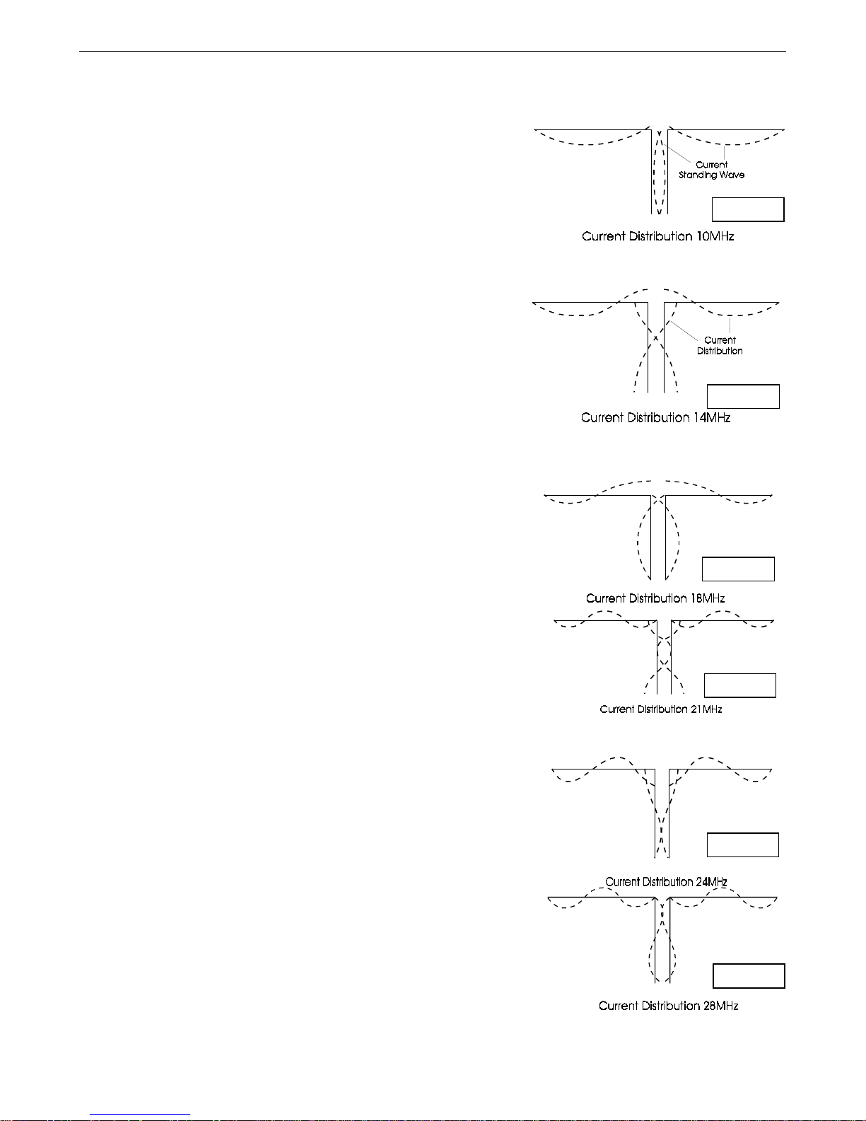
30 meter band:
On 30 meters the MFJ-1778 (G5RV) functions as an extended
double zepp. The current distribution of the antenna and
matching line is shown in figure 3. The horizontal radiation
pattern is similar to the pattern of the 40 meter band (broadside)
but has four additional minor lobes. The antenna has a gain of
around 3 dB on 30 meters.
20 meter band:
This is the true design frequency of the MFJ-1778. The
antenna is a 3/2 wave center-fed antenna and has a multi-lobe
pattern on this band. On this band the G5RV is a good DX
antenna at heights of 30-60 feet. The radiation angle is fairly
low. The feedpoint of the antenna is approximately 100 ohms
resistive, and the ladder line functions as a 1:1 ratio
transformer. See figure 4 for a digram of current distribution.
MFJ-1778 G5RV Multiband Antenna
Figure 3
Figure 4
17 meter band:
The antenna is a pair of full-wave antennas fed in-phase on this
band. The radiation angle of the antenna is low with many
lobes in all directions. The current distribution of the antenna
and matching line is shown in figure 5.
15 meter band:
The antenna is a pair of 1.1 wavelength long wires fed in-phase on
this band. This pattern is multi-lobed in the horizontal plane with
a low radiation angle. The current distribution of the antenna and
matching line is shown in figure 6.
12 meter band:
On 12 meters this antenna is a pair of 1.3 wavelength longwires
fed in-phase. The feedpoint resistance is fairly low. The
radiation pattern has many lobes and a low radiation angle. The
current distribution of the antenna and ladder line is shown in
figure 7.
10 meter band:
The MFJ-1778 functions as two 3/2 wave longwire antennas fed
in-phase on this band. The pattern has multiple lobes in all
directions. The current distribution of the antenna and matching
line is shown in figure 8.
Figure 5
Figure 6
Figure 7
Figure 8
2
 Loading...