

MFJ MFJ-1622 Instruction Manual
MFJ-1622 Instruction Manual Window Mount Antenna
1
MFJ-1622 Window Mount Antenna
Introduction
The MFJ-1622 Antenna was designed to provide portable or permanent HF communications on
40 through 10 meters and VHF on 6 and 2 meters. The universal mount design allows the user to
install the antenna in many ways. The mount will easily attach to window frames, balconies, and
railings. The MFJ-1622 works well indoors mounted to a desk or table as well.
The antenna consists of a collapsible whip, loading coil assembly, universal mount, counterpoise
wire, and choke. The operating frequency is adjusted by moving the tap on the coil. The
counterpoise wire length is adjusted for minimum SWR. The MFJ-1622 Antenna will allow the
operator to get on the air from locations where antenna size is limited.
Choosing a Mounting Position
WARNING: ALWAYS ATTACH THE SAFETY ROPE TO A STABLE SUPPORT
BEFORE ATTEMPTING TO ATTACH THE UNIVERSAL MOUNT TO A
WINDOW FRAME OR RAIL. INJURY AND DAMAGE COULD OCCUR
IF THE ANTENNA WERE TO FALL.
The design of the antenna allows it to be installed in many ways. It can be easily attached to a
window frame, window box or balcony railing. A Wooden fence is another common mounting
location.
The best performance will be obtained by placing the antenna outside, however the antenna may
be used indoors if necessary. The base plate may be attached to a table, book shelf, or other
suitable support. The counterpoise is simply placed on the floor. Some installations may require
the use of a C-clamp or vice-grips to secure the base plate. Always remember to keep the
antenna away from metal objects and out of reach to prevent injury.
WARNING: SERIOUS RF BURNS AND INJURY CAN OCCUR IF CONTACT IS
MADE WITH THE ANTENNA.
Parts List
[ ] Antenna Whip
[ ] Loading Coil Assembly
[ ] 50 feet of RG58 Coax
[ ] 35 feet of counterpoise wire
Tools Needed
[ ] #1 Flat Head Screwdriver
[ ] #2 Flat Head Screwdriver
[ ] Measuring Tape
[ ] 12mm or equivalent wrench
[ ] Mounting Bracket/Base Plate
[ ] Spacer
[ ] 2 feet of Safety Rope
[ ] _” x 3 _” bolts
[ ] _” – 24 split lock washer

MFJ-1622 Instruction Manual Window Mount Antenna
2
[ ] 3 Plastic wire ties
MFJ-1622 Instruction Manual Window Mount Antenna
3
Assembly
[ ] 1. Remove all Parts from the packing material. Check to see that all are present using the list
on page 1.
[ ] 2. Place the _”- 24 split lock washer onto the threaded end of the whip.
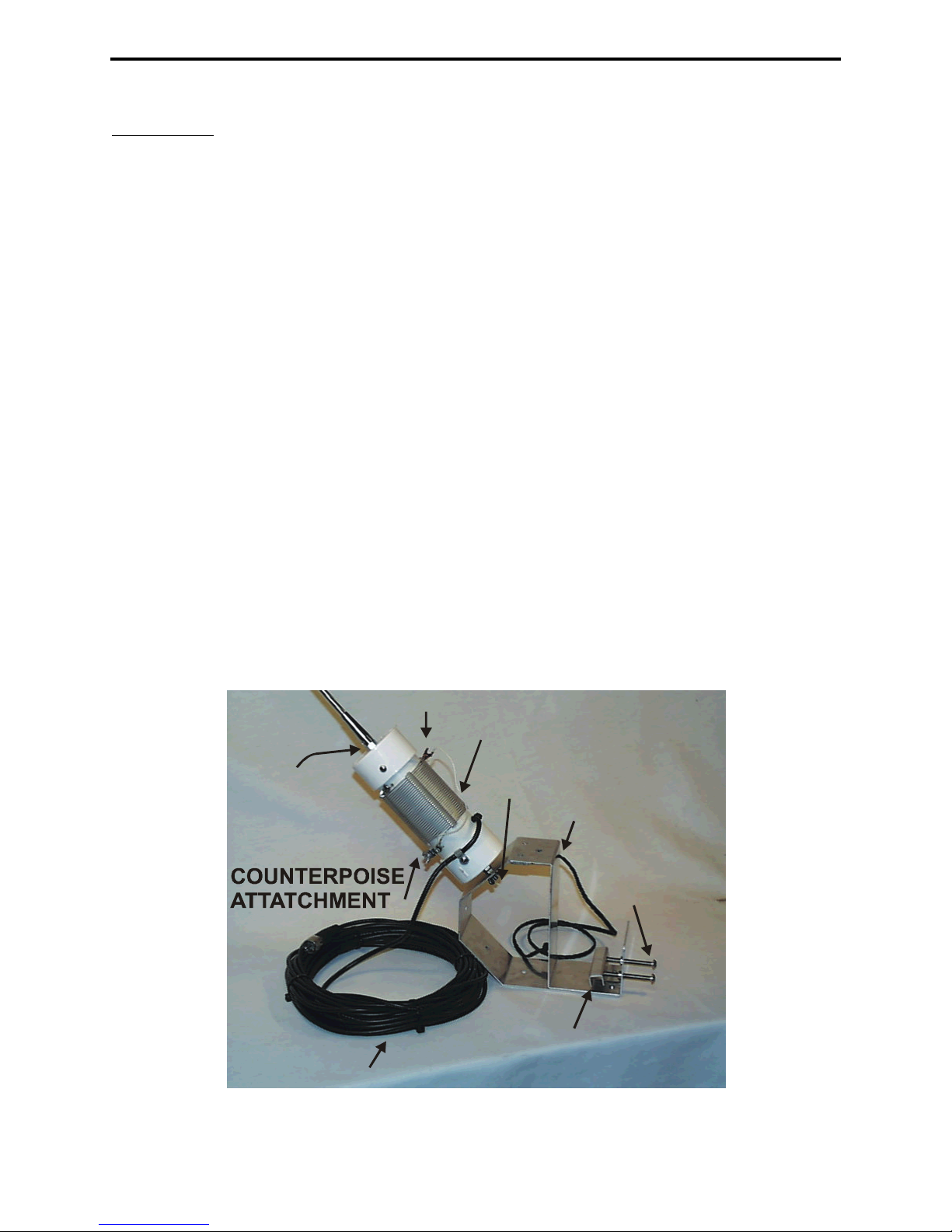
[ ] 3. Screw the antenna into the coupling nut (shown in Figure 1) located on top of the coil
assembly.
[ ] 4. Secure the antenna into the coupling nut using a 12mm wrench.
[ ] 5. Uncoil the coax cable to its full length.
[ ] 6. Measure 30 feet from the antenna end of the coax and mark this point with a piece of
tape.
[ ] 7. Begin 18 inches from the antenna winding the coax in a circle, 8-10 inches in diameter,
using the 30 feet measured in the previous step.
[ ] 8. Use the three black wire ties supplied to tie the choke coils together. Space the ties out
evenly around the circle. Figure 1 shows a picture of the finished choke.
[ ] 9. Insert the _” x 3 _” bolts into the threaded holes on the base plate approximately one
inch as shown in Figure 1.
[ ] 10. Place the spacer plate onto the bolts as indicated in Figure 1.
[ ] 11. Push one end of the safety rope through the rope hole as indicated in Figure 1. Tie a knot
on both ends of the rope to secure it.
ANTENNA
COUPLING
NUT
CHOKE
TAP
LOADING COIL
SAFETY ROPE
SPACER
SCREWS
WING NUT
Figure 1
 Loading...