

Page 1
MFJ
VHF/UHF Base Station Antenna
Instruction Manual
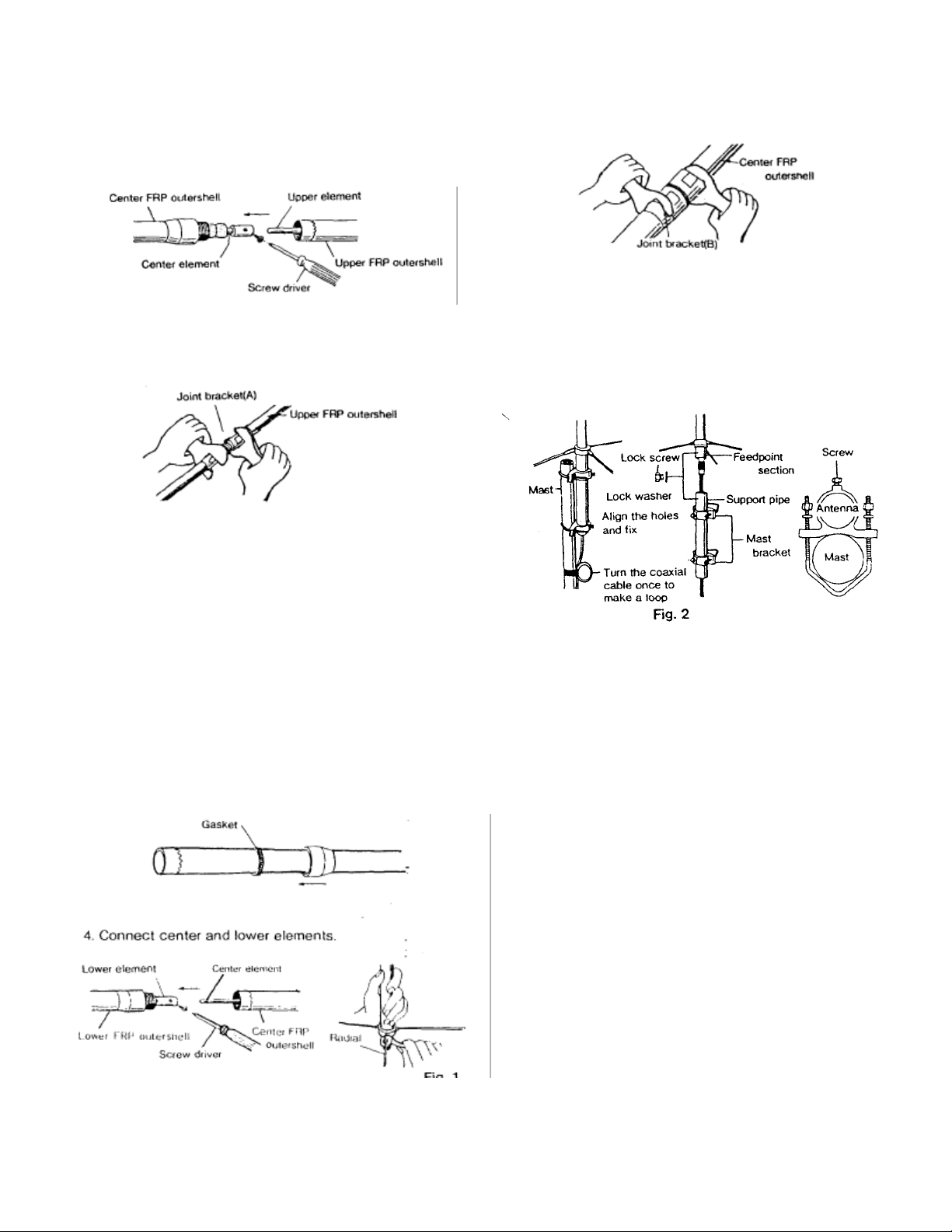
2. After connecting these elements with a screw, push back center
r
outershells. Then connect upper and center outershells at upper
Note: Be sure to fasten the bracket firmly, otherwise it may lead
joint
and
gasket holders have to be fixed at 10cm from the edge of FRP
1. Connect upper and center elements. To pull out element joint bracket
at the top of center element, make upper part of the element
down and shake lightly.
Note: Be sure to assemble the antenna from upper element. If the
antenna is being assembled from lower element, the element can not
be pulled out from outershell and fasten properly.
element downward in advance to connect upper and cente
no gap between each part.
Note: Be sure to fasten the bracket firmly, otherwise it may lead water
leakage problem.
6. Attach three radial elements as shown in Fig. 1.
7. Attach two mast brackets on support pipe and fix them. Then
connect a coaxial cable. with a connector for the
to the feed point section through the pipe.
joint bracket section.
3. Fasten upper part of the joint bracket (A) with a special wrench
attached by holding lower part of the joint bracket (A) firmly
with the wrench. Use narrow gap section of the wrench to fasten
and hold each part of the bracket. For perfect waterproof, fasten
the bracket until there is no gap between each part.
water leakage problem. Adhesive NOTE seal is attached on the
bracket. Remove the seal before installing the antenna. Gasket
outershell.
Note ; Do not pull out lower element.
5. Fasten lower part of joint bracket (B) just as the same way as the
joint bracket (A) with a special wrench attached. Use wide gap
section of the wrench to fasten and hold each part of the bracket.
For perfect waterproof, fasten the bracket until there is
8. Fix support pipe and feedpoint section of the antenna with lock
screw by aligning the holes at the bottom of the section and
upper part of the pipe.
9. Attach assembled antenna on a mast by taking whole balance
into account as shown in Fig. 2. Turn the coaxial cable once to
make a loop at right below the antenna to escape excess load
from the cable.
Note: Though acceptable mast diameter is from 30mm (1.18"), it is
recommended to use large diameter mast as possible because the
antenna is relatively large.
Note
Though all this antenna employs DC ground structure, circuit
across center conductor section and ground section of the connector is
open (not conducted) if it is measured by a volthom meter. If it is closed
(conducted), check to see coaxial cable and/or connector thoroughly.
Be sure to install the antenna vertically. Full performance of the
antenna can not be guaranteed if the antenna is not installed vertically.
Since connector is relatively complicated compared with conventional
type connector, utmost care has to be taken to handle connector to
coaxial cable connection. It is recommended to practice test
transmission for adjustment as short and least power as possible.
Warning
Do not touch or come close to the antenna during transmission. Do not
install the antenna where is easily reached by the children.
 Loading...