

Page 1

SOFTWARE CONSIDERATIONS
SHAREWARE
The CD shipped with the MFJ-1279/1279M/1279T contains shareware. This CD will automatically run
the MFJ Sound Card Interface Software Installation Menu upon startup. If the CD does not automatically
run in your system, you can manually start the installation menu. To do this, follow the steps listed below:
1. With the Shareware CD in the CD drive, click on the Start button at the bottom left of the screen.
2. Click on RUN. This will bring up a command window.
3. Click the Browse button.
4. When the browse window is open, double click on the CD drive.
5. Double click on the autorun.exe program.
6. The autorun.exe program will now appear in the command window.
7. Click OK, and the MFJ Sound Card Interface Software Installation Menu will begin to run.
From the menu, you may choose any shareware program(s) you wish to install. Though effective, this
software is limited in its uses. To get the full experience with your unit, MFJ recommends that you
purchase either the MFJ-1296 or the MFJ-1298 Sound Card Program.
The sound card programs on the provided CD are as we said before, “SHAREWARE”. If there are
problems with the software, then you need to contact the author of the program that you are trying to use.
MFJ Enterprises provides only limited support for these shareware programs.
MFJ-1296 & MFJ-1298 SOFTWARE PACKAGES
The MFJ-1296, RadioCom4, and the MFJ-1298, RadioCom5, are the best programs for soundcard
interfaces and amateur radio.
Some features of the MFJ-1296 and the MFJ-1298 include:
• PSK: Supports PSK-31, Q and B PSK
• SSTV: 32-bit color, supports all SSTV formats, screen sizes/SSTV parameters are all variable.
• FAX: Supports AM/FM bands. Includes Weather FAX and satellite FAX direct. Supports
ICO 267, 288, 352, and 567. RPM 48, 60, 90, 120, 180, and 240. FAX resolution is up
to 1810 dpi, FAX features IOC and slant-correction. FAX pictures can be saved,
printed, retransmitted.
• CW: Features automatic speed tracking, DSP notch and bandpass filters.
• RTTY: Supports all standard shifts and speeds. X/Y scope and frequency spectrum display
makes tuning RTTY a breeze. Also supports NAVTEX, European SYNOP, Baudot,
and Sitor-B.
• Radio control for over 80 radios.
• DSP Audio Filters and Analyzer.
• RS-232 Level Converter.
The MFJ-1298 has additional features that include Spectrum Analyzer, Dual Scope Display, Sound
Recorder, Time/Frequency Management, Frequency Analyzer, 3-D Scanner, Satellite Tracking, and much
more!
The MFJ RadioCom requires a computer with a minimum 200 MHz, Pentium/Celeron processor, at least
64 MB of RAM, and Win95/98/ME/2000/NT/XP operating system.
These fully integrated software packages can be purchased from MFJ and are fully supported by MFJ.
Page 2

MFJ-1279/1279M/1279T Instruction Manual Deluxe Sound Card Radio Interface
TABLE OF CONTENTS
Introduction ...........................................................................................................................2
1.0 Powering the MFJ-1279/1279M/1279T..............................................................................3
2.0 Connecting the MFJ-1279/1279M/1279T........................................................................... 3
3.0 MFJ-1279T Special Instructions........................................................................................ 4
4.0 Microphone and Radio Connections (MFJ-1279/1279M) ..................................................5
4.1 Internal Header and Jumper Connection Description............................................5
4.2 Jumper Diagrams (MFJ-1279/1279M)................................................................... 6
4.3 Customizing Internal Jumpers (MFJ-1279/1279M)................................................9
4.4 RS-232 Input Jumpers (JMP3, JMP4, JMP5) ........................................................10
4.5 Audio Termination Jumpers (JMP1, JMP2).......................................................... 11
5.0 Rear Panel Connections.................................................................................................... 11
5.1 Computer RS-232 port.........................................................................................11
5.2 CW Port...............................................................................................................11
5.3 Radio ................................................................................................................... 11
5.4 Auxiliary Audio Input.......................................................................................... 12
5.5 Computer.............................................................................................................12
5.6 GND.....................................................................................................................12
6.0 Operating Suggestions...................................................................................................... 12
6.1 Placement of this Unit ..........................................................................................12
6.2 Hum, Squeals, and Distortion...............................................................................12
6.3 Operating Adjustments.........................................................................................13
6.4 Monitoring Receiver (SSTV, Voice Keyer) ..........................................................14
7.0 Software...........................................................................................................................14
8.0 Troubleshooting Guide.....................................................................................................15
9.0 Technical Assistance.........................................................................................................16
10.0 Schematic Page 1............................................................................................................ 17
10.0 Schematic Page 2............................................................................................................ 18
1
Page 3

MFJ-1279/1279M/1279T Instruction Manual Deluxe Sound Card Radio Interface
INTRODUCTION
Thank you for purchasing the MFJ-1279/1279M/1279T Deluxe Sound Card Radio Interface. The MFJ1279/1279M1279T was designed for use in all sound card to radio applications. Great care was taken to
make sure hum, noise, and distortion are minimized or eliminated, insuring the best possible signal from
your equipment.
Before attempting to use the MFJ-1279T, please read section 3.0. Before attempting to use the MFJ1279/1279M, please read section 4.0. This section contains important information about interfacing the
MFJ-1279/1279M with your transceiver. We will start with a brief introduction into the special features
that make your Deluxe Sound Card Radio Interface an important addition to any Amateur station with a
computer.
MFJ-1279/1279M/1279T Features:
Computer RS-232 Port: This port allows the computer to control the push-to-talk of your radio and the
microphone push-to-talk switch to override and/or interrupt your computer’s transmission.
CW Output: Allows direct computer keying of radios operating in CW or FSK operation.
Microphone/Radio plug-in jumpers: Internal jumpers program microphone wiring for any brand or
model of radio with the appropriate 8-pin connector. There is no need to solder tiny plugs and wires or
purchase adapters.
PTT Message Interrupt/Stop: Microphone PTT (push-to-talk) switch automatically halts outgoing
messages when using software that allows external com-port interrupts. Even if software does not allow
interrupts, you can still hold the microphone PTT to stop digital transmissions and transmit microphone
audio.
Footswitch: A footswitch can be used for PTT when VOX is not used.
Radio/Speaker-Computer/Speaker switching: Transfers audio lines with a touch of the ON/BYPASS
switch. No need to move cables every time you change use of the computer or radio. NOTE: Requires
use of an external speaker for radio.
Off-Air Recording: Capture signals from your receiver's audio jack for review or replay, or use with
spectrum analyzer programs.
RFI Proof Circuitry: RF suppression and line isolation virtually eliminates RF feedback, hum, and
distortion. Multiple isolation transformers prevent audio ground loops when receiving or transmitting.
Level controls: Two level controls, one for transmitter drive and one for receiver -to-sound card drive
level. No need to adjust microphone gain or sound card level settings every time modes are changed.
Stereo or Mono Audio input: A front-panel switch allows left, right, or both sound card audio output
channels to drive transmitter.
Headphones: A front-panel standard ¼” phone jack allows use of headphones and automatically
disables the external radio speaker.
Rugged Construction: A solid all-aluminum cabinet and sturdy surface-mount construction gives the
MFJ-1279/1279M/1279T mechanical and electrical durability.
2
Page 4
MFJ-1279/1279M/1279T Instruction Manual Deluxe Sound Card Radio Interface
1.0 POWERING THE MFJ-1279/1279M/1279T
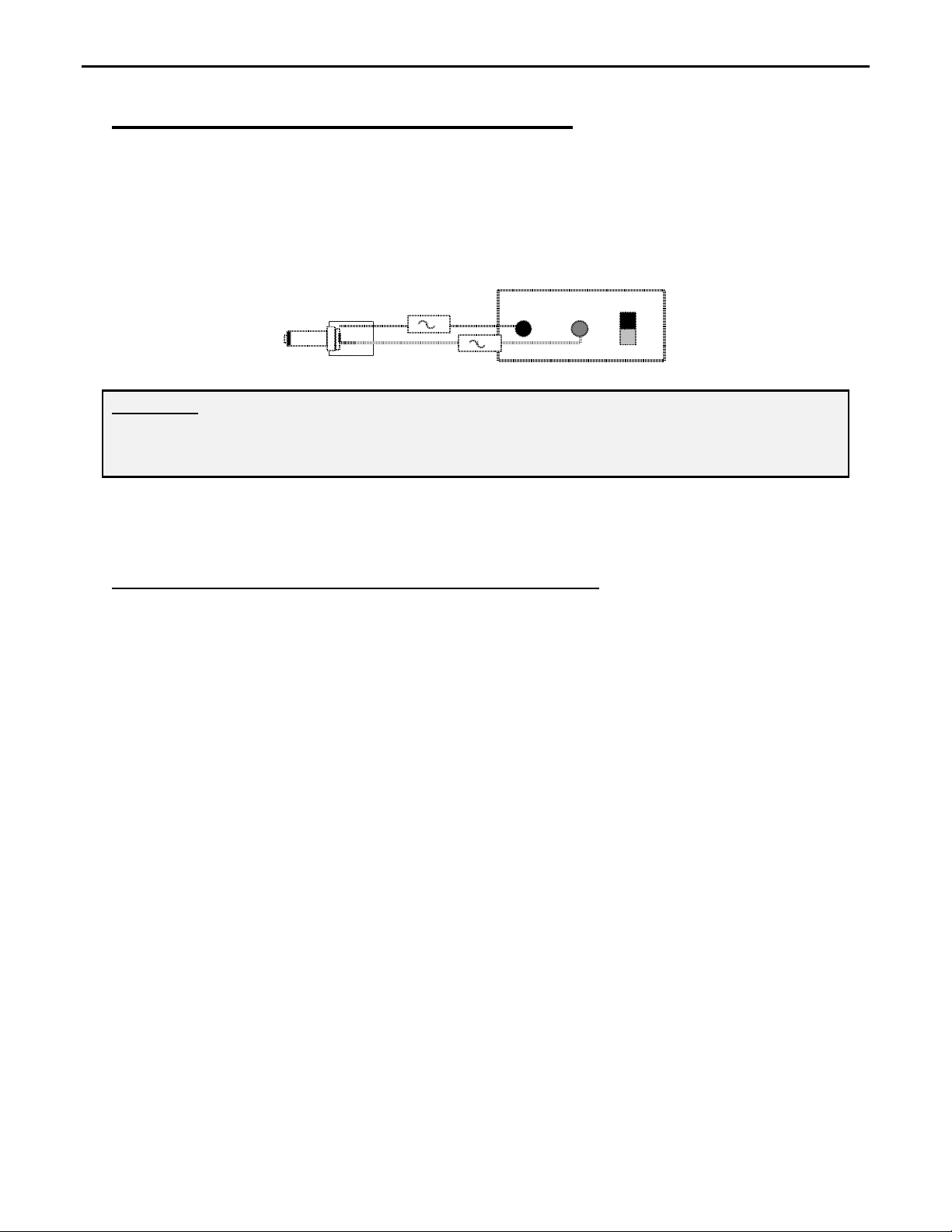
External Power: Power the MFJ-1279/1279M/1279T with any well-filtered power source capable of
supplying 12-15 Vdc at 100 mA. The minimum operating voltage is 10 Vdc.
The Sound Card Radio Interface external power jack accepts a standard 2.1mm coaxial power plug. The
power plug's center pin must be positive (+) and ground-isolated. The outer shell is negative (-) and may
be grounded or floated at the supply. When connecting to a high current supply (more than one ampere),
we strongly recommend fuse protecting both positive and negative supply leads with ½ ampere to 1
ampere fast-blow fuses.
1-A
-
1-A
-
+
Power Supply+
WARNING: Never insert the power plug with power applied—an accidental short from (+) to
chassis ground may result. Also, never allow the MFJ-1279/1279M/1279T supply
voltage to exceed 16 Vdc. Connections to high current power sources must be fuse
protected!
MFJ-1312D Power Supply: The MFJ-1312D wall adapter is also suitable for powering your Sound
Card Radio Interface. It comes with the correct 2.1mm power plug installed, and is available directly
from MFJ Enterprises, Inc. or through your local MFJ dealer.
2.0 CONNECTING THE MFJ-1279/1279M/1279T
FRONT PANEL:
HEADPHONES Accepts a standard ¼” monaural or stereo plug for headphones.
Inserting plug automatically disables the radio’s external speaker
MICROPHONE Accepts standard 8-pin microphone plug (8-pin modular for the
MFJ-1279M) (4-pin for the MFJ-1279T)
INPUT
Selects left, both, or right sound card audio channels to drive
transmitter
MANUAL/VOX
Selects PTT control from COM port or transmitter VOX operation
MONITOR/OFF Allows the user to hear signals through the radio speakers or
headphones while audio is simultaneously routed through the
Sound Card Radio Interface
ON/BYPASS Selects computer audio and control (ON) or independent operation
of computer and radio (BYPASS)
XMIT Illuminates when computer transmitting or when ready to transmit
(VOX) with audio input
PWR Illuminates when MFJ-1279\1279M/1279T power is connected
and unit is ON
FOOTSWITCH Accepts standard ¼”mono plug allowing footswitch control of
PTT when VOX is not used.
3
Page 5

MFJ-1279/1279M/1279T Instruction Manual Deluxe Sound Card Radio Interface
REAR PANEL:
POWER
Requires 12-15 Vdc @ 100mA (16 volt absolute maximum)
COMPUTER
RS-232
CW OUTPUT
DB-9 female serial (COM port) connection
RCA phono jack connects to the KEY jack of radio
RADIO
TO EXT SPKR 3.5mm mono jack connects to station loudspeaker or other audio
accessories normally connected to radio speaker jack
FROM AUDIO OUT
AUX AUDIO INPUT
3.5mm mono jack connects to external speaker output of radio
3.5mm stereo jack for connections to an external audio device
(audio routed directly to computer’s sound card input when MFJ1279/1279M/1279T is bypassed)
COMPUTER
TO SOUND CARD
AUDIO IN
TO EXT SPKR
FROM SOUND
CARD AUDIO OUT
3.5mm stereo jack connects to computer sound card input
3.5mm stereo jack connects to computer speaker
3.5mm stereo jack connects to computer sound card output
GROUND
Ground terminal to station's ground buss (see section 5.6)
3.0 MFJ-1279T SPECIAL INSTRUCTIONS
The MFJ-1279T is a special interface unit modified for use with Ten-Tec and other radios using four-pin
microphone connectors. Most four-pin connector systems use the microphone shield as a ground return
for push-to-talk lines.
Use of audio shields as a control or PTT grounds causes audio systems to be much more susceptible to
ground loop hum and noise, that is why most modern radios maintain separate PTT and audio ground
leads. When using a common audio and PTT ground, we must be much more careful with external
connections.
Please follow these basic system guidelines:
1.) Always ground the rear cabinet ground lug of the MFJ-1279T directly to the radio’s rear- chassis
ground. This will allow control signals and any undesired hum or noise to flow through the rear
panel chassis ground connection and reduce hum and noise in the audio connections.
2.) Never make any ground connection at HD1 in the MFJ-1279T. This will force any control
system grounds to use the rear panel chassis ground connections, keeping the microphone shield
clear of any unwanted hum and noise.
3.) Always connect the computer and radio AC power cords to the same outlet or outlet strip. This
will minimize voltage differences between the computer and radio chassis, reducing unwanted
ground loop currents.
4
Page 6
MFJ-1279/1279M/1279T Instruction Manual Deluxe Sound Card Radio Interface
4.) Locate the MFJ-1279T near the radio. This will allow use of shorter ground connections and
shorter microphone cords, reducing the resistance of the audio system shields.
5.) Ground the computer to the station ground buss if possible. This will ensure computer cabinets
and radio cabinets are all at the same potential, and reduce unwanted hum and noise.
Ten-Tec
and
KENWOOD 4-Pin Microphone Setup: TS-120S, 130S, 180S, 511S, 520S, 530, 600, 700
TS-820, 830, TR-7200A, 7400A, 7500
This diagram may cover some other
radios in the KENWOOD product line
with 4-pin round microphone jack.
If there are any Questions concerning
the information provided, please refer
to your RADIO NSTRUCTION
MANUAL.
MFJ is neither liable nor responsible
for any mistakes or errors in the
information provided.
Receive Audio is taken from the
External Speaker output or some other
speaker level audio source.
Special Notes for Ten-Tec Radios:
When using Ten-Tec radios, avoid using the station’s 13.8-volt dc power source to power the MFJ-1275T
Sound Card Interface. Always use the MFJ-1312D, or equivalent power adaptor!
4.0 MICROPHONE AND RADIO CONNECTIONS (MFJ-1279/1279M)
Different manufacturers and different radios may wire the same style connectors differently. The MFJ1279 and MFJ-1279M have internal headers that use small moveable jumpers. The MFJ-1279 uses
common round 8-pin microphone connectors found on most transceivers. The MFJ-1279M comes with a
modular microphone jack (like telephones might use). The MFJ-1279T uses a round 4-pin for Ten-Tec.
Internal jumpers are used to program connections for any radio that connects to the prewired connectors.
This feature eliminates the need for soldering jacks or purchasing adapter cables. The MFJ-1279/1279M
must be configured using the internal jumpers before use (see section 4.1 and 4.2).
The microphone/radio setup procedure requires a few minutes of time. Before you start, you will need
the manual of your radio readily available.
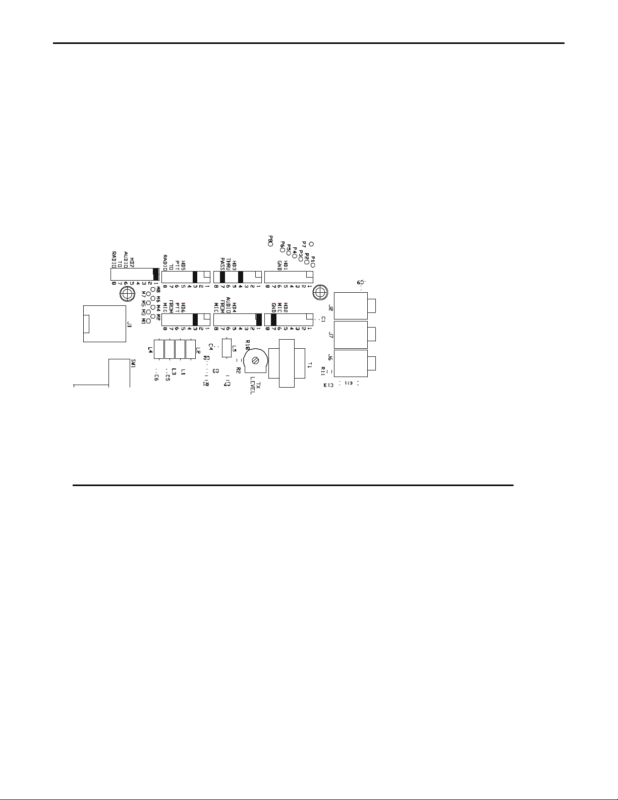
4.1 INTERNAL HEADER AND JUMPER CONNECTION DESCRIPTION
This section is for the MFJ-1279 and MFJ-1279M only. If you have a MFJ-1279T be sure to read
section 3.0. The jumpers in this unit are grouped by connection type, with all eight microphone pins in a
row. The connection blocks are:
HD1 Chassis ground
HD2 Audio ground (NOT the same as chassis ground)
5
Page 7

MFJ-1279/1279M/1279T Instruction Manual Deluxe Sound Card Radio Interface
HD3 Pass through, jumper all connections except microphone audio (HD4, HD7) and push-to-talk
lines (HD5, HD6)
HD4 Audio from microphone
HD5 PTT line to radio
HD6 PTT from microphone
HD7 Microphone audio output to radio
There are eight rows of jumpers (16 pins) in each header. Each pin, starting from the rear of the unit,
represents pins one through eight of the microphone connectors.
HD1- This header allows connections to chassis ground. The chassis ground is normally not
connected to any audio ground, except in the radio itself. It is normally used only for control
connections, like PTT or “up-down” button grounds.
Note: If chassis ground connects to microphone audio grounds outside the radio, low-level
audio hum or distortion may appear on the transmitted signal.
HD2- This header connects to the microphone audio ground. The pin selected here should match the
microphone audio ground lead. This ground is normally not connected to any chassis ground.
Note: If the audio ground connects to any chassis outside the radio, transmitter audio hum or
distortion may occur.
HD3- This header provides a straight-through connection. It normally has jumpers in all positions
except leads used by microphone “hot” audio (HD4, HD7) and push-to-talk lines (HD5, HD6).
Microphone ground leads (PTT and audio grounds) should be jumpered at this header even when
jumpered at HD1 or HD2.
HD4- This header is for the microphone’s hot audio output. This jumper pin should also match the
radio’s “hot” audio input lead from the microphone. The pin jumpered should match the selection at
HD7. This jumper pin number should not be connected at HD3.
HD5- This header is for the radio’s PTT (push-to-talk) lead. This jumper should match the radio’s hot
PTT lead. The jumper selected here should also match the jumper selection at HD6. This pin number
should not have a pass-through connection at HD3.
HD6- This header is for the microphone’s PTT (push-to-talk) input lead. The jumper should match the
microphone’s “hot” PTT lead. The pin selected here should also match the selection at HD5 only.
HD7- This header is for the hot audio lead to the radio. The jumper setting should match the jumper
setting at HD4 only.
4. 2 JUMPER DIAGRAMS (MFJ-1279/1279M)
The Jumper Installation diagrams with this instruction manual will help you in setting up your MFJ1279/1279M to match your radio. If your radio is not listed with the diagram, it means that we have not
verified your radio to use that diagram. You can try to install jumpers as indicated. If that does not work,
please refer to the radio manual to identify the MIC pin assignment for you radio, then follow the
instructions given in the MFJ-1279/1279M instruction manual to install the jumpers.
Begin by removing the screws from the sides of the cabinet. Lift the cover off. Look from the top rightside view. Observe the groups of pins between the microphone connector and the microphone output
wire. Notice the pins start at the back and are labeled 1 through 8 before repeating at the next header
group.
If your radio is listed, place jumpers at pins shown in the following diagrams:
6
Page 8

MFJ-1279/1279M/1279T Instruction Manual Deluxe Sound Card Radio Interface
ICOM 8-Pin Round Microphone Setup:
IC-255, 288, 28, 290, 38A, 375, 707, 718, 725, 726, 728, 729, 730, 735, 737, 745, 746, 746PRO, 751
IC-756, 756PRO, 756PROII, 775DSP, 761, 78, 781, 910H
This diagram may work with other radios in
the ICOM product line using the 8-pin round
microphone connector.
For radios that are not listed, please refer to
your RADIO INSTRUCTION MANUAL and
section 4.3 of this manual.
MFJ is neither liable nor responsible for any
mistakes or errors in the information provided.
Receive Audio is taken from the External
Speaker output or some other speaker level
audio source.
ICOM 8-Pin Modular Microphone Setup:
IC-207H, 2720H, 2800H, 703, 706, 706MKII, 706MKIIG, V8000
This diagram may work with other radios in
the ICOM product line using 8-pin modular
microphone connector.
For radios that are not listed, please refer to
your RADIO INSTRUCTION MANUAL and
section 4.3 of this manual.
MFJ is neither liable nor responsible for any
mistakes or errors in the information provided.
Receive Audio is taken from the External
Speaker output or some other speaker level
audio source.
YAESU FT-650, 700, 707, 712, 726, 736, 756, 767, 77, 790II, 840, 890, 990, 1000D Series
This diagram may work with other radios in the
Yaesu product line using 8-pin round
microphone connector.
For radios that are not listed, please refer to your
RADIO INSTRUCTION MANUAL and section
4.3 of this manual.
MFJ is neither liable nor responsible for
any mistakes or errors in the information
provided.
Receive Audio is taken from the External
Speaker output or some other speaker level audio
source.
7
Page 9

MFJ-1279/1279M/1279T Instruction Manual Deluxe Sound Card Radio Interface
YAESU 8-Pin Modular Microphone Setup:
FT-817
This diagram may cover the radios in the
Yaesu product line using the 8-pin modular
microphone connectors.
For radios that are not listed, please refer to
your RADIO INSTRUCTION MANUAL and
section 4.3 of this manual.
MFJ is neither liable nor responsible for any
mistakes or errors in the information provided.
Receive Audio is taken form the External
Speaker output or some other speaker level
audio source.
KENWOOD 8-Pin Round Microphone Setup:
TS-50, 140, 430, 440, 450, 570, 660, 670, 680, 690, 701, 711, 780, 811, 850, 870, 930, 940, 950
TR-50, 751, 851, 3200, TM-201A, 201B, 211, 221, 231, 241, 321, 331, 401A, 401B, 421, 431,
441, 521, 531, 541, 621, 631, 701, 721, 731, 2530, 2550, 2570, TW-4000, 4100
This diagram may cover other radios in the
Kenwood product line using the 8-pin round
microphone connector.
For radios that are not listed, please refer to
your RADIO INSTRUCTION MANUAL and
section 4.3 of this manual.
MFJ is neither liable nor responsible for any
mistakes or errors in the information provided.
Receive Audio is taken from the External
Speaker output or some other speaker level
audio source.
KENWOOD 8-Pin Modular Microphone Setup:
TM-251, 255, 261, 451, 461, 641, 642, 732, 733, 741, 742, 941, 942, G707, V7A
This diagram may cover other radios in the
Kenwood product line using the 8-pin modular
microphone connector.
If there are any Questions concerning the
information provided, please refer to your
RADIO INSTRUCTION MANUAL.
MFJ is neither liable nor responsible for any
mistakes or errors in the information provided.
Receive Audio is taken from the External
Speaker output or some other speaker level
audio source.
8
Page 10

MFJ-1279/1279M/1279T Instruction Manual Deluxe Sound Card Radio Interface
Yaesu Mic Jack Pin-out, Front View
4.3 CUSTOMIZING INTERNAL JUMPERS (MFJ-1279/1279M)
The section is for the MFJ-1279 and MFJ-1279M only. If your radio is not listed above, you can
create a custom jumper position table.
Begin by removing the screws from the sides of the cabinet. Lift the cover off. Look from the front view
and notice the group of pins and black jumpers on the left side behind the microphone connector and in
front of the microphone output wire. Notice the pins start at the rear and are labeled 1 through 8 before
repeating at the next header group.
Fill in a custom table like the following:
Table 1. Yaesu FT-1000 series
Pin HD1 gnd
for PTT
HD2 gnd
for MIC
HD3 pass HD4 aud
MIC
HD5 PTT
Radio
HD6 PTT
MIC
HD7 aud
Radio
1 X
2 X
3 X
4 X
5 X X
6 X X
7 X X
8 X X
To make a jumper table for an unlisted radio, you must look at the radio manual. Find the page that shows
the microphone wiring. This is a sample of a Yaesu-style wiring diagram that was used above:
Mic
Mic Gnd
7
8
6
PTT
5
PTT Gnd
If you compare table 1 to this connector diagram, you will see how it is laid out. Notice an “X” was
placed at the appropriate PTT and MIC pins according to the rules below.
Look at the microphone-wiring diagram in your radio manual, fill in a table, and connect the leads as we
have done in our example. We have provided a blank chart below for you to fill in.
1.) Header 4 and 7 should copy each other, and use the same jumper pin number for the center
MIC wire.
2.) Header 5 and 6 also jointly share the same pin numbers as the PTT pin.
3.) The MIC GND, HD2, should connect to the same pin as the outer MIC lead and only that
pin.
4.) The GND, HD1, should connect to the PTT ground pin.
5.) Be sure to place a pass-through connection jumper on every lead EXCEPT numbers used
on HD 4, 7, 5, and 6.
9
Page 11

MFJ-1279/1279M/1279T Instruction Manual Deluxe Sound Card Radio Interface
The following blank table is for your personal use. Use your radio’s manual to complete the table. This
will assist you in properly setting the jumpers for your radio.
Remember!!! Use the following wiring chart rules:
1.) Never ground the microphone audio ground to the chassis ground!
2.) HD4 and HD7 are always the same jumper slot number
3.) HD5 and HD6 are always the same jumper slot number
4.) HD3 always has a jumper except where HD4 through HD7 are jumpered!
Pin HD1 gnd
for PTT
1
2
3
4
5
6
7
8
HD2 gnd
for MIC
HD3 pass HD4 aud
MIC
HD5 PTT
Radio
HD6 PTT
MIC
HD7 aud
Radio
4.4 RS-232 INPUT JUMPERS (JMP3, JMP4, JMP5)
There are three headers and near three LED’s in the right rear area (viewed from front panel area) of the
circuit board, near the RS-232 computer connection. Each LED will light when the computer sends a
control signal on the COM port for each LED. From left to right, the LED’s are for the RTS, TXD, and
DTR lines. From left to right, each header in front of the LED’s is for RTS, TXD, and DTR signals.
With or without jumpers installed, if you transmit with software, you will see one or more LED’s light.
This tells you the computer is sending a good control signal, and it tells you what line is carrying the
signal.
Installing a jumper towards the two pins (pins 1 and 2) near each LED, will activate the CW OUTPUT
from the selected LED. Installing a jumper towards the front panel (pins 2 and 3) will activate the PTT
(push-to-talk) system from the selected LED.
For example, if you want to send CW, bring up a CW program. Start sending a test text, and look for the
flashing LED. Assume it is the middle LED, TXD. Jumper JMP4 should be positioned between pins 1
and 2, and the CW Output will key the radio.
Assume you enable the TX on a PSK program. If you see DTR light (the LED on the far right), you can
jumper JMP5 between pins 2 and 3. This will allow the control line to enable the PTT function when
DTR is active.
10
Page 12

MFJ-1279/1279M/1279T Instruction Manual Deluxe Sound Card Radio Interface
4.5 AUDIO TERMINATION JUMPERS (JMP1, JMP2)
JMP1 and JMP2 are located just behind the MAN/VOX switch. JMP1 and JMP2 connect a 10-ohm load
resistor across the computer sound card output to simulate a speaker load. While a load is normally not
necessary, it may be needed if the sound card has excessive output level or is unstable without a load.
Remember installing these jumpers will reduce sound card level when transmitting but it may, at times,
reduce distortion and noise. It will not affect any other function.
5.0 REAR PANEL CONNECTIONS
The rear panel has one power jack, one RS-232 port, one CW output jack, six audio jacks, and a ground.
The use of each connection is described below.
5.1 COMPUTER RS-232 PORT
The COMPUTER RS-232 port is a standard female DB-9 connector. It should connect to an active COM
port on your computer. This connection allows the computer to watch the PTT line from your
microphone, and the computer to control the transmitter PTT line. You must normally enable the COM
port you use (normally COM1 or COM2) in the software you are using. Check the help menu of the
program for help with COM port settings. See section 4.4 for configuring RS232 port jumpers.
5.2 CW PORT
The CW PORT is a standard RCA phono jack. It should connect to the KEY jack of the radio. This
connection allows direct computer keying of your radio in CW or FSK operation. See section 4.4 for
details on configuring the RS-232 port for direct CW keying.
5.3 RADIO
TO EXT SPKR: This 3.5mm monaural jack should be wired to the radio’s external speaker. This jack
connects the radio’s external speaker to the radio’s speaker output when the front panel ON/BYPASS
switch is in the “out” or BYPASS position. The MFJ-1279/1279M/1279T automatically disconnects the
radio’s speaker when the ON/BYPASS switch is “in” or ON, and the MONITOR switch is not pushed.
The MONITOR/OFF switch defeats the speaker switching, and causes the external speaker or
headphone jack to remain active when the MONITOR/OFF switch is “in” (MONITOR).
FROM AUDIO OUT: This 3.5mm monaural jack should connect to your radio’s external speaker
output jack. It connects directly to the radio “TO EXT SPKR” jack when the ON/BYPASS switch is
“out” (BYPASS) or when the MONITOR/OFF switch is “in” (MONITOR).
1. If only an internal radio speaker is used, you will have to plug, unplug or partially plug this
connection at the radio when changing between digital and standard operation. We recommend
using an external radio speaker to simplify changes between digital and standard operation.
2. If you wish to use a radio line-level audio output connection, you can connect the line-level
output to this jack. In this case, the MONITOR/OFF switch should be placed in the MONITOR
position. Otherwise, the radio may not have enough audio drive for the computer when receiving
digital transmissions.
Note: Always operate the receiver at normal listening volume before switching to digital
modes. Potentiometer R31 adjusts drive level from the radio receiver to the sound card.
R31 is the adjustable potentiometer closest to the right side (front view) of the unit. A
hole is provided in the cover so the pot can be adjusted without removing the cover. Use
a very small flat-blade screwdriver and be careful to not break the potentiometer!
11
Page 13

MFJ-1279/1279M/1279T Instruction Manual Deluxe Sound Card Radio Interface
5.4 AUXILIARY AUDIO INPUT
The AUX AUDIO INPUT is a 3.5mm stereo jack. This jack allows other external audio devices to
remain connected to the computer when not using digital modes. When the MFJ-1279/1279M/1279T is
“off” (BYPASS) the external device will be connected directly to the sound card input. This allows
changes in computer use without moving cables and wires.
5.5 COMPUTER
TO SOUND CARD AUDIO IN: This 3.5mm stereo jack connects to the sound card audio-input. You
can use either the sound card’s microphone or the line level input. This jack connects the radio’s audio
output to the computer’s audio input when the ON/BYPASS switch is ON. This jack connects to the
AUX AUDIO INPUT when the ON/BYPASS switch is “out” (BYPASS).
Note: If you use the microphone input, you will want to disable any extra gain provided by the
sound card. This function is normally available in the “Advanced” menu of sound card
“volume control” software.
TO EXT SPKR: This 3.5mm stereo jack connects to the computer’s external speaker system. This jack
is automatically connected to the computer’s audio output when the ON/BYPASS switch is “out”
(BYPASS). It is not connected when the ON/BYPASS switch is “in” (ON), disabling the computer
speakers.
FROM SOUND CARD AUDIO OUT: This 3.5mm stereo jack connects to the computer’s audio
output. This jack connects the computer audio output to the radio’s microphone input when the
ON/BYPASS switch is “in” (ON). It connects the computer to the “TO EXT SPKR” jack and the
computer’s speaker system when the ON/BYPASS switch is “out” (BYPASS). See section 4.5 for
termination of computer, if there are problems with squeals or abnormal modulation when the sound card
drives the transmitter.
5.6 GND
A ground connection post has been provided in case your station has RFI problems or audio hum. In
most cases, this connection is not necessary. If you notice hum or noise on any audio lines, try
connecting this post (with the shortest possible connection) to the ground post on your radio, station
ground, or computer.
6.0 OPERATING SUGGESTION
6.1 PLACEMENT OF THIS UNIT
We recommend placing this unit as close to the radio and computer as possible. Do not place this unit
within one foot of power transformers, video monitors, or any device that emits strong varying magnetic
fields. If you locate this unit near a monitor, the sweep circuits can introduce hum and noise into your
signal. If there is a powerline-operated transformer within several inches and if it has flux leakage, 60cycle hum can be introduced into your equipment.
6.2 HUM, SQUEALS, AND DISTORTION
The MFJ-1279/1279M/1279T is one of the best-designed digital interface products available. It includes
multiple isolation transformers for audio lines, independent chassis and signal grounds, RF bypassing,
and has no troublesome solid-state components in audio lines. Should a distortion, hum, or feedback
problem occur, it almost certainly will be from wiring or operational errors external to the MFJ1279/1279M/1279T.
12
Page 14

MFJ-1279/1279M/1279T Instruction Manual Deluxe Sound Card Radio Interface
When equipment is interconnected, ground loops can be created. A ground loop occurs when a modest
amount of AC or DC power flows between equipment grounds through cables that normally carry lowlevel signals, such as audio or microphone wiring. Unwanted hum, distortion, squeals, and/or erratic
operation may result. Power supply ground loops are often misdiagnosed as “RF feedback”.
To cure distortion, hum, or erratic operation it is often necessary to find the cause. To eliminate RF
feedback as a cause, replace the antenna with a dummy load. Ground the shield of the dummy load to the
normal antenna lead shield, so you do not disturb any possible ground paths. If the problem persists, it is
probably caused by a ground loop. If the problem disappears, it is almost certainly RF related. Be sure
your station ground is good, all the equipment is grounded together properly with a wide smooth
conductor, and you have followed all station wiring suggestions found in reliable sources such as the
ARRL Handbook.
If the problem occurs even while transmitting on a dummy load, the problem is almost certainly a ground
loop or wiring error. Be sure microphone wiring and jumpers are installed correctly, as outlined in
section 4 of this manual. Be sure microphone ground connections have continuity throughout the entire
system, and that the microphone ground is NOT connected to any other ground or chassis connection
outside of the radio.
Check the sound card volume control settings, and the gain settings of the radio. Be sure they are close to
normal operating settings, and not set too high. Be sure you have turned the radio’s monitor feature OFF
when working digital, to prevent audio from looping back through the computer.
For extreme problems and for improved lightning protect to your equipment, we have provided a ground
screw to allow grounding of our unit to the computer case, station ground, or radio ground. Some
manufactures actually think that NOT providing a ground connection is doing you a service, and tout the
lack of a ground as an advantage!
6.3 OPERATING ADJUSTMENTS
One of the most common problems using digital modes is improper system level. Even at best, digital
modes have limited dynamic range* compared to modes that closely “fit” filter bandwidths in the
transmitter and receiver. When the radio filter is wider than the mode being used, the system depends
heavily on having absolutely no distortion at any place in the system. Adjustments and levels throughout
the entire system affect bandwidth and quality of transmitted and received signals.
When transmitting, it is extremely important to use correct gain levels. If the input of a transceiver is
overdriven, the signal will contain unwanted products. Problems might not show on spectrum or IMD
displays and if they do, many people do not recognize them. Excessive level into the radio can aggravate
harmonic distortion (this often does not register on IMD or displays), causing transmissions on multiple
frequencies. For example a PSK transmitter using 1,000 Hertz offset will have some signal level at 2,000
Hertz and every other multiple of 1,000 Hertz. These harmonics might no make it back through a narrow
filter, and while they cause others interference they will not show on a spectrum display! The same is
true for poor carrier suppression. Since the carrier can be outside the passband of a receiver, it will not
always show on displays of people you are working.
*Dynamic range is the ratio of strongest undesired signal tolerated to weakest signal that can be copied.
Problems also occur when audio levels are too low. If audio level from the sound card or interface is too
low, the ratio of signal to hum and/or noise will also be reduced. The proper setting is generally one that
allows the microphone and receiver gain to be set at normal operating levels for SSB. Power is reduced
or adjusted by fine-tuning levels with the controls inside the MFJ-1279/1279M/1279T. The best way to
13
Page 15

MFJ-1279/1279M/1279T Instruction Manual Deluxe Sound Card Radio Interface
check for proper transmission is to listen to your own signal on a separate receiver. Use a narrow filter,
and take care to avoid overloading the receiver.
If you cannot listen through a separate receiver, the best general guideline is to use normal microphone
gain settings and approximately half volume on the sound card “Volume” settings. Adjust the transmitter
level control (R18) in the MFJ-1279/1279M/1279T for normal transmitter drive (just at the start of ALC
action) and use the microphone gain on the transmitter (or sound card volume) for fine adjustment. Use a
normal receiver volume setting, and adjust the sound card microphone level (make sure any extra gain
options are off) to approximately half scale. Adjust the receiver level control (R31) in the MFJ1279/1279M/1279T for normal display operation.
Regardless of what you do, it is always a good idea to have someone listen to your signal when the band
is empty, signals are strong, or noise is very low. They should look carefully for spurious signals, noise,
and hum.
When transmitting on modes like MFSK and PSK, always try to use a frequency setting of more than
1500 Hz and less than 2500 Hz. This will allow the transmitter’s SSB filter to suppress unwanted
harmonics from the audio system driving the transmitter.
If you use the line-level output of a radio, the receiver volume control generally has no effect on receiving
levels. Be sure you always leave the MONITOR/OFF switch in the MONITOR connector, when there is
no radio speaker plugged in, or when using a radio line output connection. As an alternative, you can
plug the line output of the radio directly into the computer soundcard.
Remember it is sometimes necessary to select the narrowest filter possible in the receiver, rather than
depending on the computer to filter out strong unwanted stations. If you depend only on the sound card,
you will find that even very clean strong signals overload your system. The problem is often in YOUR
receiver system, not in the offending transmitter. Many transceivers allow a selection of narrow filters
while operating SSB, or include passband-tuning controls. If you have trouble with a strong station
nearby causing interference, try using more selectivity or using the receiver’s notch filter to reduce the
signal level.
6.4 MONITORING RECEIVER (SSTV, VOICE KEYER)
Certain modes, such as SSTV and Voice Keying, occasionally require listening to receiver audio. We
have provided a front-panel MONITOR switch on the MFJ-1279/1279M/1279T front panel for this
purpose.
During SSTV or Voice Keyer operations, the MONITOR switch should be set to monitor (in). This will
allow you to hear receiver audio and see SSTV pictures at the same time.
The MONITOR switch will only operate if you have the external speaker connection of the radio
connected to the MFJ-1279/1279M/1279T RADIO From Audio Out connector. You must also use an
external speaker connected to the MFJ-1279/1279M/1279T RADIO To Ext Spkr connection or plug
headphones into the front panel Headphones jack.
Remember, when the MONITOR switch is on, the radio’s external speaker remains connected regardless
of other front panel switch settings.
7.0 SOFTWARE
The CD included with the MFJ-1279/1279M/1279T contains a collection of shareware programs that
will operate PSK-31, RTTY, SSTV, Packet, AMTOR, CW, and other modes. These programs are
shareware.
Because the programs are free shareware, they are not supported by MFJ Enterprises, Inc. Some
programs in the CD are feature limited, some have limited time of use and some are trial versions. Please
contact the author to obtain a full version.
14
Page 16

MFJ-1279/1279M/1279T Instruction Manual Deluxe Sound Card Radio Interface
MFJ Enterprises, Inc. offers two software packages specifically designed for sound cards. The following
software packages are fully supported by MFJ:
MFJ-1296 RadioCom4 This soundcard software operates PSK-31, RTTY, SSTV, Packet, AMTOR, and
FAX/SatFAX. This software also features DSP filter and Radio Control programs. An RS-232 radio
control interface is included.
MFJ-1298 RadioCom 5 This software has all the features of the RadioCom4, plus a DSP Audio Filter
Analyzer, Spectrum Analyzer, Dual Scope Display, Sound Recorder, Audio Equalizer, Time and
Frequency Management, Frequency Analyzer, 3D Scanner, Satellite Tracking, and Radio Control for over
80 receivers and transceivers. An RS-232 radio control interface is also included with this package.
Trail versions of these programs can be downloaded. For more information about the MFJ RadioCom
programs, please call MFJ Enterprises, Inc. at 1-800-647-1800 or visit us online at
www.MFJEnterprises.com or www.Bonito.net.
8.0 TROUBLESHOOTING GUIDE
Sound Card Radio Interface Will Not Power Up: Check power connections and cables. Also,
check the voltage and polarity of your power source--it must be capable of providing 12-15 Vdc at 100
mA.
Station Microphone PTT Function Will Not Work: Check internal microphone PTT jumpers.
Read section 4 of this manual. Check to see if the jumpers match the type of transceiver you are using.
Station Microphone has no audio: Check internal microphone PTT jumpers. Read section 4 of this
manual. Check to see if the jumpers match the type of transceiver and microphone you are using.
Low or Excessive Transmit Level on digital: Make sure that the Transmit Level Control, R18, has
been set for the transmitter currently in use. Also, see if the R18 needs adjusting to bring the output level
within the transceiver's limits. See section 6 for further details.
Sound Card Radio Interface Will Not Activate PTT line on Playback: Check XMIT switch
position. Check JMP 3, 4, and 5.
PTT Switch Fails to Halt Message Playback: Check com-port configuration and make sure that
you have the software for that function.
Hum and Distortion: See section 6 and check wiring of jumpers (section 4). Be sure that the correct
connections have been made with the jumpers. To be sure that the signal levels are set correctly, see
section 5.3 and 6.
Poor print or copy on good signals, distorted digital recordings: The levels from your receiver
may be too high or too low. Check the potentiometer, R31, to insure that it is adjusted correctly (see
section 5.2). Also, look to see if the card settings are configured correctly (see section 6). Lastly, check
to see if all switches and controls are in the correct position.
15
Page 17

MFJ-1279/1279M/1279T Instruction Manual Deluxe Sound Card Radio Interface
9.0 TECHNICAL ASSISTANCE
If you have any problem with this unit first check the appropriate section of this manual. If the manual
does not reference your problem or your problem is not solved by reading the manual, you may call MFJ
Technical Service at 662-323-0549 or the MFJ Factory at 662-323-5869. You will be best helped if you
have your unit, manual and all information on your station handy so you can answer any questions the
technicians may ask. You can also send questions by mail to MFJ Enterprises, Inc., 300 Industrial Park
Road, Starkville, MS 39759; by FAX to 662-323-6551; or by email to techinfo@mfjenterprises.com.
Send a complete description of your problem, an explanation of exactly how you are using your unit, and
a complete description of your station.
16
Page 18

MFJ-1279/1279M/1279T Instruction Manual Deluxe Sound Card Radio Interface
10.0 SCHEMATIC
17
Page 19

MFJ-1279/1279M/1279T Instruction Manual Deluxe Sound Card Radio Interface
18
 Loading...