

Page 1

MFJ-1272M TNC/MICROPHONE SWITCH
Introduction
Thank you for purchasing the MFJ-1272M TNC/MIC Switch.
The MFJ-1272M is designed to allow simultaneous
connection of both your microphone and your TNC to the
radio.
The MFJ-1272M microphone switches were designed to be
used with any radio that has an 8-pin, RJ-45 modular
microphone connector. Because many TNCs have different
connectors, MFJ offers 5 models:
MFJ Model# TNC and Multimodes
MFJ-1272M All MFJ TNCs, TAPR TNC-2 clones, and PK12/96/900
MFJ-1272MX PK-232
MFJ-1272MYV KAM® VHF port, KPC-9612, KPC-2, KPC-3
MFJ-1272MYH KAM® HF port
MFJ-1272MZ PK-88
CAUTION
Always check your radio's owner's manual to see if
there is a voltage on one of the pins of the microphone
before hooking up the microphone switch. You could
damage your radio by connecting the PTT line to a
voltage source. Do not connect any pin labeled as a
voltage source to PTT!!!!!
Warning MFJ Enterprises, Inc.
damaged radios or associated equipment. It is
your responsibility
connections will not damage the radio.
is not responsible
to make sure your
for
Page 2

MFJ-1272M Instruction Manual
KAM® is a registered trademark of Kantronics Company, Inc.
2
Page 3

MFJ-1272M Instruction Manual
Installation
Before you install the MFJ-1272M TNC/MIC switch, you
must set it up for your particular radio. The MFJ1272M comes pre-wired from the factory for Kenwood
radios without RECEIVE AUDIO on the microphone jack.
If you have one of these radios, the TNC/MIC switch is
ready to use. If you have a Kenwood radio with RECEIVE
AUDIO on the microphone jack, or if your radio is not a
Kenwood, refer to the configuration section. We have
given a few diagrams for placing the internal jumpers
for a few popular radios on Page 8.
The MFJ-1272MYH model comes pre-wired and ready to use
with the HF port on the Kantronics KAM and Icom IC-
706. The jumpers are setup for the IC-706 with RECEIVE
AUDIO on pin 3 of the microphone plug.
Configuration
If you must configure the TNC/MIC switch for your
radio, please follow this procedure.
1.
Remove the two screws and top cover of the MFJ1272M.
2.
Look at the writing on the unit's pc board. Please
refer to Tables 1 thru 6 as to where to place the
jumpers in relation to the pinouts on you radio.
Consult your radio's manual and the definitions
below to match signals.
Audio Out:
Audio to the radio from either the TNC or radio
MICROPHONE.
PTT:
This is the Push-to-talk signal from either the TNC
or radio Microphone.
Receive Audio:
3
Page 4

MFJ-1272M Instruction Manual
Audio from the radio to the TNC. Please refer to
External Audio
the
section on the following page.
If you use external audio make no connection here.
MIC Audio:
Audio from mic (same # as
Ground:
Audio Out
)
This is the system ground on radio's mic connector.
Some radios have two ground pins, MICROPHONE GROUND
and GROUND. The microphone ground should not be
used, due to the possibility of introducing ‘‘hum’’
into the system. Always use the pin labeled ground.
4
Page 5

MFJ-1272M Instruction Manual
Throughs:
Connect all pins here except MICROPHONE AUDIO.
(unlabeled)
if you use external audio do not connect the radio
pins for Receive
3. Header HD3 controls the RECEIVE AUDIO to the
EXTERNAL SPEAKER. Place a push-on jumper on pins 2
and 3 if you want the external speaker "on" all of
the time., or on pins 1 and 2 if you want the
external speaker "off" when using the TNC.. Most
people prefer not to hear audio during packet. Set
this jumper to the positions desired, according to
your own preference.
4. Replace the top and screws.
External Audio
If your radio does not have RECEIVE AUDIO on the
microphone, we suggest the use of an interconnecting
cable to supply RECEIVE AUDIO to the TNC/MIC switch.
You would connect the cable from an External Speaker or
Headphones jack on your radio, to the AUDIO IN jack of
the TNC/MIC switch. Therefore no jumper connection
should be made for Receive on the pc board.
Using the method above for connecting RECEIVE AUDIO to
the TNC/MIC switch, will cut off the internal speaker
inside the radio. In this case, you must connect an
external speaker to the EXT. SPEAKER jack on the
TNC/MIC switch. Otherwise you will not be able to hear
any signals at all from your radio.
Jumper Configuration
Because there are so many different radio
configurations, we have tried to make the MFJ-1272M as
versatile as possible. With the MFJ-1272M you can
virtually connect any radio pin to just about any TNC
pin, just by configuring the jumpers properly. The
5
Page 6

MFJ-1272M Instruction Manual
following tables will show how to set the jumpers,
depending on the TNC functions versus the MIC pins of
your particular radio. Be sure to follow the tables
closely, with your radio manual close at hand, to
verify that you are not shorting any microphone
voltages or any other microphone signals to GROUND !
6
Page 7
MFJ-1272M Instruction Manual
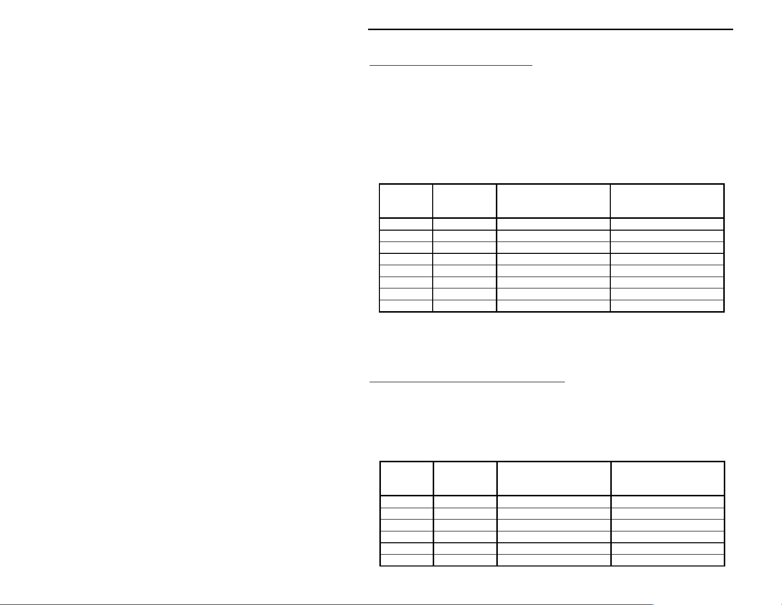
Receive Audio Connections
Table 1 below shows where you would place a jumper if
your radio has RECEIVE AUDIO on one of the microphone
pins. For example, if your radio has RECEIVE AUDIO on
pin 3 on a Kenwood microphone, you would place a jumper
on position R3A in the RECEIVE section of header HD1.
If your radio does not have RECEIVE AUDIO on one of the
microphone pins, then do not place a jumper in the
RECEIVE section of header HD1.
Radio
MIC Pin
*
1 HD1 RECEIVE--R1A RECEIVE--R8A
2 HD1 RECEIVE--R2A RECEIVE--R7A
3 HD1 RECEIVE--R3A RECEIVE--R6A
4 HD1 RECEIVE--R4A RECEIVE--R5A
5 HD1 RECEIVE--R5A RECEIVE--R4A
6 HD1 RECEIVE--R6A RECEIVE--R3A
7 HD1 RECEIVE--R7A RECEIVE--R2A
8 HD1 RECEIVE--R8A RECEIVE--R1A
MFJ-1272M
Header
Jumper Placement
for
Kenwood & Yaesu
Jumper Placement
for
Icom & Radio Shack
Table 1
*Refer to
External Audio
, page 3
PTT (Push-to-Talk Connections)
Table 2 below shows where you would place a jumper,
depending on what microphone pin is designated, PTT.
For example, if PTT is designated as being pin 4 on a
Kenwood microphone, then you would place a jumper on
position, R4B in the PTT section of header HD1.
Radio
MIC Pin
1 HD1 PTT--R1B PTT--R8B
2 HD1 PTT--R2B PTT--R7B
3 HD1 PTT--R3B PTT--R6B
4 HD1 PTT--R4B PTT--R5B
5 HD1 PTT--R5B PTT--R4B
6 HD1 PTT--R6B PTT--R3B
MFJ-1272M
Header
Jumper Placement
for Kenwood & Yaesu
Jumper Placement
for Icom & Radio
Shack
7
Page 8

MFJ-1272M Instruction Manual
7 HD1 PTT--R7B PTT--R2B
8 HD1 PTT--R8B PTT--R1B
Table 2
8
Page 9

MFJ-1272M Instruction Manual
Audio Out Connections
Table 3 below shows where you would place a jumper,
depending on what microphone pin is designated MIC.
The microphone designated MIC, is the pin that the
transmit audio from the TNC comes into the radio. For
example, if MIC is designated as being pin 1 on a
Kenwood microphone, then you would place a jumper on
position R1C in the AUDIO OUT section of header HD1.
Radio
MIC Pin
1 HD1 AUDIO OUT--R1C AUDIO OUT--R8C
2 HD1 AUDIO OUT--R2C AUDIO OUT--R7C
3 HD1 AUDIO OUT--R3C AUDIO OUT--R6C
4 HD1 AUDIO OUT--R4C AUDIO OUT--R5C
5 HD1 AUDIO OUT--R5C AUDIO OUT--R4C
6 HD1 AUDIO OUT--R6C AUDIO OUT--R3C
7 HD1 AUDIO OUT--R7C AUDIO OUT--R2C
8 HD1 AUDIO OUT--R8C AUDIO OUT--R1C
MFJ-1272M
Header
Jumper Placement
for Kenwood & Yaesu
Jumper Placement
for Icom & Radio
Shack
Table 3
Ground Connections
Table 4 below shows where you would place a jumper
depending on what microphone pin is designated GROUND.
For example, if GROUND is designated as being pin 7 on
a Kenwood microphone, then you would place a jumper on
position R7D in the GROUND section of header HD2.
Radio
MIC Pin
1 HD2 GROUND--R1D GROUND--R8D
2 HD2 GROUND--R2D GROUND--R7D
3 HD2 GROUND--R3D GROUND--R6D
4 HD2 GROUND--R4D GROUND--R5D
5 HD2 GROUND--R5D GROUND--R4D
6 HD2 GROUND--R6D GROUND--R3D
7 HD2 GROUND--R7D GROUND--R2D
8 HD2 GROUND--R8D GROUND--R1D
MFJ-1272M
Header
Jumper Placement
for Kenwood & Yaesu
Jumper Placement
for Icom & Radio
Shack
9
Page 10

MFJ-1272M Instruction Manual
Tabel 4
Always use the MIC pin designated as GROUND (not mic
ground). The use of MIC GROUND could result in audio
"hum" in the system.
10
Page 11

MFJ-1272M Instruction Manual
Through Connections
Table 5 below shows where you would place jumpers,
depending on the microphone pin functions that are not
to be switched by the MFJ-1272M. Microphone pins
designated, +V, UP, DWN, are radio functions that are
not needed by the TNC, but are needed for normal
microphone operations. For example, if on a Kenwood
microphone pin 3 is designated as being UP, which would
be for increasing your frequency readout on the radio,
then you would place a jumper on the HD2 header
position on the MFJ-1272M PC board labeled R3E-M3A.
Radio
MIC Pin
1 HD2 R1E - M1A R8E - M8A
2 HD2 R2E - M2A R7E - M7A
3 HD2 R3E - M3A R6E - M6A
4 HD2 R4E - M4A R5E - M5A
5 HD2 R5E - M5A R4E - M4A
6 HD2 R6E - M6A R3E - M3A
7 HD2 R7E - M7A R2E - M2A
8 HD2 R8E - M8A R1E - M1A
MFJ-1272M
Header
Jumper Placement
for Kenwood & Yaesu
Jumper Placement
for Icom & Radio
Shack
Table 5
Mic Audio Connections
Table 6 below shows where you would place a jumper,
depending on what microphone pin is designated, MIC
AUDIO. For example, if on a Kenwood, MIC AUDIO is
designated as being pin 5 of the microphone, then you
would place a jumper on position M5B in the AUDIO IN
section of header HD2.
Radio
MIC Pin
1 HD2 AUDIO IN--M1B AUDIO IN--M8B
2 HD2 AUDIO IN--M2B AUDIO IN--M7B
3 HD2 AUDIO IN--M3B AUDIO IN--M6B
4 HD2 AUDIO IN--M4B AUDIO IN--M5B
5 HD2 AUDIO IN--M5B AUDIO IN--M4B
MFJ-1272M
Header
Jumper Placement
for Kenwood & Yaesu
Jumper Placement
for Icom & Radio
Shack
11
Page 12

MFJ-1272M Instruction Manual
6 HD2 AUDIO IN--M6B AUDIO IN--M3B
7 HD2 AUDIO IN--M7B AUDIO IN--M2B
8 HD2 AUDIO IN--M8B AUDIO IN--M1B
*Refer to
External Audio
Table 6
, page 3
12
Page 13

MFJ-1272M Instruction Manual
The jumper listings on the previous tables do not
always hold true for all Kenwood, Yaesu, Icom and Radio
Shack transceivers. The best way to setup the MFJ-
1272M correctly, is to have your transceiver manual
handy at the time of setup. Having your transceiver
manual handy will ensure that you setup the MFJ-1272M
properly, by making the right connections the first
time.
If you find yourself in need of technical help, please
refer to the
Technical Assistance
section of this
manual. Please have all necessary notes and data
ready, so we can provide you with the best possible
service at the time of your call.
: Jumper positions for specific radios are detailed
Note
on page 8.
: The FT-2400H and FT-2500H are the only Yaesu VHF
Note
transceivers that are compatible with the MFJ1272M. All others, such as the FT-3000, FT-8000,
and FT-8500, use data ports for packet data.
13
Page 14

MFJ-1272M Instruction Manual
Jumper Placement Diagrams for specific radios
14
Page 15

MFJ-1272M Instruction Manual
Other Notes
All of the jumper designations and wiring on the MFJ1272M come setup for Yaesu and Kenwood transceivers.
So, if your RECEIVE AUDIO is on pin 3 of your Kenwood
microphone, then you would place a jumper on R3A in the
RECEIVE section of HD1. You may need to change the
installed jumpers for the radio you are trying to use.
The MFJ-1272M is compatible with the the Yaesu FT-2400H
and FT-2500H. All other Yaesu transceivers will either
be the standard round 8-pin screw-on type, or in the
case of the FT-3000, FT-8000 and FT-8500, all packet
data is taken in and out through the DATA PORT in the
back of the radio. In this case, the MFJ-1272M is
totally incompatible.
If you want to use the MFJ-1272M with an Icom or Radio
Shack transceiver, then all jumper designations need to
be thought of in reverse order. This is due to the
numbering scheme on the Radio Shack and Icom
microphones. So if your RECEIVE AUDIO is on pin 3 of
your Icom microphone, then you would place a jumper on
R6A in the RECEIVE section of HD1.
The MIC pins on the Radio Shack and Icom radios are
numbered 1 through 8, from left to right. Whereas, the
Yaesu and Kenwood radio MIC pins are numbered 1 through
8, from right to left. The only Yaesu transceivers
that are compatible with this unit are the FT-2400 and
FT-2500. All other Yaesu transceivers, such as the FT3000, FT-8000, and FT-8500, use data ports, which are
located in the back of the radios for all packet type
communications.
15
Page 16

MFJ-1272M Instruction Manual
16
Page 17

MFJ-1272M Instruction Manual
This means that the labels on the MFJ-1272M printed
circuit board are backwards for the Icom radios, such
as the IC-2340, IC-2350, IC-281H, IC-2000H, and IC-706.
This also holds true for the Radio Shack HTX-212 VHF
transceiver.
For example, MIC audio is designated as pin 6 in the
ICOM IC-2340 manual, but on our MFJ-1272M board it is
pin 3, so R3C and M3B have jumper clips on them. All
other pin designations for the Icom and Radio Shack
radios are also backwards.
Connections
Connection of the MFJ-1272M is very simple.
1.
Connect your radio's microphone to the microphone
connector on the front panel of the MFJ-1272M. Make
sure that that you hear a ‘‘click’’ when the
microphone snaps into place.
2.
Connect the gray, 8-pin MIC plug, which exits the
rear of the MFJ-1272M out of the TO RADIO slot, to
the microphone jack on the radio.
3.
Connect the TNC cable, which exits the rear of the
MFJ-1272M out of the TO TNC slot, to the TNC.
External Receive Audio Connection
If you have a radio without RECEIVE AUDIO on the
microphone connector, you will need to perform steps 4
and 5.
4.
Connect a cable from the headphones or speaker out
jack of the radio to the AUDIO IN jack of MFJ-1272M.
The AUDIO IN jack on the TNC/MIC switch requires an
RCA male phono plug.
5.
Connect a speaker to the EXT. SPKR jack on the back
of the MFJ-1272M. The EXT. SPKR jack requires a
17
Page 18

MFJ-1272M Instruction Manual
3.5mm mono plug, with the tip being positive and the
sleeve ground.
18
Page 19

MFJ-1272M Instruction Manual
Technical Assistance
If you have any problem with this unit first check the
appropriate section of this manual. If the manual does
not reference your problem or your problem is not
solved by reading the manual, you may call MFJ
Technical Service at
601-323-5869
. You will be best helped if you have your
unit, manual and all information on your station handy
so you can answer any questions the technicians may
ask.
You can also send questions by mail to MFJ Enterprises,
Inc., 300 Industrial Park Road, Starkville, MS 39759;
by Facsimile to 601-323-6551; or by email to
techinfo@mfjenterprises.com. Send a complete
description of your problem, an explanation of exactly
how you are using your unit, and a complete description
of your station.
601-323-0549
or the MFJ Factory at
19
Page 20

MFJ-1272M Instruction Manual
Schematic
20
 Loading...