

MFJ MFJ-1272BYH, MFJ-1272B, MFJ-1272BX, MFJ-1272BYV, MFJ-1272BZ User Manual

MFJ-1272B TNC/Microphone Switch
Introduction
Thank you for purchasing the MFJ-1272B TNC/MIC Switch. This switch is
designed to allow simultaneous connection of both your microphone and
your TNC to the radio.
The MFJ-1272B microphone switches were designed to be used with any
radio that has a standard, round, 8-pin microphone connector. Because
many TNCs have different connectors, MFJ offers 5 models:
MFJ Model Number TNC and Multimodes
MFJ-1272B All MFJ TNCs, TAPR TNC II clones, and PK12/96/900
MFJ-1272BX PK-232
MFJ-1272BYV KAM® VHF port, KPC-2, KPC-3
MFJ-1272BYH KAM HF port
MFJ-1272BZ PK-88
For circuit board revisions, refer to page 11.
CAUTION
Always check your radio's owner's manual to see if there is a voltage on one
of the pins of the microphone before hooking up the microphone switch.
You could damage your radio by connecting the PTT line to a voltage source.
Do not connect any pin labeled as a voltage source to PTT !
WARNING: MFJ Enterprises, Inc. is not responsible for damaged radios or
associated equipment. It is your responsibility to make sure
your connections will not damage the radio.
KAM is a registered trademark of Kantronics Company, Inc.

MFJ-1272B
Instruction Manual
Installation
Before you install the MFJ-1272B TNC/MIC switch, you must set it up for
your particular radio. The MFJ-1272B comes pre-wired from the factory for
Kenwood and Alinco radios
If you have one of these radios, the TNC/MIC switch is ready to use. If you
have a Kenwood or Alinco radio
jack, or if your radio is not a Kenwood or Alinco refer to the configuration
section. We have given a few diagrams for placing the internal jumpers for a
few popular radios on Page 7.
without
RECEIVE AUDIO on the microphone jack.
with
RECEIVE AUDIO on the microphone
Configuration
If you must configure the TNC/MIC switch for your radio, please follow this
procedure.
1. Remove the two screws and top cover of the MFJ-1272B.
2. Look at the writing on the unit's pc board. Please refer to Tables 1 thru
6 as to where to place the jumpers in relation to the pinouts on your
radio.
signals.
Audio Out:
Audio to the from either the TNC or radio MICROPHONE.
Consult your radio's manual
and the definitions below to match
PTT:
This is the Push to talk signal from either the TNC or radio microphone.
Receive:
Audio from the radio to the TNC. Please refer to the External Audio
section on the following page, if you use external audio make no
connection here.
Audio In:
Audio from mic (same # as Audio Out)
Ground:
This is the system ground on radio's mic connector. Some radios have
two ground pins, MICROPHONE GROUND and GROUND. The
microphone ground
introducing "hum" into the system
Throughs:
Connect all pins here except MICROPHONE AUDIO.
2
should not
be used, due to the possibility of
.
Always use the pin labeled ground.

MFJ-1272B
Instruction Manual
(unlabled)
if you use external audio do not connect the radio pins for Receive
3. Header HD3 controls the RECEIVE AUDIO to the EXTERNAL SPEAKER.
Place a push-on jumper on pins 2 and 3 if you want the external
speaker "on" all of the time. Place the jumper on pins 1 and 2 if you
want the external speaker "off" when using the TNC. Most people
prefer not to hear audio during packet.
4. Replace the top and screws.
External Audio
If your radio does not have RECEIVE AUDIO on the microphone, then we
suggest the use of an inter-connecting to supply RECEIVE AUDIO to the
TNC/MIC switch. You would connect a cable from an external speaker or
headphones jack on your radio to the AUDIO IN jack of the TNC/MIC switch.
Therefore, no jumper connection should be made for Receive on the pc
board.
Using the method above for connecting RECEIVE AUDIO to the TNC/MIC
switch, will cut off the internal speaker inside the radio. In this case, you
must connect an external speaker to the EXT. SPEAKER jack on the TNC/MIC
any
switch. Otherwise, you will not be able to hear
radio.
signals at all from your
Jumper Configuration
Because there are so many different radio configurations, we have tried to
make the MFJ-1272B as versatile as possible. With the MFJ-1272B you can
virtually connect any radio pin to just about any TNC pin, just by configuring
the jumpers properly. The following tables will show how to set the jumpers,
depending on the TNC functions versus the MIC pins of a particular radio.
Be sure to follow the tables closely with your radio manual, to verify that you
are not shorting any microphone voltages or any other microphone signals to
GROUND !
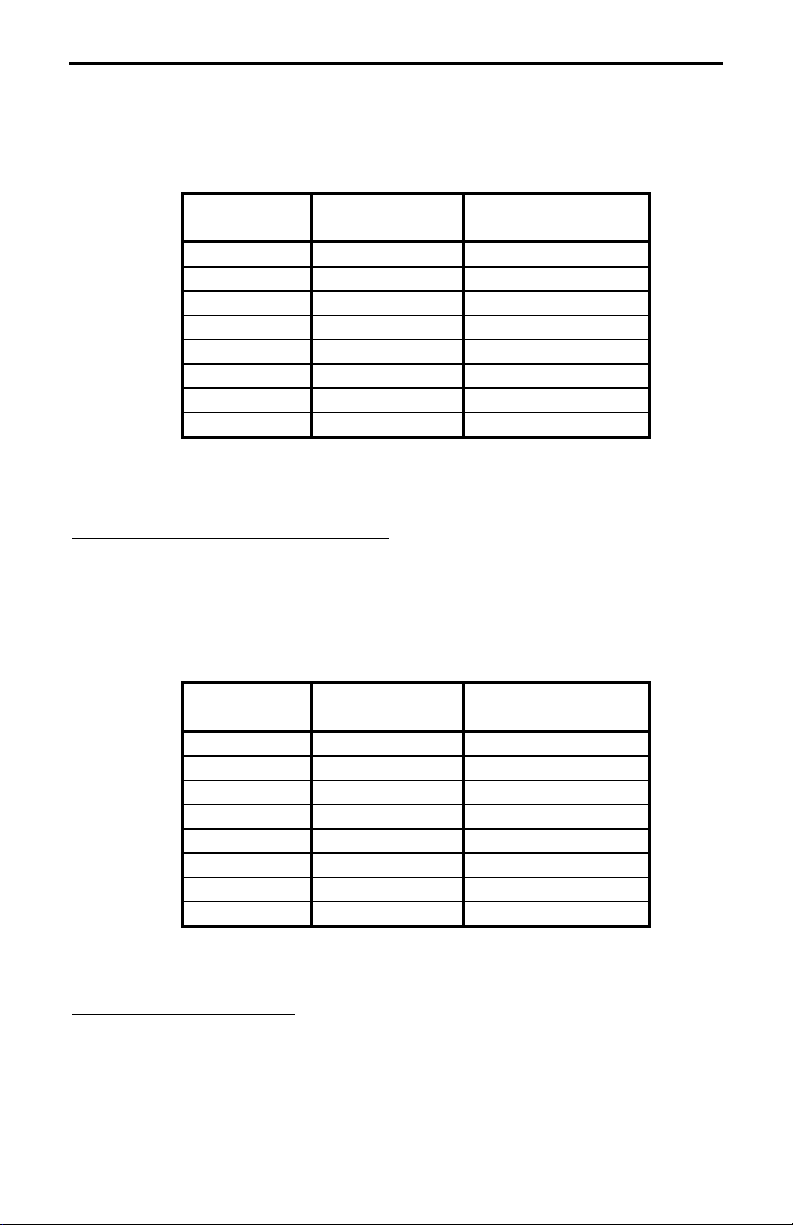
Receive Audio Connections
Table 1 shows where you would place a jumper if your radio had RECEIVE
AUDIO on one of the microphone pins. For example, if your radio had
RECEIVE AUDIO on pin 3 on a Kenwood microphone, you would place a
jumper on position, R3A in the RECEIVE section of header HD1. If your radio
3
MFJ-1272B
does not have RECEIVE AUDIO on one of the microphone pins, then
Instruction Manual
do not
place a jumper in the RECEIVE section of header HD1.
Radio MIC Pin MFJ-1272B
Header
1 HD1 RECEIVE--R1A
2 HD1 RECEIVE--R2A
3 HD1 RECIEVE--R3A
4 HD1 RECEIVE--R4A
5 HD1 RECEIVE--R5A
6 HD1 RECEIVE--R6A
7 HD1 RECEIVE--R7A
8 HD1 RECEIVE--R8A
Place a jumper on:
Table 1
*Refer to External Audio, page 3
PTT (Push-to-Talk) Connections
Table 2 shows where you would place a jumper, depending on what
microphone pin is designated PTT. For example, if PTT is designated as
being pin 4 on a Kenwood microphone, then you would place a jumper on
position R4B in the PTT section of header HD1.
Radio MIC Pin MFJ-1272B
Header
1 HD1 PTT--R1B
2 HD1 PTT--R2B
3 HD1 PTT--R3B
4 HD1 PTT--R4B
5 HD1 PTT--R5B
6 HD1 PTT--R6B
7 HD1 PTT--R7B
8 HD1 PTT--R8B
Place a jumper on:
Table 2
Audio Out Connection
Table 3 shows where you would place a jumper, depending on what
microphone pin is designated MICROPHONE AUDIO. The microphone pin,
designated MICROPHONE AUDIO, is the where the transmit audio from the
4
 Loading...