

Page 1
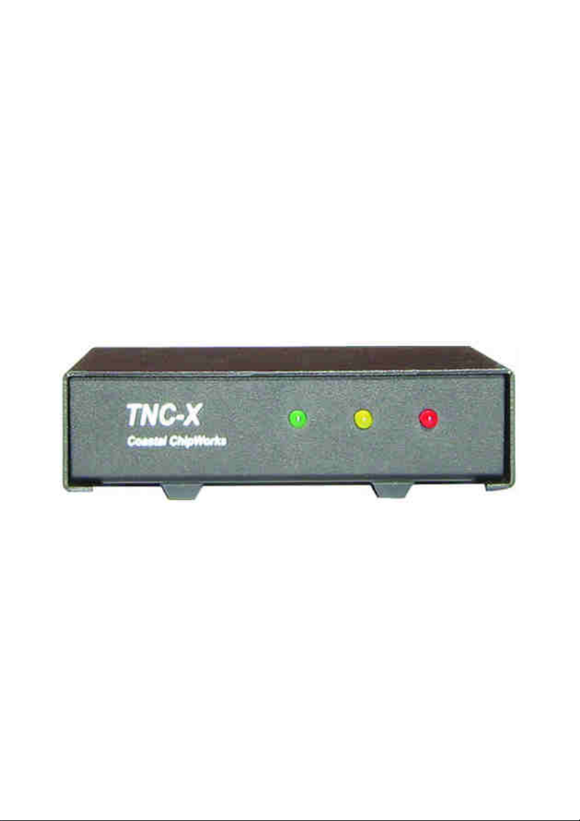
TNC-X Packet Controller
Model MFJ-1270X
INSTRUCTION MANUAL
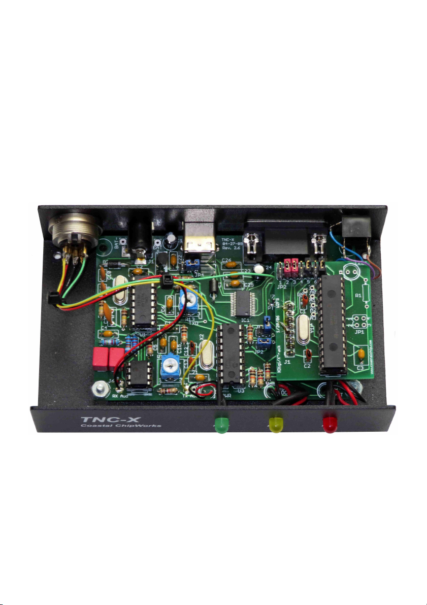
Digipeater Daughter Board below ...
Page 2

Introduction
Thank you for purchasing the MFJ-1270X TNC-X Packet Controller. The MFJ-1270X
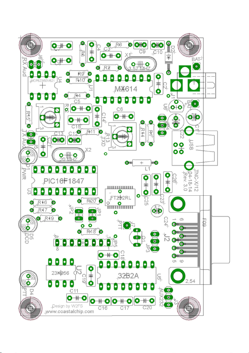
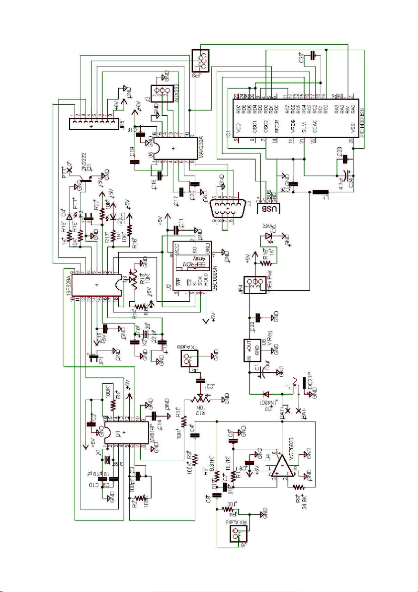
is a new Terminal Node Controller design based on the Chepponis/Karn KISS protocol. It is implemented using a Microchip PIC 16F628A microcontroller, a CML
MX614 Bell 202 modem chip, an 8k Ramtron FRAM, a MAX232A level converter
chip, and an op-amp which provides active audio filtering for the modem. From
the beginning, this TNC was designed to be small, inexpensive, have low power
consumption, and expandable.
The MFJ-1270X features an on-board USB port. The USB port was added because
the design took into consideration that computers these days lack the old style
RS-232 serial ports. There is also an 8-pin expansion header that allows the addition of "daughter boards". Power is provided to the daughter board through the
expansion header. In addition, signals that would otherwise go to or from a host
PC can be intercepted by the daughter board at the TTL level and processed. The
I/O on the expansion header speaks "KISS" so that any daughter board only has
to send and receive data packaged in KISS format to access the core module.
This makes the development of daughter boards fairly simple and inexpensive.
For example, daughter boards are now available that can turn the MFJ-1270X into
either of two types of digipeaters, or into a stand alone APRS Tracker.
In addition, the expansion header provides access to a second on-board serial
port. The X-Track daughter board, for example, uses this port to receive data
from a GPS receiver. The data is then processed and formed into packets and an
APRS beacon is sent. Even without daughter boards the MFJ-1270X works as a
fully functional stand alone KISS mode TNC.
The idea behind the expansion options was to provide a platform that would allow additional functionality to be added to the unit with the investment of very little design time and very few parts.
Power Requirements
IMPORTANT: DO NOT PLUG IN THE 8-15 VDC POWER SUPPLY AND THE 9-VOLT
BATTERY AT THE SAME TIME!
The power requirements of the MFJ-1270X are very minimal due to the low power consumption of the design. Using an 8-15 volt DC power supply capable of
200-300 mA is well within the consumption specifications. There is also a 9-volt
Page 3

battery snap provided for a 9-volt battery. This makes the TNC more portable for
campers and backpackers.
Terminal Speed
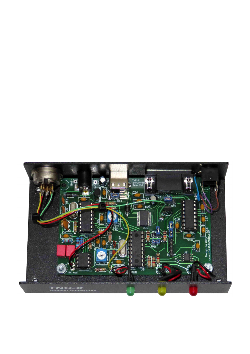
The MFJ-1270X supports only 4 terminal speeds. Jumpers JP1 and JP2 determine
the speed strictly for the link between the TNC and the computer. The following
settings are allowed:
JP1 JP2 Port Speed
On On 1200 baud (default)
On Off 4800 baud
Off On 9600 baud
Off Off 19200 baud
Note that the terminal speed setting does not affect the speed to transmit data.
The out-going or transmit speed is always 1200 baud. Note also that if you set
this baud rate faster than 1200 baud, it is possible for data to be fed into the modem faster than it can transmit it over the air. This may eventually result in the
transmit buffer filling up.
Setup If You Are Using USB
If you have elected to use the USB port to provide data communications to your
PC, you should begin by acquiring and installing the drivers for the PC and operating system that you are using. The driver you need is a Virtual Com Port (VCP)
driver. It will make the TNC appear as an additional com port on your computer
so that you can use any packet radio software that supports a KISS TNC connected to a standard serial port.
If you use the USB port, do not supply any power to the TNC through the power
jack.. The USB buss can supply the rather limited power requirements for the
TNC. If you are using the
5 USB option, set the board jumpers as follows:
JP3 On the left two pins (toward C24)
JP4 Connect the center pin to the pin that is closest to the center of the
board.
JP5 Jumper pins 1 and 2 (the end closest to Q1) and pins 3 and 4, unless
you are using a daughter board.
MFJ-1270X Instruction Manual TNC-X Packet Contoller
Page 4
Setup If You Are Using the TNCs Serial Port
If you plan to connect the TNC to a standard computer serial port, set up the
jumpers as follows:
JP3 On the right two pins (toward U5)
JP4 Connect the center pin to the pin closest to C22.
JP5 Jumper pins 1 and 2 (the end closest to Q1) and pins 3 and 4.
If you are using the on-board serial port, you must supply power to the TNC. This
can be done in one of two ways. There is a coaxial power jack on the board that
can be used to receive anything from 8 to 15 volts DC. Alternatively you can connect a 9-volt battery to the location marked BAT.
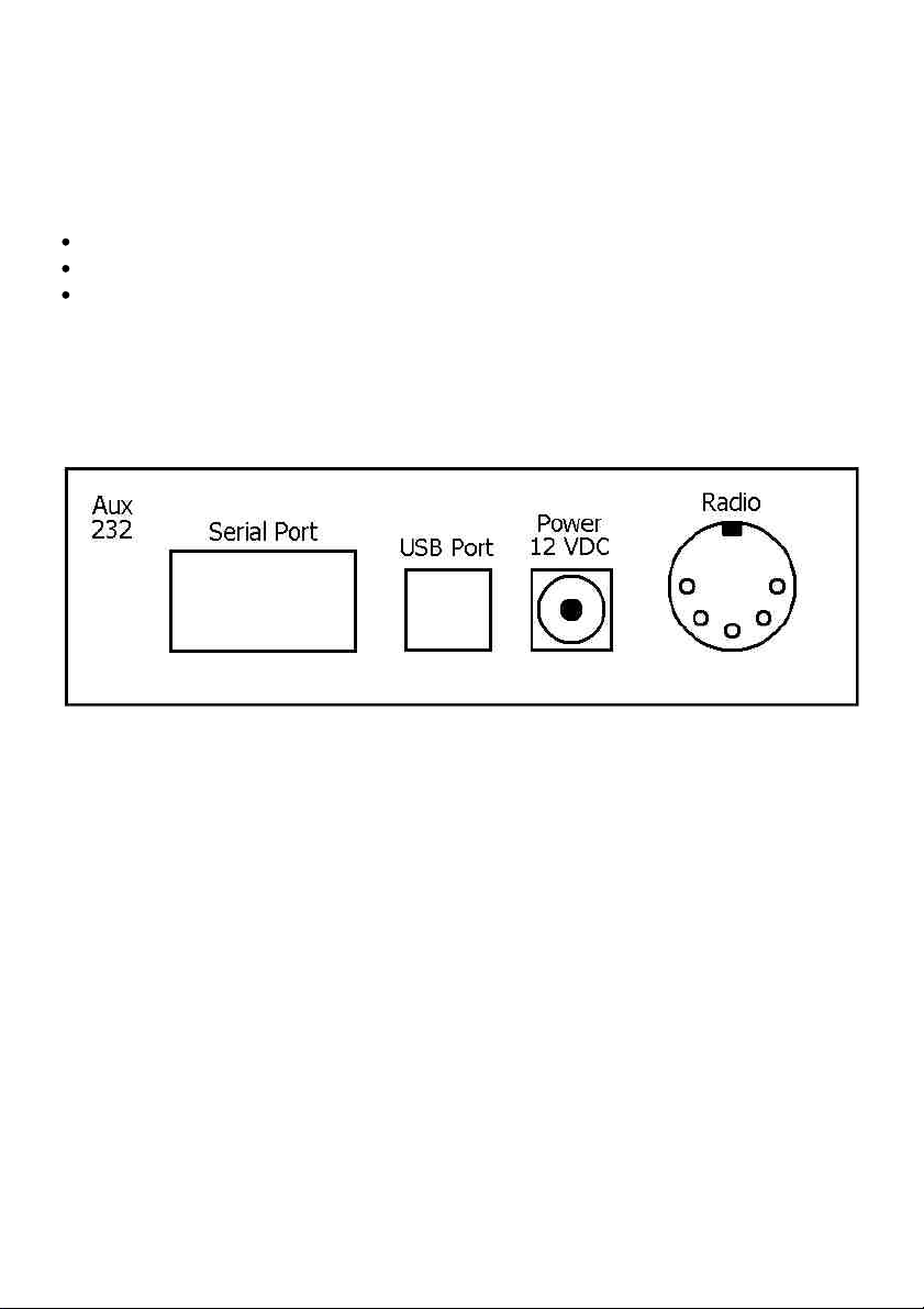
Aux 232
An auxiliary serial port using a MAX232 level converter. Main purpose is for GPS
input for the X-Track daughter board.
Serial Port
A standard DB 9-pin RS-232C serial port.
USB Port
A standard USB port for computers that lack the old style RS-232 serial ports.
Power 12VDC
A coaxial power jack for main power input. Center pin is positive and sleeve is
negative.
RADIO
A 5-pin DIN connector used to interface the radio to the TNC.
Page 5
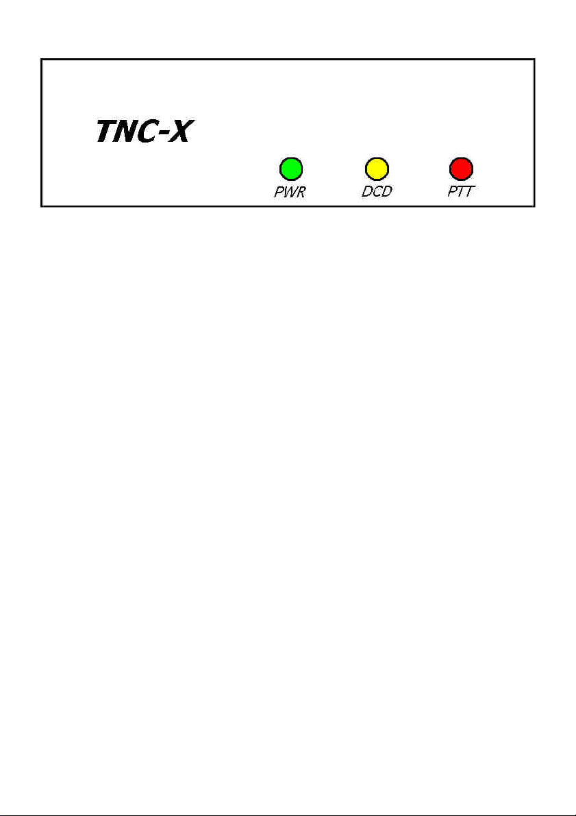
POWER
Indicates the MFJ-1270X has power supply voltage supplied.
RECEIVE DCD
Indicates the MFJ-1270X is receiving a data packet signal from the radio.
TRANSMIT PTT
Indicates that the MFJ-1270X is transmitting data signal from the radio.
Page 6

Radio Setup
The radio connections are made via a 5-pin DIN chassis mounted connector. The
connector is shown below:
Back View of Connector
Radio Port Connections
These are the radio port pins and their respective functions. Match the proper pin
and its function to the same pin and function on your radio.
Pin 1 – Microphone Audio: Supplies audio from the TNC to your radio.
Pin 2 – Ground: Common connection for audio and PTT common.
Pin 3 – Push-to-Talk: Allows the TNC to key your transmitter to transmit.
Pin 4 – Receive Audio: Supplies audio from the radio to the TNC.
Pin 5 – No Connection
Troubleshooting
The MFJ-1270X is designed to give years of service. However, as with all things
sometimes problems do come up and need to be taken care of. Here are a few
troubleshooting tips in the event that something does go wrong.
Page 7

Voltage Supply
If the supply voltage is suspect this must be corrected first. The first thing to do
is to check the main voltage supply to the TNC. Do this using a DC voltmeter capable of measuring +5 volts DC. The main supply voltage to the TNC must be at
least 7 to 8 volts DC. The TNC uses a 78L05 voltage regulator. The voltage regulator needs to see a voltage at least 2 volts greater than the regulation voltage. If
the main supply voltage is not 2 volts greater than +5 volts, then the regulator
will not work, thus not having a +5 volt DC output. To check this, do the following:
1. Set your voltmeter to read +5 volts DC.
2. Remove the main supply from the TNC. Check the voltage at the connector
that plugs into the TNC. The voltmeter should indicate +5 ±0.5 volts DC. If
the reading is lower, then check the main power source. If the reading is
good, then move on to step #3.
3. With the main power still removed from the TNC, carefully remove all IC
chips from the TNC.
4. Reconnect the main power source into the TNC and re-check the +5 volts
DC.
5. If you are using the computers USB port to supply voltage to the TNC, measure the voltage between ground and the right pin on JP4 or the right pin if
you use power jack. It should be approximately +5 volts DC. If not, then we
strongly recommend returning the TNC for service. If the voltage is good,
then move on to the next section.
Testing for Defective IC Chips
If you are reading this section, it means that you have determined that your TNC
has a defective IC chip. The procedure for checking for a defective IC is not complicated, but you should follow the procedure carefully. If you do not follow the
procedure carefully you can and probably will damage an otherwise good IC
and/or the TNC…so please be very careful.
1. Remove power from the TNC, either by removing the main supply at the
power jack or the USB port cable.
Page 8

2. Carefully remove all IC chips from the TNC. Make note as to the orientation
of each IC in their respective IC sockets and which sockets the ICs came out
of. Be careful not to bend any of the pins of the ICs. IMPORTANT!
3. Carefully re-insert one IC at a time into its respective socket and recheck the
+5 volts DC. If any IC causes the +5 volts DC to drop, then the IC that causes the voltage drop is your defective part. Be sure to check all IC chips, because you could have more than one defective part. Call the MFJ Service
Dept. for a replacement part.
Testing Receive
Hook up a receiver audio source to the receive pins on the board (or the mono
jack if you are using the enclosure). Make sure audio goes to the positive pin.
Make sure the squelch is left open. When a data packet is received, you should
see the yellow LED light briefly and go out. Even when no data is being received
it is normal for the yellow LED to flicker. However, it should come solidly on when
a packet is received. Assuming that this checks out, run a serial program of some
kind on your PC, set the baud rate to whatever baud rate you specified with JP1
and JP2. Confirm that you are receiving data (note, this will be raw KISS frames
so much of it may look like garbage, but you should see some recognizable data).
Note that if you are using the USB option, you must the USB drivers loaded on
your computer.
If you do not see the yellow light come on, first confirm that audio is getting to
the TNC (a scope or a small headphone may be useful for this). If it is, verify that
audio is coming out of Pin 6 of U4. Assuming this is working, if you have a scope
or frequency counter, measure the frequency on Pin 1 of U1. It should read about
3.57 MHz. While you are at it, check Pin 16 of U3. It should read about 20 MHz.
If at any point you don’t get the measurement you expect, carefully check the
solder joints in that part of the board. If the yellow light comes on but you see no
data on your PC, start at Pin 8 of U3 and trace the data signal to header Pin 1, to
header Pin 2 and on to Pin 10 of U5. It should come out at Pin 7 of U5.
Next check out the transmit chain. The TXDelay is set by R13. Start by setting it
at about halfway (which will correspond to a TXDelay of about 240 ms (or a setting of 25 on most TNC’s). At this point you need to be running a program on
your PC that supports KISS mode. The TNC-X webpage (www.tnc-x.com/documentation.htm) has a program called TXTest, which is a very simple program that
can be used to test your transmit chain.
Page 9
When you transmit a packet, you should see the red LED come on briefly. Hook
the transmit audio and PTT up to a radio and try transmitting. R12 is used to adjust the transmit level. If you don’t have a means of measuring the deviation precisely, monitor your signal on a receiver and slowly increase R12 until you hear no
further increase in volume on the receiver. Then back it off a bit. Even if the TNC
is not connected to a radio, you should see the red light come on when you
transmit data via the TNC.
Many people use TNC-X for APRS applications. There are many good software
programs available for this application (WinAPRS, UI-View for Windows, for example). For a general purpose TNC program that supports KISS, you might want to
take a look at WinTNC. It has recently been revised so that it works under Windows XP, as well as older versions of Windows. If you want to use AGWPE, there
is a link on the TNC-X webpage that contains detailed instructions.
If you have any problems with any of this, please contact MFJ Technical Services
at the phone number in the warranty instructions.
Page 10
Page 11
Page 12

Parts List:
Capacitors:
C1 10 µF electrolytic
C3 100 pF ceramic (marked 101J)
C2, C4, C5, C6, C11,
C14, C15, C16, C17,
C18, C19, C20, C26 µ01 Multilayer (marked 103)
C21, C22, C23, C25 µ1 monocap (small yellow - may be marked 104z)
C7, C8 µ01 Polyproplene (red/yellow block)
C9, C10 18 pF ceramic (marked 18J)
C12, C13 22 pF (ceramic (marked 22J)
C24 4µ7 electrolytic
Resistors: (note: there are no R5, R6 or R7)
R1, R2, R3 100 k (brown, black, yellow)
R8 24k9 1% (red, yellow, white, red, brown)
R9 9k31 1% (white, orange, brown, brown, brown)
R10 18k7 1% (brown, grey, purple, red brown)
R11, R14, R16, R18,
R20 10 k (brown, black, orange)
R4, R15, R17, R19 1k (brown, black, red)
R12, R13 10k potentiometer
Diodes (note: there is no D3)
D1 green LED
D2 1N4001
D4 red LED
D5 yellow LED
Headers, Jumpers
JP1, JP2 2 Pin Header
JP3, JP4 3 Pin Header
JP5 8 Pin Header
6 Shorting blocks for the above headers.
Page 13

Other Components
X1 3.57 MHz Crystal (may be labeled A035)
X2 20 MHz Crystal (may be labeled A200)
Q1 2N2222 or similar
IC1 FT232RL USB interface chip
U1 CML614 Modem Chip - 16 pins
U2 FM25640 FRAM memory chip
U3 PIC16F628A or PIC16F648A
U4 MPC6023 OpAmp
U5 SP232A or HIN232A
U6 78L05 Voltage Regulator
F09 DB9 Female PC mount Connector
J1 Coaxial Power Connector (Center Pin is Positive=
USB USB connector
L1 Ferrite Board (looks like a 1N4001 diode, but no stripe)
Radio Port 5-pin DIN Chassis Mount Connector
AUX 232 2.5 mm Stereo Chassis Mount Connector
Page 14
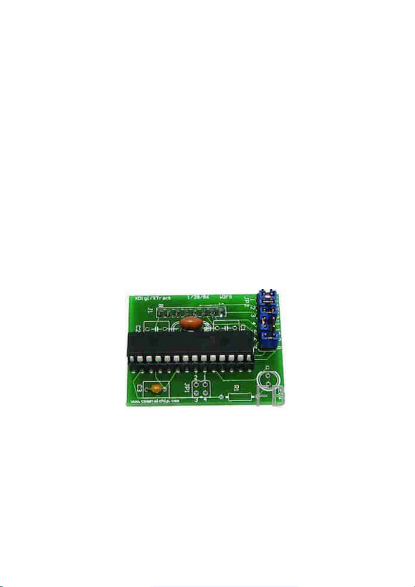
X-DIGI
TNC-X Digipeater
Daughter Board
Model MFJ-1270DG
Page 15

Introdution
X-Digi is a daughter board for the TNC-X KISS mode TNC. It is designed to emulate the most popular features of the widely used UI-DIGI EEPROM for TNC-2s. In
addition, X-Digi provides digipeater services for both UI APRS frames and for connected packets. It makes it easy to put up a temporary digipeater to fill in coverage "holes" in emergency situations. It consumes very little current. Both TNC-X
and X-Digi can be powered all day on a single 9 volt battery. It can be configured
in the field through the TNC-X serial port using any computer with any terminal
program. It also contains a "firmware bootloader" so that future firmware revisions can be easily uploaded using any Windows PC.
Installation Instructions
To install the X-Digi Daughter Board, first remove the two jumpers on header JP5
on the TNC-X (this is the 8 pin header). Then insert the X-Digi board so that the
notch on the 18F2525 is toward the back of the TNC-X. C3 will be toward the LED
side of the TNC-X board. Set the TNC-X so that it runs at 9600 baud: JP1 on the
TNC-X board should be off, while JP2 should be on.
Configuration Instructions
The X-Digi Daughter Board is configured via the standard TNC-X serial port. Connect your computer to the primary serial port. You can use either the serial port
connection or the USB port (if you have this option installed). You can even use a
hand held device like a Palm Pilot running a terminal program to configure the
device. However, you cannot connect the USB port on a Palm Pilot to the USB
port on TNC-X. To configure the X-Digi, set the 14 pin jumper block up as follows:
Corner of board =>
Run a terminal program on the PC that you have connected to the TNC-X serial or
USB port. If you are running a Windows computer, Hyperterminal will do fine, if
you are using the USB port to configure TNC-X, you may find the easiest way to
do this is to do this is to remove JP4 of TNC-X so that the USB module is powered
up but the TNC is not. Then run your terminal program (it will recognize the USB
serial port). Then replace JP4 to power up the TNC. Set your terminal program
Page 16

for 9600 baud and no flow control. Turn on the TNC-X with the X-Digi daughterboard installed and within 20 seconds strike any key in the terminal program to
get the X-Digi's attention. You should see the following menu:
X-Digi Ver 2.0E Configuration Menu
C. Set Digipeater callsign. :URCALL
A. Set Digipeater Alias. :URDIGI
F. Set UIFlood callsign. :NY
L. Set UIFlood Limit. :7
T. Set UITrace Callsign. :WIDE
M. Set UITrace Limit. :4
1. Set UICall 1. :
2. Set UICall 2. :
3. Set UICall 3. :
4. Set UICall 4. :
5. Set UICall 5. :
6. Set UICall 6. :
7. Set UICall 7. :
8. Set UICall 8. :
D. Set Dupe Time (x5 secs). :6
P. Set Remote Password. :
B. Set Beacons.
Q. Quit.
Enter Selection:
Choose the item you wish to reconfigure by pressing the letter or number in the
left hand column. The Callsign and Alias are fairly straightforward, but some of
the other parameters may require explanation. The UIFlood callsign supports the
WIDEn-N paradigm. When the digi receives a packet with a path of, say WIDE33, it will decrement the SSID value (to WIDE3-2) and retransmit the packet.
When it reaches WIDE3-0, it will replace this value with the X-Digis callsign. UITrace works in a similar manner, but adds X-Digis callsign to the path. So, for example, WIDE3-3 becomes URCALL, WIDE3-2 in the above example. The limits for
UIFlood and UITrace are provided to allow the X-Digi to stop overly long paths. In
the above case the UITrace limit is set to 3, so an incoming path of WIDE4-4, for
example, would be simply be digipeated as URCALL. The UICall fields allow you
to specify up to 8 calls for which X-Digi will simply do callsign substitution.
Page 17

For example, if you wanted to support RELAY (not currently recommended) you
could do so by adding this value in UICALL. Packets with a path of RELAY would
be digipeated with a path of URCALL. The menu also allows you to specify a dupe
time value in 5 second intervals. Duplicates are calculated based on a CRC that is
applied to the entire packet except for the path. So if X-Digi sees a packet with
the same source and destination address and the same contents within the time
period specified by dupetime, it will not digipeat it. Because this timer is set in increments of 5 seconds, a value of 6, for example, will result in a 30 second duplicate checking period. Do not set this value higher than about 24 (2 minutes). Setting the dupe value to 0 turns off dupe checking.
Selecting the B value from the menu brings up another menu that allows you to
set up the beacons. X-Digi supports 4 different beacons, each of which can be
sent at a different interval, have a different path, and have a different text. To set
up these beacons, hit the B key. The time values here are in increments of 5 seconds, so to set a beacon to transmit every 10 minutes, for example, you would
use a value of 120. The offset value allows you to specify a time period to elapse
before the first beacon is sent. For example, if you set Beacon 1 to be sent every
five minutes and Beacon 2 to be sent every 10 minutes, every other time you
would have both beacons sent at the same time. While this will work, you might
prefer to have X-Digi wait a minute or two before sending the first beacon so that
the two beacons would never be sent at the-same time. You can do this with offset.
The path for each beacon can also be set via this menu. Simply enter the path
with a comma between each callsign, for example W2SB,WIDE3-3. Selecting Q
will exit the beacon menu. Another Q will exit configuration.
After programming, turn off the unit and change the jumpers so that they are set
up as follows:
Corner of board =>
Also, make sure JP3 is toward U5. By using this setup, incoming data will be routed through to the PC serial port (but not the USB port). As a result, you will be
able to run a standard APRS program (such as WinAPRS, MacAPRS, UIView, etc.)
and watch the activity coming in to the digipeater. It is not necessary to operate
XDigi with a PC attached, it will work perfectly well as a stand alone unit. However, this option is available to you if you like. If you decide to run the XDigi as a
Page 18

stand alone unit, you can simply leave the jumpers in their "configuration" setting.
X-Digi is designed to be field upgradeable. It has boot loader built in that allows
you to upload new firmware if and when it becomes available. instructions on
how to use the boot loader are available on a link from the TNC-X webpage
http://www.tnc-x.com/firmware.htm.
There is a Yahoo group called XDigi that is available to support users of the X-Digi
daughter board. Announcements of firmware revisions will be posted to this
group.
Using the Remote SysOp Feature
As of version 2.0 of the X-Digi firmware, it is possible to change the parameters
of X-Digi remotely. Doing so requires a 5 letter password. All X-Digi parameters
except the password are remotely configurable. In order to use the remote sysop
feature, you must first set a remote password using the configuration procedure
described above. The password must have exactly 5 characters and is case sensitive. To disable the remote SysOp feature, set the password to five spaces.
When you boot up X-Digi, it will wait 20 seconds for a command to reconfigure
before it starts up. When the 20 second timer has expired, XDigi will send the
text in the first beacon to let you know it is in digipeater mode (and is available
to be remote sysop-ed.
To reconfigure X-Digi remotely, change the UNPROTO parameter in your remote
TNC to specify the callsign that is configured in X-Digi. So, for example, if the XDigi cailsigri is UR0CAL you could set up UNPROTO as follows:
UNPROTO UR0CAL
After you have changed the UNPROTO parameter, go into converse mode (with a
k on most TNCs) and hit the return key. This will send an empty packet out using
the UNPROTO path.
When X-Digi hears your transmission, it will respond with a string of four letters.
This four letter combination is a function of a random number generator inside XDigi and the password that you have specified. You must then respond with the
proper 4 letter code in order to enter remote sysop mode. This code can be obtained from a program that is available on the XDigi webpage (http://www.tnc-
Page 19
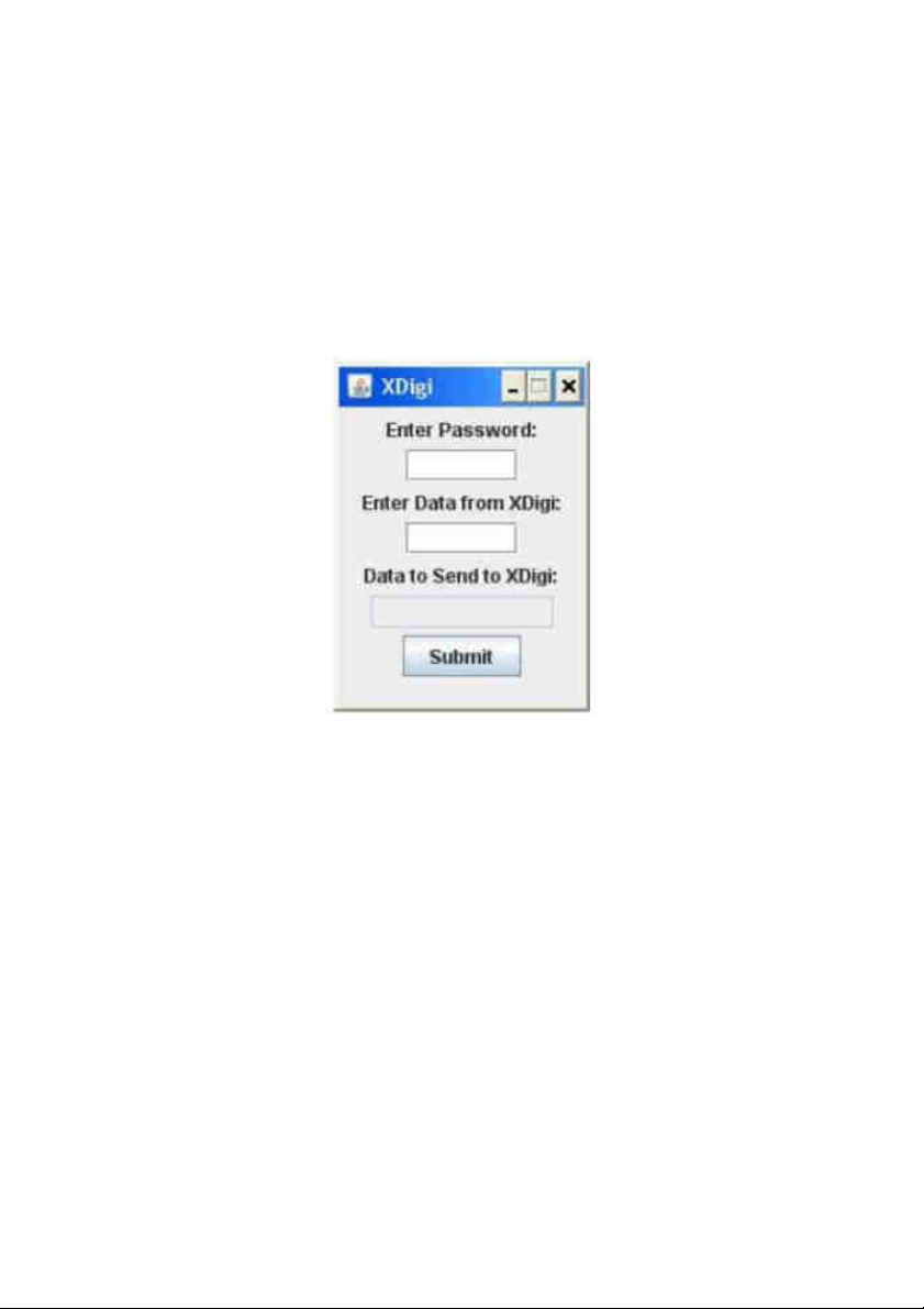
x.com/XDiqi.htm) called calcpw.jar. The program was written in Java, so it should
run on any platform and it is an executable .jar file so you should be able to run
it simply by double-clicking on it. Of course you will need to have the Java runtime environment on your computer to run the program, but most computers
these days already have this loaded. This program is fairly self-explanatory. You
enter your password (the one you entered in the configuration screen) and the
four letter code you received from X-Digi, and then it tells you what your response should be. Send the response back to the X-Digi. The X-Digi will respond
with either "yes" (if you were successful) or "not" if you were not.
Once you have successfully entered remote sysop mode, you can send commands to the X-DIGI in the form:
X value
for commands from the first configuration page.
Page 20

X-Digi Ver 2.0E Configuration Menu
C. Set Digipeater callsign. :URCALL
A. Set Digipeater Alias. :URDIGI
F. Set UIFlood callsign. :NY
L. Set UIFlood Limit. :7
T. Set UITrace Callsign. :WIDE
M. Set UITrace Limit. :4
1. Set UICall 1. :
2. Set UICall 2. :
3. Set UICall 3. :
4. Set UICall 4. :
5. Set UICall 5. :
6. Set UICall 6. :
7. Set UICall 7. :
8. Set UICall 8. :
D. Set Dupe Time (x5 secs). :6
P. Set Remote Password. :
B. Set Beacons.
Q. Quit.
Enter Selection:
So, for example, to change the Dupe Time to 10, you would send the command:
D 10
X-DIGI will respond by telling you the new value of the parameter you entered. If
you simply want to inquire about the current value of a parameter send:
X?
where X is the letter of the parameter you want sent back to you. So to ask what
the Dupe Time value is send
D?
Note that any changes take effect immediately. So if you change the callsign of
the X-DIGI, you will need to change the UNPROTO value in your TNC to be able
to continue to communicate with it. You can send as many commands as you
Page 21

want during a remote sysop session. The session will conclude in one of two
ways. If you send the command:
Q
You should receive back the word “Done” and the X-DIGI will exit remote sysop
mode. If 45 seconds passes and the X-DIGI does not receive a command, it will
automatically reboot. You’ll send the Beacon 1 text transmitted to let you know
that the session has expired.
To make changes on the Beacon menu:
Beacon Configuration Menu
0. Set Beacon Destination Call :APRS
1. Set Beacon 1 Path :WIDE2-2
2. Set Beacon 2 Path :
3. Set Beacon 3 Path :
4. Set Beacon 4 Path :
5. Set Beacon 1 interval (x5 secs) :00120 Offset :0
6. Set Beacon 2 interval (x5 secs) :00000 Offset :0
7. Set Beacon 3 interval (x5 secs) :00000 Offset :0
8. Set Beacon 4 interval (x5 secs) :00000 Offset :0
A. Set Beacon 1 text:X-DIGI Test.
B. Set Beacon 2 text:
C. Set Beacon 3 text:
D. Set Beacon 4 text:
Send a command in the following form:
BX value
where X is the letter of the parameter you wanted to change. So, for example to
change the Beacon 1 text you would send:
BA This is the new beacon text.
Note that for parameters 5 through 8 you must specify 2 values, the interval and
the offset. To change beacon 1 so that it beacons every minute with an offset of
5 seconds, for example, you would enter:
B5 00012 001
Page 22
In the case of items 5 through 8 you must specify exactly 5 digits followed by 1
space and 3 digits. You can inquire about the value of a parameter form this page
using the syntax:
BX?
where X is the parameter from the Beacons page that you want to ask about.
All beacons are turned off during a remote SysOp session. However, regular digipeating does continue. Of course a collision between you transmitting a command and a user having a packet digipeated will result in both packets being lost.
 Loading...