

Page 1

MFJ-1224 Instruction Manual RTTY/CW Computer Interface
MFJ-1224 RTTY/CW COMPUTER INTERFACE
Thank you for purchasing the MFJ-1224 Interface. The MFJ-1224 will allow you to
transmit and receive RTTY and CW when used with your transceiver. During reception,
the MFJ-1224 converts the CW or AFSK tones from your receiver into computer
compatible TTL level signals. The computer then translates these signals into the
represented alpha-numeric characters and displays them on the screen. In the Transmit
Mode, the computer generates the TTL signals which are converted by the Interface into
AFSK tones for RTTY or into CW keying for CW transmission.
NOTE:
The interpretation of the TTL signals requires a specialized HAM program which
is not provided with the interface. This allows you to select a program which is
compatible with your computer and which has the features you want.
When unpacking, make sure that all of these items are included; (1) INTERFACE, (1)
EIGHT PIN MIC PLUG, (1) RCA CABLE, (1) FIVE PIN PLUG, (1)MIC CABLE WITH
FIVE PIN PLUG ATTACHED, and (1) OWNERS MANUAL. THE 12VDC AC
ADAPTER IS OPTIONAL.
FRONT PANEL
The front panel controls and indicators consist of five push button switches and four
L.E.D.'s. From left to right, they are as follows;
ON/OFF This switch controls the power to the interface.
POWER L.E.D. This indicator is lit when the power in on.
PHASE LOCK L.E.D. This indicator is used with the DATA indicator to aid in tuning
the receiver. It indicates when the interface is locked onto an RTTY signal. It flashes
with the Morse Code tone for CW reception.
DATA L.E.D. This indicator is used with the PHASE LOCK indicator to aid in tuning
the receiver. It flashes on and off with RTTY shift and also flashes with the Morse Code
tone for CW reception.
CW Transmit L.E.D. This indicator is activated by the CW keying circuit. It flashes
during CW transmission.
1
Page 2
MFJ-1224 Instruction Manual RTTY/CW Computer Interface
RTTT/CW This switch selects either the RTTY or CW mode of operation.
Shift The next two switches control the shift for RTTY.
In this position the interface is set for a 850Hz audio shift.
In this position the interface is set for a 170Hz audio shift.
In this position the interface is set for a 425Hz shift and 170Hz sending
shift
In this position the interface is set for a 425Hz shift and 850hz shift.
NORMAL/REVERSE This switch inverts the demodulated RTTY signal being sent to
the computer.
BACK PANEL
The MFJ-1224 provides inputs and outputs to allow interfacing to nearly any possible
combination of computer and transceiver. The back paragraphs below describe their
uses. Only a few of the available connections will be used for an given application;
however, the availability of a variety of signals greatly enhances the versatility of the
interface.
LOOP OUT The loop-out jack provides the ground return to drive loop type teletypes.
The user must connect the negative supply voltage to the sleeve. The center pin is a
2
Page 3

MFJ-1224 Instruction Manual RTTY/CW Computer Interface
continuation of the negative supply. The loop out merely acts as a spst switch switching
the loop current on and off.
DIRECT KEYING This output keys rigs requiring direct keying (most rigs with solid
state finals).
GRID BLOCK KEYING This output keys rigs requiring grid block keying (most rigs
with tube finals).
KEY IN This input jack allows you to externally key the transmitter with your own
electronic keyer or keyboard.
DEMOD OUT The demodulated output provides a TTL level signal which corresponds
to the incoming RTTY space. It is also low for CW tone.
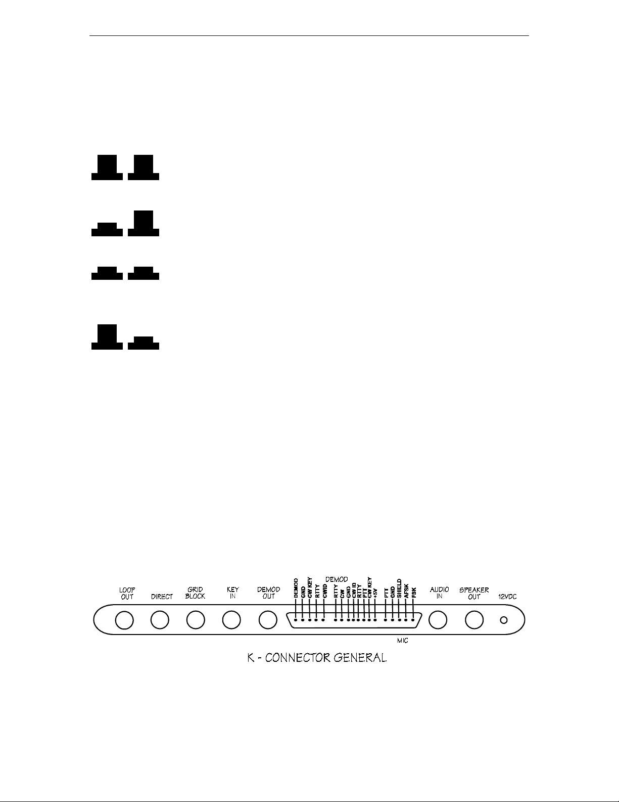
The next connector is a five pin jack, labeled K-connector because it is specifically
designed for use with KANTRONILCS software. From left to right the pins are as
follows:
DEMOD This pin produces the same output as the DEMOD OUT jack.
GROUND This pin provides the ground connections between the interface and the
computer.
CW KEY This input pin allows the computer to key the transmitter through the interface.
A low on this pin causes the interface to key the transmitter.
RTTY This input controls the AFSK for RTTY transmission. It works in conjunction
with CW ID signals and to operate the push-to-talk switch. This will be covered in detail
later.
CW ID This line controls the audio tone for CW identification. It works in conjunction
with the RTTY line to produced RTTY and CW ID signals and operate the push-to talk
switch. This will be covered in detail later.
3
Page 4

MFJ-1224 Instruction Manual RTTY/CW Computer Interface
Next is a eight pin general purpose connector which allows you to adapt the interface to
almost any computer and software. An internal DIP switch allows the inputs and outputs
to be inverted if necessary to correspond to the requirements of your computer. From left
to right, the pins are as follows:
RTTY DEMOD This output is a TTL version of a received RTTY signal.
GROUND This pin provides the ground connection between the interface and the
computer.
CW ID This input pin controls the shift for CW ID transmission.
RTTY This input pin controls the mark and space shift for RTTY transmission.
PTT This input controls the push-to-talk switch of the transmitter.
CW KEY This input controls the transmitter keying circuit.
+5VDC This input provides a 5 volt supply for external circuitry such as an RS-232
converter.
Next is a five-pin jack which is used for the microphone connection. From left to right,
the pins are as follows:
PTT OUT This pin is connected to the high side if the push-to-talk line. It is shorted to
ground to key the microphone.
PTT GROUND This pin is connected to the ground side of the push-to -talk line.
AFSK SHIELD This pin is connected to the ground for shield side of the AFSK line
AFSK OUT This line carries the audio signal for AFSK RTTY to the microphone input.
FSK OUT This line provides FSK signal for keying FSK rigs.
4
Page 5

MFJ-1224 Instruction Manual RTTY/CW Computer Interface
AUDIO IN The audio input jack should be connected to the external speaker jack or
headphone jack of your receiver with a shielded audio cable. The interface end of the
cable requires a RCA type plug.
SPEAKER OUT The speaker output jack may be connected to a speaker using shielded
audio cable. The interface end of the cable requires a RCA type plug.
12VDC The power jack requires 12VDC from a 2.5mm sub miniature plug with the tip
positive and the sleeve ground.
PRELIMINARY CONNECTIONS
Input and output signals must be TTL level (+5VDC and ground). Inputs are RTTY and
CW KEY(RTTY and CW on general purpose connector). There is also a separate CW ID
input for identifying in MORSE while operating RTTY. Outputs are DEMOD (RTTY
DEMOD and CW DEMOD on the GINERAL PURPOSE CONNECTOR) and DIRECT
and GRID BLOCK. Connections depend on the type of computer and transceiver used.
Either the GENERAL CONNECTOR or the K-CONNECTOR will be connected to the
computer.
CONNECTIONS
FOR CW
For transmission and reception of CW, the following connections are
necessary.
1.) A 12VDC power supply to the POWER jack of the interface.
2.) A shielded audio cable from the external speaker jack of the transceiver to the
AUDIO IN jack of the interface.
3.) If desired, a speaker may be connected to the SPEAKER OUT jack of interface.
4.) If the interface is to be used to key the transmitter by hand, the key should be
connected to the KEY IN jack.
5.) The control cable from the computer to the interface.
6.) A cable from one of the KEY OUT jacks of the interface to the KEY IN jack of
the transceiver. If you are not sure whether your transceiver requires GRID
BLOCK or DIRECT KEYING, try one and then the other to see which one works.
No damage will be done if the wrong one is selected.
5
Page 6

MFJ-1224 Instruction Manual RTTY/CW Computer Interface
FOR RTTY/ASCII For transmission and reception of RTTY or ASCII signals the
following connections are needed:
1.) A 12VDC power supply to the POWER jack of the interface.
2.) A shielded audio cable from the external speaker jack of the transceiver to the
AUDIO IN jack of the interface.
3.) If desired, a speaker may be connected to the SPEAKER OUT jack of the
interface.
4.) The microphone/PTT cable to the transmitter. This cable is supplied with the
proper push on the connector on one end and with the other end unwired. This
allows the cable to be connected properly for various types of transmitters. For
transmitters that have three wire microphone connectors; only three of the
microphone cables are needed. AFSK shield should be connected to ground ,PTT
should be connected to PTT OUT, and AFSK should be connected to ground at
the AUDIO INPUT. The FSK OUT is not connected when used for AFSK
operation.
Consult the owner's manual for your transceiver to determine the proper connection of the
MICROPHONE JACK. The white wire is the audio line, the red wire is the PTT line,
the black wire is the PTT ground line, the bare (shield) wire is the audio ground and the
green wire is the DSK line.
5.) The control cable from the computer to the interface.
6.) If the interface is to drive a TTY current loop. the TTY should be LOOP OUT
pin is usually connected to the negative side of your selector magnets.
INTERNAL CONTROLS
Caution: Improper adjustments of the internal controls will prevent the interface
from functioning.
The MFJ-1224 has several internal controls and adjustments, as shown in the diagram and
described below. The layout is shown in FIGURE 4.
AUDIO OUT GAIN
This controls the level of the audio for AFSK output. It is preset at
the factory to a reasonable level for most transmitters. Some adjustments may be
required if your transmitter requires a higher or lower setting. The best results usually
occur with high level from the interface and a low mic gain setting on the transmitter.
6
Page 7

MFJ-1224 Instruction Manual RTTY/CW Computer Interface
INPUT LEVEL It is very important that the input is set to the proper level for use with
your rig. First tune the radio until no signal is heard, (static only), then set the volume
slightly louder than your normal listening level. Turn the input level pot to the point
where the static does not cause any flickering of either the PHASE LOCK L.E.D. or the
DATA L.E.D.
OPERATION
SETTING UP THE MFJ-1224 FOR CW
COMPUTER OPERATION
Enter the program into your computer. Follow the directions provided with your
software. If using the Kantronics software, it will ask you to "PRESS K" for Kantronics
interface or "T" for user terminal unit. You must press "K". If you press "T", your
transmitted RTTY will be inverted.
TELETYPEWRITER OPERATION
If your radio teletype provides TTL voltages for input and output, you can hook it directly
to the MFJ-1224. If not, you will have to use the loop supply circuit and a current loop to
the TTL interfaces. (SEE CQ, November 1983, page 49.)
CW OPERATION
The MFJ-1224 uses it's Active RTTY filter to give selectivity for Morse signals and is
tuned to 2125Hz., one of the RTTY "High Tones"; considerably higher than usual 9001000Hz. In order to center your CW signal to the CW frequency of the station you are
working, some adjustment to your receiver's controls will be necessary.
7
Page 8

MFJ-1224 Instruction Manual RTTY/CW Computer Interface
MGJ-1224 CONTROL SETTING
1. Set the front panel switches on the MFJ-1224 as shown in Figure 3.
2. Tune the receiver until you hear only noise.
3. Turn the audio gain up to maximum.
4. Reduce RF gain for a comfortable listening level.
5. Remove the cover of the MFJ-1224.
6. Adjust the internal input level trimpot (next to the NORM/REV switch until the
PHASE LOCK L.E.D. and the DATA L.E.D. do not flicker with the audio input
(noise). (SEE Figure 4.)
Transceiver Settings:
SET: Mode to CW
X-tal to ON
RIT to OFF
IF-Shift to ZERO (Center)
Tune in the X-tal Cal as a Morse LO-Tone(900-1000Hz).
Turn ON the RIT.
Please do not touch the VFO.
Transceivers without CW Filters:
Adjust RIT for a higher pitch until the MFJ-1224's PHASE LOCK and DATA L.E.D.s
light. Finish the setting under the heading "FINISH."
Transceivers with CW filters, RIT and IF-SHIFT:
Adjust RIT for a higher pitch. Note that as the pitch goes up, the signal begins to move
out of the PASSBAND of the CW FILTER (S-Meter starts to fall). Using IF-SHIFT,
move the CW FILTER PASSBAND, keeping it over the signal (S-Meter UPSCALE).
Continue raising the pitch with the two controls also watching the MFJ-1224'S PHASE
LOCK and DATA L.E.D.s. When the L.E.D.s come on carefully adjust the RIT to center
the signal in the PASSGAND of the MFJ RTTY FILTER. Carefully adjust the IF-SHIFT
to center the signal in the PASSBAND of the transceiver's CW FILTER. Finish under the
heading "FINISH."
Transceivers with CW Filters, No If-Shift:
Switch to USB and adjust the RIT, as above, for "Transceivers without CW Filters." You
will receive and tune stations in the USB MODE, transmit in the CW mode. Finish the
setting under the heading "Finish."
8
Page 9

MFJ-1224 Instruction Manual RTTY/CW Computer Interface
Transceivers with CW Filters, No RIT:
Remove the CW FILTER so that the MORSE may be copied via the SSB FILTER. The
MFJ-1224 will provide the selectivity as needed for computer work. Proceed as per
"Transceivers without CW Filters."
Finish:
Log the settings of the CONTROL(S) for future reference. Turn the X-TAL CAL OFF.
With the controls of the MFJ-1224 set for CW, all Morse Tuning will be made with the
VFO. Your transmit signal will appear on the frequency to which the other station is
listening. If the transceiver has a digital display frequency counter, then your actual
transmit frequency will be displayed DURING TRANSMIT. Please resist any temptation
to adjust the RIT and IF-SHIFT from their "preset" positions.
CW TUNING
1. Tune the receiver to start at a low pitched tone, then progressively tune for a higher
pitch. As you tune higher in pitch, the following occurs:
A. The PHASE LOCK L.E.D blinks On and Off with the code.
B. Both PHASE LOCK AND DATA L.E.D.s blink On and Off
simultaneously.
C. Both L.E.D.s remain Off.
* IMORTANT *
The only correct tuning occurs at 'B' above when the PHASE
LOCK and the DATA LED's blink ON and OFF simultaneously
with the code.
When the PHASE LOCK and DATA L.E.D.s are blinking simultaneously with the code
and you don't see noise spikes triggering the L.E.D.s, the DEMOND out put will be low
(OVDC) for no tone and high (+5VDC) for a tone.
2. Look at your TV screen. The Morse should be followed correctly.
NOTE:
It may take several lines for the computer to start receiving the Morse correctly.
SETTING UP THE MFJ-1224 FOR RTTY
Tuning RTTY signals is much easier than tuning CW because reception is not affected so
much by noise. Since the signal is always present, noise does not have a chance to affect
the reception as in CW where the signal is absent for so much time. If adjustment for
CW has already been made, then adjustment for RTTY will probably not be necessary. If
9
Page 10

MFJ-1224 Instruction Manual RTTY/CW Computer Interface
the input level trimpot has not been adjusted, follow the procedure for CW, steps 1
through 6.
* CORRECT TUNING *
The only correct tuning occurs on RTTY is when the PHASE LOCK
is ON continuously and the DATA LED is blinking on and off the
most pronounced.
1. Set the switches on the MFJ-1224 for RTTY, 170 Hz shift, and NORMAL.
(See Fig. 3A.)
2. Set the computer for 60WPM RTTY. Most RTTY on the Amateur HF bands is
set at 60WPM, 170Hz shift.
3. Select an RTTY station on the receiver. The receiver should be LSB. Start tuning
from a low pitched tone to a high pitched tone. When the mark frequency of 2125Hz
is received, the PHASE LOCK L.E.D. is on.
4. Continue tuning until you see the most pronounced ON and OFF blinking of the
DATA L.E.D.
TO CALIBRATE
The MFJ-1224 Computer Interface is adjusted at the factory. However, should recalibration be necessary, here is the procedure for all frequency related devices in the
computer interface.
CALIBRATION OF THE PPL FREQUENCY
1. Set the MFJ-1224 Computer Interface to receive ASCII at 300 baud, 170Hz shift.
2. Record from AFSK Connector of the GENERAL PURPOSE CONNECTOR, two
minutes of "*" and "U" (Capital U) repeatedly on a tape recorder.
NOTE: The audio tone control should be set high.
10
Page 11

MFJ-1224 Instruction Manual RTTY/CW Computer Interface
3. Play the tape back into the audio input of the MFJ-1224.
4. Observe the flashing rate of the PHASE LOCK and the DATA L.E.D.s.
5. When the L.E.D. of the PHASE LOCK is on steadily, and the "*" and "U" is
occurring on the screen error free, the PLL frequency is at 2210Hz.
6. Turn the tab of the PLL trimpot until the PHASE LOCK L.E.D is on steadily, and the
data is running across the screen correctly. (SEE Figure 4.)
NOTE:
The DATA L.E.D. light will emit only while data flows. The PHASE LOCK
L.E.D. will emit steadily when the PLL frequency is correct. Indiscriminate
emission of the PHASE LOCK L.E.D. means that either PLL if off frequency or
that the audio level is too high, allowing coping of random noise.
CALIBRATION OF THE MARK FREQUENCY
1. Connect the computer or radioteletype control to the MFJ-1224.
2. All DIP switches in the 1224 should be OFF.
3. Turn the Interface On and set the front panel switches for RTTY, 170Hz shift, and
NORMAL polarity.
4. Enter the program into the computer. If using a radioteletype, go down to 8A.
5. If you are using Kantronics Hamsoft, press "K" when asked to choose "K" if using
a Kantronics Interface or T-User Terminal Unit.
6. Connect a frequency counter with a 1:00 probe to the AFSK output pin of the MIC
jack.
7. Go to the RTTY section of the program.
8. Put the computer into RTTY TRANSMIT with no characters in the buffer.
For Hamsoft, on the VIC-20 this is CTRL/T. Now go to 9.
8A. Put the radioteletype in the Mark condition (Loop Current Flowing).
9. Adjust VR2 trimpot (see Fig 4.) for a frequency of 2125Hz (+ 2Hz).
NOTE:
The MARK and SPACE frequencies must be set while the interface is
connected to the computer or radioteletype.
11
Page 12

MFJ-1224 Instruction Manual RTTY/CW Computer Interface
CALIBRATION OF 170Hz SHIFT
1. Put the computer into RTTY RECEIVE. For Hamsoft on the VIC-20.
2. Connect the frequency counter in the same manner as setting the MARK Frequency.
3. The counter should read 2295Hz.
4. If the counter doesn't read 2295Hz, then adjust VR3 (See Fig 4) for a reading of 2295
(+ 2Hz).
CALIBRATION OF THE 850Hz SHIFT
1. Set the MFJ-1224 front panel switches for 850Hz shift.
2. Connect a frequency counter as in Calibration of the MARK Frequencies.
3. The frequency counter should read 2975Hz.
4. If the counter doesn't read 2975Hz, adjust VR4 (See Fig. 4) for a reading of 2975Hz
(+ 2Hz).
SOFTWARE CONSIDERATIONS
DIP SWITCH
There is an eight switch DIP package on the PC board. These switches are used to
configure the inputs and outputs of the GENERAL PURPOSE CONNECTOR to work
correctly with your computer and software. The following chart illustrates functions of
each switch.
SWITCH POSITION FUNCTION SIGNAL AT PIN
1 ON CW KEY LOW-KEY
1 OFF CW KEY HIGH-KEY
2 ON CW ID KEY HIGH-CW-SHIFT
2 OFF CW ID TONE LOW-CW-SHIFT
3 ON KANTRONICS PTT N/A
3 OFF GENERAL PTT N/A
4 ON RTTY INPUT LOW MARK
4 OFF RTTY INPUT HIGH MARK
12
Page 13

MFJ-1224 Instruction Manual RTTY/CW Computer Interface
5 ON GENERAL PTT N/A
5 OFF KANTRONICS PTT N/A
6 ON PTT INPUT HIGH PTT
6 OFF PTT INPUT LOW INPUT
7 ON CW DEMOD OUTPUT LOW TONE
7 OFF CW DEMOD OUTPUT HIGH TONE
8 ON RTTY DEMOD OUTPUT LOW TONE
8 OFF RTTY DEMOD OUTPUT HIGH TONE
MFJ-1223 RS-232 INTERFACE
The MFJ-1223 is used to connect the MFJ-1224 ports. Since the MF-1224 to uses TTL
voltage (+ 5VDC) and RS-232 ports are + 12VDC, an interface becomes necessary to
interconnect. Our MFJ-1223 allows the use of the port.
I. VIC 20
A. Used with the MFJ-1252 or the MFJ-1264 Software.
NOTE: The connector cable supplied with the software has the proper connections
for the GENERAL CONNECTION PORT and the VIC USERS PORT. The DIP
switches are set at the factory for this computer, software, and cable.
MFJ-1224 General Connector User Port MFJ-1224 DIP Switches
RTTY DEMOD B, C, L 1 ON
CW DEMOD B, C, L 2 ON
GND N 3 ON
CW ID H 4 OFF
RTTY J, M 5 OFF
PTT (IN) NOT USED 6 OFF
CW KEY K 7 ON
+5VDC NOT USED 8 OFF
_____________________________________________________________________
B. Using Kantronics Hamsoft and Hamtext software.
NOTE
: The connector cable supplied with the software will connect directly between
the K CONNECTOR and the USERS PORT. The switches will have to be
set for use with this software.
13
Page 14

MFJ-1224 Instruction Manual RTTY/CW Computer Interface
MFJ-1224 "K" Connector
Control Port MFJ-1224 DIP Switches
DEMOD 6 1 OFF
GND 8 2 OFF
CW KEY 3 3 ON
RTTY 2 4 OFF
CW ID 1 5 OFF
6 OFF
7 OFF
8 OFF
_____________________________________________________________________
C. Using RAK Electronics RTTY / CWII Software
NOTE:
The DIP switches must be set for this software as follows:
MFJ-1224 General Connector
User Port MFJ-1224 DIP Switches
RTTY DEMOD B, C, 1 ON
CW DEMOD D 2 ON
GND 1 3 OFF
PTT J 4 OFF
RTTY M 5 ON
PTT (IN) NOT USED 6 OFF
CW KEY K 7 ON
+5VDC NOT USED 8 OFF
II. C-64
A. Using the MFJ-1265 or MFJ 1253 Software.
NOTE:
The connector cable supplied with the software has the proper connections
for the GENERAL CONNECTION PORT and the C-64 USERS PORT.
The DIP switches are set at the factory for this computer, software, and
cable.
MFJ-1224 General Connector User Port MFJ-1224 DIP Switches
RTTY DEMOD B, C, L 1 ON
CW DEMOD B, C, L 2 ON
GND N 3 ON
CW ID H 4 OFF
RTTY J, M 5 OFF
PTT (IN) NOT USED 6 OFF
CW KEY K 7 ON
+5VDC NOT USED 8 OFF
14
Page 15

MFJ-1224 Instruction Manual RTTY/CW Computer Interface
_____________________________________________________________________
B. Using Kantronics Hamtext Software
NOTE:
The DIP switches must be set for this software as follows:
MFJ-1224 "K" Connector
Control Port MFJ-1224 DIP Switches
DEMOD 6 1 OFF
GND 8 2 OFF
CW KEY 3 3 ON
RTTY 2 4 OFF
CW ID 1 5 OFF
6 OFF
7 OFF
8 OFF
_____________________________________________________________________
C. Using the AEA-SOFT and MBA-TEXT, VERSION 1.2 Software
NOTE:
The DIP switches must be set for this software as follows:
MFJ-1224 General Connector
User Port MFJ-1224 DIP Switches
RTTY DEMOD J 1 ON
CW DEMOD J 2 ON
GND 1, 12, A, N 3 OFF
CW ID NOT USED 4 ON
RTTY F 5 ON
PTT (IN) E 6 OFF
CW KEY H 7 OFF
+5VDC NOT USED 8 OFF
_____________________________________________________________________
III. APPLE
A. Using the C. H. GALFO Software
NOTE:
The DIP switches must be set for this software as follows:
MFJ-1224 General Connector
Apple Game Port MFJ-1224 DIP Switches
RTTY DEMOD 2 1 ON
CW DEMOD 4 2 ON
GND 8 3 OFF
CW ID NOT USED 4 OFF
RTTY 15 5 ON
PTT (IN) 14 6 ON
CW KEY 13 7 ON
15
Page 16

MFJ-1224 Instruction Manual RTTY/CW Computer Interface
+5VDC NOT USED 8 ON
B. Using Kantronics Hamsoft Software
NOTE:
The DIP switches must be set for this software as follows:
MFJ-1224 "K" Connector
Apple Game Port MFJ-1224 DIP Switches
DEMOD 3 1 OFF
GND 8 2 OFF
CW KEY 14 3 ON
RTTY 12 4 OFF
CW ID 13 5 OFF
6 OFF
7 OFF
8 OFF
C. Using the AEA-Software
NOTE:
The DIP switches must be set for this software as follows:
MFJ-1224 General Connector
Apple Game Port MFJ-1224 DIP Switches
RTTY DEMOD 2 (PBO) 1 ON
CW DEMOD 4 (PBO) 2 ON
GND 8 GND 3 OFF
CW ID NOT USED 4 OFF
RTTY 15 (ANO) 5 ON
PTT 14 (AN1) 6 OFF
CW KEY 13 (AN2) 7 OFF
+5VDC NOT USED 8 ON
_____________________________________________________________________
IV. TRS-80 COLOR COMPUTER
A. Using the Kantronics Software.
NOTE:
The DIP switches must be set this software as follows:
MFJ-1224 "K" Connector Hamsoft Pac MFJ-1224 DIP Switches
DEMOD DEMOD 1 OFF
GND GND 2 OFF
CW KEY CW KEY 3 ON
RTTY RTTY 4 OFF
CW ID CW ID 5 OFF
6 OFF
7 OFF
8 OFF
16
Page 17

MFJ-1224 Instruction Manual RTTY/CW Computer Interface
B. Using Clay Abrams Software.
NOTE:
The DIP switches must be set for this software as follows:
MFJ-1224 General Connector Serial I/O (P2) MFJ-1224 DIP Switches
RTTY DEMOD PIN 2 1 OFF
CW DEMOD PIN 2 2 ON
GND PIN 3 3 OFF
CW ID NOT USED 4 OFF
RTTY PIN 4 5 OFF
PTT (IN) NOT USED 6 OFF
CW KEY PIN 4 7 OFF
+5VDC NOT USED 8 ON
NOTES:
1. A TTL TO RS-232 CONVERTER MUST BE USED WITH THE CLAY
ABRAMS SOFTWARE.
(We recommend the MFJ-1223.)
2. PLACE A luf ELECTRONIC CAPACITOR FROM PIN 2 (DATA IN) OF
THE SERIAL I/O TO GROUND.
Hamsoft and Hamtext are trademarks of Kantronics, Inc.
VIC-20 is a trademark of Commodore Business Machines, Inc.
TRS-80 Color Compute is a trademark of Tandy Corporation.
17
Page 18

MFJ-1224 Instruction Manual RTTY/CW Computer Interface
TECHNICAL ASSISTANCE
If you have any problem with this unit first check the appropriate section of this manual.
If the manual does not reference your problem or your problem is not solved by reading
the manual, you may call MFJ Technical Service at
601-323-5869
. You will be best helped if you have your unit, manual and all information
601-323-0549
or the MFJ Factory at
on your station handy so you can answer any questions the technicians may ask.
You can also send questions by mail to MFJ Enterprises, Inc., 300 Industrial Park Road,
Starkville, MS 39759; by Facsimile (FAX) to 601-323-6551; or by email to
techinfo@mfjenterprises.com. Send a complete description of your problem, an
explanation of exactly how you are using your unit, and a complete description of your
station.
18
 Loading...