

Page 1

MFJ-1214-PC Multimode
INTRODUCTION
MFJ-1214PC
MULTIMODE COMPUTER INTERFACE
INSTRUCTION MANUAL
MFJ Enterprises, INC
300 Industrial Park Road
Starkville, MS 39759 USA
Copyright 1996 No one may copy or reproduce any part of this
document without the express permission of MFJ Enterprises, INC.
Printed in USA.
Table of Contents
•INTRODUCTION
Multi-Mode Computer Interface
1-1
Page 2

MFJ-1214PC Multimode ,
INTRODUCTION
Unpacking your 1214PC
1-2
System Requirements
1-3
Hardware Installation
1-4
Radio Interfacing
1-6
HT Interfacing 1-6
Transmit Audio Level
1-6
Cabling Accessories
1-7
MFJ-1272 Mic Switch 1-7
Software Installation
1-8
Formatting New Disks
1-8
Disk Backup
1-10
Installing the 1214PC Software
1-11
SYSTEM SETUP
MFJ-1214PC Main Menu
2-1
Step-by-Step System Setup
2-2
Graphics Configuration
2-3
Video Mode
2-3
X Size
2-4
Y Size
2-4
EGA or VGA
2-5
Super VGA Chipset Selection
2-5
Test 2-7
Auto 2-7
Serial Port Selection
2-8
COM 1-4 2-8
Int 1-4
2-8
Auto 2-8
Printer Port Selection
2-9
LPT 1-3 2-9
II
Page 3

MFJ-1214PC Multimode ,
INTRODUCTION
Remaining Options
2-9
VGA Enhancer 2-9
DMA 2-9
Save 2-10
Exit 2-10
Quick Screen Redraw
2-10
FREQUENCY MANAGER
Frequency Manager
3-1
Frequency Manager Commands
3-2
New 3-2
Edit 3-3
Save Frequency List
3-4
Reduce Frequency List
3-4
Print Frequency List
3-5
Exit 3-6
FAX OPERATION
Fax Operation
4-1
Description of a FAX
4-1
Sending and Receiving FAX
4-2
File Manager Commands
4-3
Transmit 4-4
Configuration
4-5
Transmit File
4-6
Transmit Screen
4-6
Exit 4-6
Receive 4-7
Status Box
4-7
Skew Right
4-8
Skew Left 4-8
Manual Synchronization
4-8
III
Page 4

MFJ-1214PC Multimode ,
INTRODUCTION
Normal Inverse 4-8
Engage Autosave
4-9
Engage Autoprint
4-9
Mark End Of Picture
4-9
Exit 4-9
Hauto
4-10
Mauto
4-10
RX Adjust 4-11
Receiving Tip
4-11
Tuning To A FAX Signal
4-12
Bandwidth Control
4-13
Start Frequency
4-14
Stop Frequency 4-14
Special Parameters
4-15
Use Start Frequency
4-15
Inverse Phasing
4-15
MFJ/BMET/NSK 4-16
Chan1, Chan2
4-16
H Mirr
4-16
V Mirr
4-16
Inverse
4-16
SW 5% 4-16
Exit 4-16
Timer Reception
4-17
Start at
4-18
Stop at
4-18
Exit 4-18
Auto Functions 4-19
Autosave 4-19
Disk Save Format
4-19
IV
Page 5

MFJ-1214PC Multimode ,
INTRODUCTION
Auto Print
4-20
Set Menu Color 4-21
Nice 4-22
Y Geo
4-22
267, 288, 352, 576
4-22
48, 60, 90, 120, 180, 240
4-23
Load FAX 4-23
Save FAX 4-24
Color Processing
4-24
Delete
4-25
Rename 4-25
BInfo
4-25
Display FAX
4-25
Global Display 4-26
Load 4-26
Rename 4-27
Delete
4-27
Exit 4-27
Print Fax 4-27
Printer Control
4-27
Configuration
4-30
Receiver Control String
4-30
Baudrate 4-30
Load 4-31
Save 4-31
Exit 4-31
Animate FAX
4-31
Create Animation
4-32
Show Animation 4-32
Exit 4-32
Picture Rotation
4-32
90 Rotation
4-32
180 Rotation
4-33
V
Page 6

MFJ-1214PC Multimode ,
INTRODUCTION
270 Rotation
4-33
Exit 4-33
Step-by-Step: How To Receive A FAX
4-34
Step-by-Step: How To Transmit A FAX
4-36
COLOR FAX
Color FAX 5-1
Standards for Color FAX
5-1
Create Color FAX
5-1
Cyan 5-2
Magenta 5-2
Yellow
5-3
View Picture
5-3
Load Picture
5-3
Extract Functions
5-4
Define Extract
5-4
Mouse
5-4
Enter
5-5
F10 5-5
Extract Screen
5-5
Full Screen
5-5
Display Full
5-5
Load Extract Definition
5-5
Save Extract Definition
5-5
Display Functions
5-5
Mirror Picture
5-5
Synchron Picture
5-6
Invert Picture
5-6
Display Extract
5-6
VI
Page 7

MFJ-1214PC Multimode ,
INTRODUCTION
Set Color Palette
5-6
Color Work
5-7
Define Color Point
5-7
Save Color Point
5-7
Escape to Picture
5-7
Tab to Main Menu
5-7
Save Picture
5-7
Delete
5-8
Rename 5-8
Binfo
5-8
90 Rotation
5-8
180 Rotation
5-8
270 Rotation
5-8
Print Picture
5-8
Setup Printer
5-8
Cyan Sequence 5-8
Magenta Sequence
5-8
Yellow Sequence
5-9
Intensity 5-9
Saturation
5-9
256 Color Picture
5-9
3600 Color Picture
5-9
4096 Color Picture
5-10
True Gray Picture
5-10
32K Color Picture
5-10
Save IFF 24 Bit
5-11
Nice Mode 5-11
Exit 5-11
VII
Page 8

MFJ-1214PC Multimode ,
INTRODUCTION
Step By Step: How to Create a Color FAX
5-12
RTTY/ASCII OPERATION
System Setup for RTTY
6-1
Standards for RTTY Transmit and Receive
6-1
RTTY/ASCII Receive
6-2
Auto Converter 6-4
Full ADC Range 6-4
Auto ADC Adjust
6-4
Lo Level 6-5
Mi Level 6-5
Hi Level 6-5
RTTY Transmit 6-5
Tx All
6-5
Tx Cur
6-5
Text Editor
6-6
Editor Functions and Commands
6-6
TX All
6-7
TX Cur 6-7
Load Text 6-7
Save Text 6-9
Delete Line
6-9
Delete Text
6-9
Insert Text
6-10
Exit 6-10
Editor
6-10
Screen
6-10
PgUp PgDown 6-10
Home
6-10
End 6-10
CW OPERATION
Standards for CW Reception and Transmission
7-1
CW Tuning Procedure 7-1
VIII
Page 9

MFJ-1214PC Multimode ,
INTRODUCTION
CW Transmission
7-4
TX All
7-5
TX Cur 7-5
CW/RTTY/ASCII FUNCTIONS
Mode 8-1
Edit 8-1
Clr 8-1
Baud 8-1
Normal /Inverse
8-3
LE/FI
8-3
Save 8-3
Save Buffer Only
8-4
Save Buffer
8-4
Save Current
8-5
Print
8-5
Adjust
8-5
Analyzer 8-6
TX Params 8-6
Speaker 8-7
QRM Mode 8-7
Synchronous Mode
8-7
Accept
8-7
Cancel
8-7
Mark 8-8
Space
8-8
RX Params 8-8
Mark And Space 8-9
Space Only
8-9
Exit 8-9
Mode Configurations
8-9
Load Configurations
8-9
Save Configurations
8-10
IX
Page 10

MFJ-1214PC Multimode ,
INTRODUCTION
Timer
8-12
Start
8-12
Stop 8-12
APPENDIX
Radio Hookup
A-1
Radio Port Connection
A-2
Hex To Decimal Conversion Chart
A-3
Troubleshooting
A-4
Order Form
A-5
LIST OF FIGURES
Fig. 1-1 9/25 Pin Configuration Jumper
Fig. 1-2 Grid Block/Direct Jumper
Fig. 2-1 VT Menu
Fig. 2-2 Configuration Screen
Fig. 2-3 Good Chip Set Selected
Fig. 2-4 Bad Chip Set Selected
Fig. 2-5 Testing Serial Ports
Fig. 2-6 Serial Test Port Complete
Fig. 2-7 Save Modifications Screen
Fig. 3-1 Frequency Manager Menu
Fig. 3-2 Enter Frequency Menu
Fig. 3-3 Stations Conditions Menu
Fig. 3-4 Print Frequency List Menu
Fig. 4-1 FAX Components
Fig. 4-2 Transmit Receive Fax Screen
Fig. 4-3 Transmit Selection Screen
Fig. 4-4 Statis Box
Fig. 4-5 Bar Graph
Fig. 4-6 Two Level Tuning Graph
Fig. 4-7 Multi Level Tuning Graph
Fig. 4-8 Special Parameters Menu
Fig. 4-9 Timer Menu
Fig. 4-10 Set Menu Color Menu
Fig. 4-11 Load Fax File Manager
Fig. 4-12 Save Fax File Manager
Fig. 4-13 Global Display Menu
Fig. 4-14 Scaling Examples
Fig. 4-15 Dither Example
X
Page 11

MFJ-1214PC Multimode ,
INTRODUCTION
Fig. 4-16 Floyd Example
Fig. 4-17 Animation Selection Menu
Fig. 5-1 Color Fax Menu
Fig. 5-2 Extract Menu
Fig. 6-1 RTTY Character "D"
Fig. 6-2 ASCII Character "S"
Fig. 6-3 RTTY Tuning Indicator Receiving
Fig. 6-4 Load Editor Text Menu
Fig. 6-5 Save Editor Text Menu
Fig. 7-1 Mode Select Menu
Fig. 7-2 Receive Parameters Menu
Fig. 7-3 Transmit Parameters Screen
Fig. 8-1 Baud Rate Select Table
Fig. 8-2 Select WPM
Fig. 8-3 Save Options
Fig. 8-4 Tuning Indicator
Fig. 8-5 Transmit Parameters
Fig. 8-6 Receive Parameters
Fig. A-1 5 Pin Din Wire Colors
LIST OF TABLES
Table 2-1 Video Modes
Table 2-2 Graphics Modes For Specific Chipsets
Table 4-1 Printer Drivers
Table A-1 Mic Cable Wiring
Table A-2 Radio Cables
Table A-3 Decimal to Hexadecimal Conversion Table
XI
Page 12

MFJ-1214PC Multimode ,
INTRODUCTION
Important Notes
Hardware Compatibility
This new software is specifically for the New Model MFJ-1214
Rev. 4. This unit has expanded functions to work with this
software which older MFJ-1214's do not have. If you own an
older MFJ-1214 and use this software MFJ does not guarantee it's
compatibility.
Keyboard Conventions
Due to the lack of standardization for IBM-PC Compatible
keyboards it is necessary to standardize keystroke instructions
in this manual. The following chart tells how this instruction
will denote different keystroke for all keyboards.
Manual
Text
<ENTER>
Press the Enter Key after tying in the
BackSpace
Del
Insert
Home
End
PgUp
PgDown
Ctrl
Press and Hold Ctrl, Press and Release another
Alt
Press and Hold Alt, Press and Release another
Keystrokes for all keyboards
The Enter Key: Enter: Return or A large key
with a bent arrow
preceding text
The Back Space Key: BackSpace or the Straight
Arrow above Enter
The Delete Key: Delete, Del, or . Del (must
have Num Lock OFF)
The Insert Key: Insert or 0 Ins (Num Lock
OFF)
The Home Key: Home or 7 Home (Num Lock OFF)
The End Key: End or 1 End (Num Lock OFF)
The PageUp Key: Page Up, PgUp or 9 PgUp (Num
Lock OFF)
The PageDown Key: Page Down, PgDn or 3 PgDn
(Num Lock OFF)
The Control Key: Ctrl or Control
Key, Release Ctrl
The Alternate Key: Alt
Key, Release Alt
XII
Page 13

MFJ-1214PC
MULTI-MODE COMPUTER INTERFACE
We here at MFJ would like to welcome you the world of FAX, with
your purchase of the MFJ-1214PC Multi-Mode Computer Interface.
The MFJ-1214PC Multi-Mode Computer Interface, along with the
software is one of the most advanced FAX interfaces available
today. The MFJ-1214PC connects between a transceiver (or a
receiver) and an IBM or compatible computer. The package comes
complete with the MFJ-1214PC Multi-Mode Interface, 1214PC
software, a power supply, and cables (no connector provided for
the microphone input on the radio).
The 1214PC software was developed primarily for the reception
and transmission of FAX pictures and data. In FAX mode, priority
was given to picture quality when received. The full
capabilities of the program become apparent only when the
program is run on a fully compatible computer. Please refer to
the System Requirements section of this manual for further
details.
Using the FAX mode, the MFJ-1214PC is capable of receiving and
transmitting both color FAX with up to 256 colors, using a
standard VGA graphics card. Reception of FAX pictures, with
3600, 4096 or 32000 colors is possible, with a graphics system
capable of 24-bit graphics. Pictures can also be received in
black and white FAX in 16 gray levels. Using the text mode, the
1214PC is capable of receiving and transmitting Baudot (RTTY),
ASCII, and CW.
The Fast-start manual provided gives you some basic information
so that you can get the MFJ-1214PC up and running in a minimum
amount of time. Detailed operation is given in the MFJ-1214PC
Instruction Manual.
The software is composed of several separate programs that are
accessed through a menu driven shell. Most of the individual
programs have their own parameter files. This allows the user to
alter the software to suit his/her needs. These parameters files
contain things like baud rate for RTTY, picture resolution in
FAX mode, and operating speed in the CW mode. This allows the
program to come up the same way every time it is loaded.
132
Page 14

Unpacking Your MFJ-1214PC
Before we get into the System Requirements section let's unpack
your MFJ-1214PC.
NOTE: Be careful when unpacking your MFJ-1214PC to make sure
you do not lose any of the items!
Upon opening the packing carton, check to make sure that your
MFJ-1214PC Package includes the following items:
MFJ-1214PC Hardware Interface
MFJ-1214PC Program Disks (1) DSHD 3.5 or 5.25 Disks **
Serial Cable (DB-25 Male to Female)
(DB-9 Serial Cable Upon Request)
Comprehensive Instruction Manual
Fast-Start Guide
Open-ended Radio Port Cable
AC Adapter (12 VDC)
NOTE: Check to make sure your MFJ-1214PC Package is complete.
Once you have done this, you are ready to begin
installing your new MFJ-1214PC. The hardware should be
installed first and then the software. Please follow the
instructions for installation carefully.
Now why don't we get into the computer System Requirements for
the different modes of operations.
** If your computer does not have high density disk drives
refer to the order form in the Appendix to order another size.
142
Page 15

System Requirements
The program is either mouse and or keyboard driven. To change any
field in the program, either "click" the mouse on the field or
press the related keyboard key.
A hard drive will be required to install the 1214PC software.
The larger and faster that a hard drive is the better. FAX file
on average are larger than 800KB. Obviously just a few FAX files
will take a lot of hard drive space.
If you have a 9-pin serial port, you will need a 25 pin to 9 pin
adapter. If you do not have one, MFJ will exchange a 25 pin to 9
pin cable for the standard cable we sent you, at no charge.
CW/RTTY/ASCII
Below is a list of requirements for running the 1214PC software
in ONLY CW, RTTY or ASCII.
* XT or above IBM PC Compatible Computer
* 8 MHz or faster
* 640Kb of Memory (Minimum
Requirement)
* VGA or EGA graphics, (VGA Highly Recommended)
* Hard Drive (40 Mb or Higher
Recommended)
* RS-232 serial port (COM 1,2,3, or
4)
* 1.2MB 5.25" or 1.44MB 3.25" Floppy Disk Drive
FAX
For running FAX you must also meet the following requirements
* IBM 286, 386, or 486 IBM PC Compatible Computer
* 10 MHz or faster
* VGA
In order to operate and take full advantage of the MFJ-1214PC
graphics capabilities for FAX graphics you must have VGA
capability. The graphics requirements needed to operate the TEXT
modes (RTTY, ASCII and CW) are not as critical.
If you wish to run the program on a Laptop you must have VGA, even
with a monochrome display.
NOTE: If your computer does not meet these requirements you
can order a suitable program to control your 1214 from
MFJ. Refer to page 5 in the Appendix for an order form.
152
Page 16
Hardware Installation
The first step needed to set up the MFJ-1214PC is to connect it
from the computer to your radio. Please follow the steps below to
ensure a safe and quick installation process:
1. Ensure that the POWER switch for the computer is in the OFF
position.
2. Ensure that the POWER switch on the MFJ-1214PC is in the OFF
or (out) position.
3. Insert the 2.1mm coaxial plug from the AC adapter supplied
into the Power Jack (J2) on the back of the MFJ-1214PC.
NOTE: For a 220 or 240 V wall outlet, you will need to use an
AC Adapter that provides 12V DC @ 300 mA. Wire the 2.1mm
plug with the inner sleeve positive and the outer sleeve
to ground. If you do not have such an adapter, the MFJ1315x 220/240 VAC is available as an optional accessory.
4. Connect the male end of the serial cable to the RS-232
serial port (J3), on the back panel of the MFJ-1214PC.
5. Connect the female end of the serial cable to the serial
port, COM1, 2, 3, or 4 on the back of your computer. If you
have a 9-pin serial port, MFJ will exchange your 25-pin
cable for a 9-pin cable.
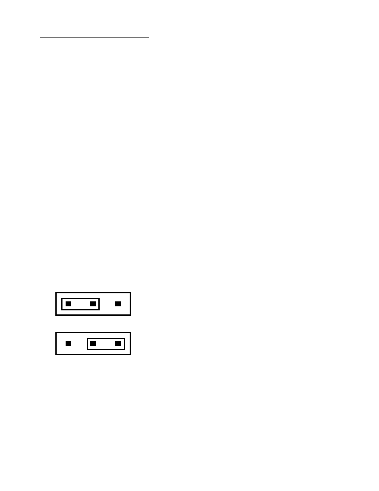
6. If you wish to use a 9-pin serial cable at the back of your
computer, change the jumper (J6) at the back of the MFJ1214PC to position 9 as shown below. If not, leave jumper
(J6) at position 25 as shown below.
25 9
25 Pin Configuration
25 9
9 Pin Configuration
Fig 1-1 9/25 Pin Configuration Jumper
162
Page 17
7. Wire the open-end of the radio cable provided in your MFJ-
1214PC package to a connector that matches your transceiver
mic input. If you have a communications receiver, then wire
a cable from the AUDIO INPUT (J7) on the MFJ-1214PC, to the
speaker output on your receiver. The AUDIO INPUT jack (J7)
is an RCA connector. Wire the center conductor of the RCA
plug "HOT", and the outside conductor to "GROUND". Follow
the Table A-1 in the Appendix to see which wires go where.
To purchase a pre-wired cable from MFJ see Table A-2 in the
Appendix for the appropriate cable.
8. Once the your radio interface cable is wired properly,
connect the round, 5-pin DIN connector of the mic cable to
the radio port J1 on the back of the MFJ-1214PC. The round
end of the 5-pin cable is KEYED, so the cable can only be
plugged in on way.
9. A shielded cable will be needed for transceiver keying in
the CW mode. The cable will be connected from the CW KEY
jack (J4), to the key input on the back of you transceiver.
The CW KEY jack (J4) in an RCA connector. When you wire the
shielded cable, wire the center conductor "HOT", this would
be the insulated wire in the cable. Wire the outside of the
RCA connector to the "GROUND", this would be the "BARE" wire
in the cable.
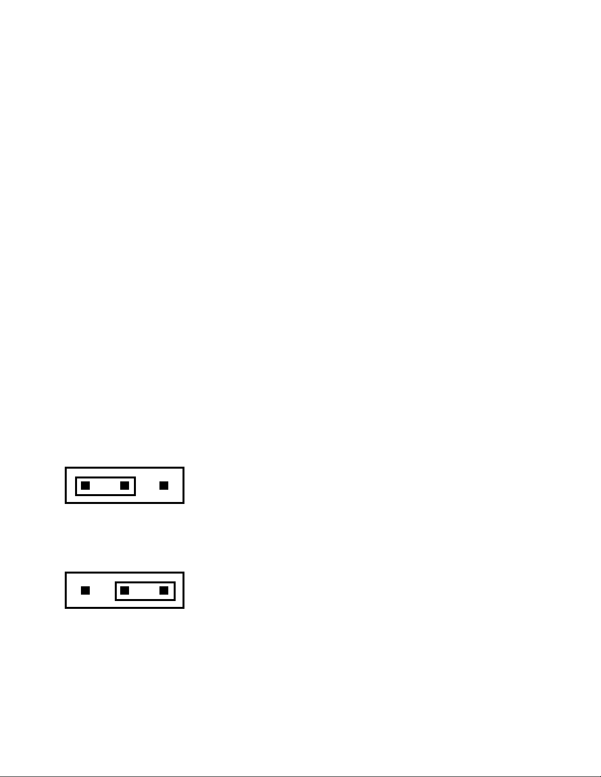
10. The GRID BLOCK/DIRECT jumper (J5) comes configured for
DIRECT keying. This will be sufficient for late model ICOM,
KENWOOD and YEASU radios. If you intend to use this with an
older model grid block keyed radio, just re-position (J5)
for GRID BLOCK keying. Locate jumper J5 on the PCB in front
of the 5 pin DIN jack. Move the jumper to the two pins
closest the "G". Please see the diagrams below:
D
G
GRID BLOCK/DIRECT Jumper (J5) configured for Direct Keying
D
GRID BLOCK/DIRECT Jumper (J5) configured for Grid Block Keying
Fig 1-2 Grid Block Direct Jumper Diagram
G
172
Page 18
Radio Interfacing
The first step in interfacing your radio to the MFJ-1214PC, is
to wire the 5-pin DIN cable to your microphone input. This can
also be wired to an accessory port on the radio. Please refer to
Page 10 for pin assignments and Page 11 for wire colors of the
5-pin DIN cable.
Once the 5-pin DIN cable is wired properly, connect the DIN end
(round end), to the radio port (J1), on the back panel of the
MFJ-1214PC. The other end of the DIN cable should be connected
to microphone input on the radio. As mentioned earlier you can
connect it to an external accessory port on the back of the
radio. This will enable you to keep the microphone and the
interface connected at the same time. Another alternative is to
use the MFJ-1272B TNC/MICROPHONE switch.
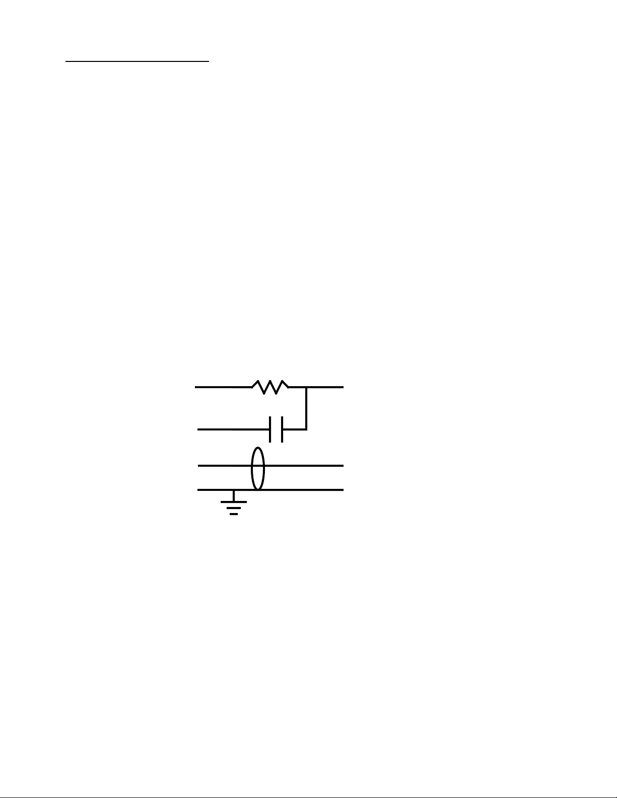
HT Interfacing
Most HT's make the PTT circuit by conducting current on the same
input pin as the TX Audio. If this is true for your HT, then you
will need to install a capacitor and also a resistor as shown
below:
5 Pin Din Ht Connections
R
PTT
Pin 3
TX Audio
Pin 1
C
Rec Audio
Pin 4
Ground
Pin 2
R - 2.2 - 3.3 K Ohm
C - 0.1 µF
Fig F-3 HT Keying Circuit
Transmit Audio Level
In order for the MFJ-1214PC to operate efficiently with your
particular radio, you will need to adjust the transmit audio
level, from the MFJ-1214PC to the radio. The following
equipment is needed to perform this adjustment:
Mic Audio
Speaker Out
Ground
182
Page 19

Transceiver-- This is the radio which you are going to interface
with the MFJ-1214PC.
Receiver--This receiver should receive the frequency
transmitted from the Transceiver.
Small Flat-Tip Screwdriver-- This will be used for adjusting R36
inside the MFJ-1214PC.
With all of the necessary equipment at hand, please perform the
following procedure:
1. Connect the radio to a dummy load and listen to the
transmission with the receiver.
2. Remove the cover from the MFJ-1214PC unit. Set the screws
aside so they do not get lost.
3. Load the RTTYII.EXE program and go into the transmit mode.
This is done through the Editor, using the F1 or F2 key
functions.
4. With the small flat-tip screwdriver turn R36 all the way
counter clockwise.
5. Adjust R36 clockwise until no increase in audio level is
detected on the receiver. Do not go beyond this point, to
prevent distortion of your transmitted signal.
Once you have adjusted the transmit audio level properly, you
are then ready to operate the MFJ-1214PC.
Cabling Accessories
Here are some cables which are available from MFJ. These cables
are listed in Table A-2 in the Appendix.
MFJ-5082, open end cable with 8-pin microphone plug
MFJ-5224, open end cable for ICOM/YAESU handhelds
MFJ-5226, open end cable for KENWOOD handhelds
MFJ-5268, open end cable with Modular telephone plug
(YAESU FT-2400, KENWOOD TM641A, TM741A, TM732A)
MFJ-1272B Mic Switch
The MFJ-1272B Microphone Switch will eliminate the frustration
involved in changing cables (both mic and receive audio) when you
switch from the MFJ-1214PC to your microphone.
Call 1-800-647-1800 to order any of the above or use the order
form on page A-5.
192
Page 20

Software Installation
This is the Software Installation section of the MFJ-1214PC
manual. If you are this far into the manual, this means that you
have completed the Hardware Installation section. This should
mean that everything in relation to the MFJ-1214PC such as
cables, power supply besides software is all finished. Right??
If you have any doubts, go back and double-check everything from
the introduction up to this point.
Now that you have DOUBLE CHECKED everything to this point, let's
get right into Software Installation.
Before installing the 1214PC software, make a copy of the
original disk. The software comes either a high-density 1.2MB,
5.25" or 1.44 MB, 3.5".floppy disks. You must copy the disks to
a high density disk of the same size as your installation disks.
If you know how to copy a disk proceed to the section Installing
the 1214PC Software, after you have made a backup of the
installation disk. Otherwise, please follow the steps in the
sections carefully and precisely.
Formatting New Disks
To make a copy of the original, you must first FORMAT a new
floppy disk. PLEASE FOLLOW THE STEPS BELOW CAREFULLY!! Whenever
formatting a new floppy disk great care must be taken. You could
erase disk files on a disk which you do not want to erase! Below
are steps for formatting a new floppy disk.
1. Ensure the computer is turned OFF.
2. Turn your computer ON and allow it to BOOT UP and present
the DOS prompt (either A: or C:) on your computer screen .
NOTE: Whenever <ENTER> is used this means to press the ENTER or
RETURN key on your keyboard.
3. Once the DOS prompt is on your screen, please type one of
the following:
FORMAT A: <ENTER> if your A: drive has the same
FORMAT B: <ENTER> if your B: drive has the same
NOTE: You may have to change to the DOS directory if it is not
specified in your path.
CD DOS <ENTER>
size disk as the 1214PC
software
size disk as the 1214PC
software
202
Page 21

If the FORMAT.COM file exists on your disk, the computer
will display the following message:
Insert new diskette for drive A: ( or B:)
and press ENTER when ready....
NOTE: The floppy disk used in step #5 must be of compatible
type to the 1214PC software disks. If not, the backup
will not be complete.
4. When the above message appears on the screen, remove any
disk from the drive and insert the new disk into the drive
to be formatted and press Enter. The disk you insert should
be of the "BRAND NEW NEVER BEEN USED" brand. If not, you
risk the loss of all data on the disk you insert.
5. When the new floppy disk is finished formatting, the
computer will ask you to NAME the disk. If you want to name
it type the NAME at the prompt. If not, then just press the
Enter key.
6. After the computer has written the NAME you typed to disk,
you will be prompted with the question:
FORMAT ANOTHER (Y/N)?
If you have no other disks to format press the N key then
Enter. If so, then press the Y key then Enter and the
format process will start over again.
This completes disk formatting. If further help is needed on this
operation, please refer to your DOS manual.
212
Page 22

Disk Backup
If you are reading this, then everything must have gone well to
this point. If not, then go back and double check and make
everything right up to this point.
Well here we go into the process of making a copy of the original
disk for the MFJ-1214PC.
The easiest way is to copy a disk is to use the DOS program
called DISKCOPY.COM. Please follow the procedure below to use
DISKCOPY:
1. Remove any floppy disks presently in your floppy drive.
2. To execute the DISKCOPY.COM type:
DISKCOPY A: A: <ENTER> if your A: drive has the
same size disk as the 1214PC
software
DISKCOPY B: B: <ENTER> if your B: drive has the
same size disk as the 1214PC
software
3. You will be prompted to insert the SOURCE disk into Drive (A
or B). Insert the original MFJ-1214PC program disk and
press Enter.
4. After the computer has read the files from SOURCE disk, you
will be prompted for the TARGET disk. Insert the TARGET
disk into the same drive and press the Enter key. The
computer will then start writing the files it read off of
the source disk to the TARGET disk.
The computer may ask for the SOURCE disk more than once. Repeat
steps #3 and #4 until the disk copy process is complete.
When the copy process is finished the computer will ask you if
you wish to make another copy. If so, then answer the question by
pressing the Y key along the Enter key. Then repeat steps #3 and
#4 for each disk to be copied. If not, then answer the question
with an N and press Enter.
If everything has gone well to this point then you are finished
making a copy of the original MFJ-1214PC program disk. Do not
put a write-protect tab on the disk you just copied. The software
needs to write data to disk during certain operations. Take the
original program disk and put it in a safe place, free of dirt,
dust, heat, moisture and away from magnetic fields.
The above example is only one of many ways of making a copy. If
you need further help, please refer to your DOS system manual.
Now lets proceed the software installation.
222
Page 23

Installing the 1214 Software
This section will show you how to install the MFJ-1214PC software
on a computer equipped with a hard drive. Basically, our install
programs are going to uncompress and copy all files from the
working copy of the disk to the hard drive. Please follow the
steps below:
1. Set your computer power switch to the ON position, and allow
the computer to "boot up".
2. Once the computer has booted up, and you have your DOS
prompt type:
C: <ENTER>
CD \ <ENTER>
This changes the hard drive directory to the "ROOT
DIRECTORY".
3. Now make a sub-directory with any name you choose. This can
be done by typing the following:
MD DIRECTORY NAME <ENTER>
where DIRECTORY NAME is the name you want for the sub-
directory.
4. Now we want to change the hard drive directory, to the one
which you created in step #3. To do this please type the
following:
CD DIRECTORY NAME <ENTER>
where the DIRECTORY NAME is the name of your subdirectory,
which you chose in step #3.
5. Insert the original floppy disk into drive A or B, and type
either of the following:
A:1214 or B:1214 <ENTER>
This will extract all disk files from the floppy drive to
the directory in drive C.
6. Once you obtain your DOS drive prompt back, make sure you
are still in the directory you made for the MFJ-1214PC
software.
7. Now we need to make another directory, one for the sample
Fax pictures. Do this by typing the following statements:
MD PIC <ENTER>
CD PIC <ENTER>
This will create a sub-directory in your MFJ-1214PC program
directory
8. Now install the sample Fax pictures to the PIC directory.
In order to do this please type either of the following
statements:
A:SMPLPIC (or) B:SMPLPIC <ENTER>
232
Page 24

The installation of the sample Fax picture will now begin.
After it is finished you will get your DOS drive prompt
back. You should also still be in the PIC directory.
9. Change the hard disk directory back to your MFJ-1214 program
directory. Do this by typing:
CD .. <ENTER>
You should get your DOS directory prompt, and you should be
in the directory where you installed the MFJ-1214PC program
files.
10. We will now make a directory to install the sample animation
files in. To do this type the following:
MD ANI <ENTER>
CD ANI <ENTER>
11. In order to install the sample animation picture into the
directory you just made please type either of the following
statements:
A:SMPLANI (or) B:SMPLANI <ENTER>
then
CD .. <ENTER>
When the Animation sample is finished installing you will
get your DOS drive prompt back.
This basically concludes the software installation section of the
manual. If you have any problems with this section, please do
not go any further, and contact our Technical Staff at 1-800-647-
8324. They will be more than happy to help you out.
242
Page 25

MFJ-1214PC Multimode
APPENDIX
Appendix
Radio Hookup
RADIO CONNECTOR MIC AUDIO PTT RXAUDIO GROUND
TYPE to pin 1of
J1
KENWOOD 4 pin pin 1 pin 2 Speaker pin 3,4
5 pin pin 1 pin 2 Speaker pin 4,5
6 pin pin 1 pin 2 Speaker pin 6
8 pin pin 1 pin 2 Speaker pin 7,8
TR-2500 HTs Tip-Lg Sleeve-Lg Tip-Sm Sleeve-Sm
TR-x600 HTs Ring-Lg Sleeve-Lg Tip-Sm Sleeve-Sm
TR-x100 HTs Ring-Lg Sleeve-Lg Tip-Sm Sleeve-Sm
TR-x15 HTs Ring-Lg Sleeve-Lg Tip-Sm Sleeve-Sm
TR-x5 HTs Ring-Lg Sleeve-Lg Tip-Sm Sleeve-Sm
ICOM
5 pin pin 1 pin 2 Speaker pin 4,5
5 pin pin 1 pin 2 Spk or
HTs* Tip-Sm Tip-Sm Tip-Lg Sleeves
YAESU 5 pin pin 1 pin 2 Speaker pin 4,5
5 pin pin 1 pin 2 Speaker pin 4,5
FT-208 HTs pin 1 pin 3 pin 2 pin 4
FT-x09 HTs* Tip-Sm Tip-Sm Tip-Lg Sleeves
FT-x3 HTs* Tip-Sm Tip-Sm Tip-Lg Sleeves
FT-727 HTs* Tip-Sm Tip-Sm Tip-Lg Sleeves
(Sm=Small Plug Lg=Large Plug Spk=Speaker)
* = Transmitter keyed by grounding microphone.
Table A-1 Mic Cable Wiring
NOTE: The radio connection information listed in the previous
chart is believed to be accurate. However, you should
check the accuracy of this information with the
instruction manual of your radio. MFJ Enterprises is not
responsible for any damage to radios as a result of
inaccuracy of any information listed in the previous
chart.
If your radio is not listed here, please refer to your radio
manual for the microphone connector information. If you cannot
find the microphone pin-out information, call the company that
manufactures your particular radio.
to pin 3
of J1
to pin 4
of J1
pin 8
to pin 2
of J1
pin 4,5
A-1
Page 26
MFJ-1214PC Multimode
APPENDIX
Radio Port Connection
A 5-pin DIN cable has been provided for you to wire for your
particular radio. You will need to decide as to the wiring
of this cable. The cable shell has a ground wire connected to
it. The cable conductors inside the cable insulation have
been wrapped with metal foil material. This will aid in the
decrease of RFI being induced onto the cable conductors
caused by stray RF. When wiring the appropriate radio
microphone connector to the open end, wire the BARE WIRE
(Cable Shell) to the GREEN WIRE (Cable Ground). As we
suggested previously, you may want to purchase the MFJ-1272B
TNC/Microphone switch along with the pre-wired cables for
your radio. This will make installation quicker and easier.
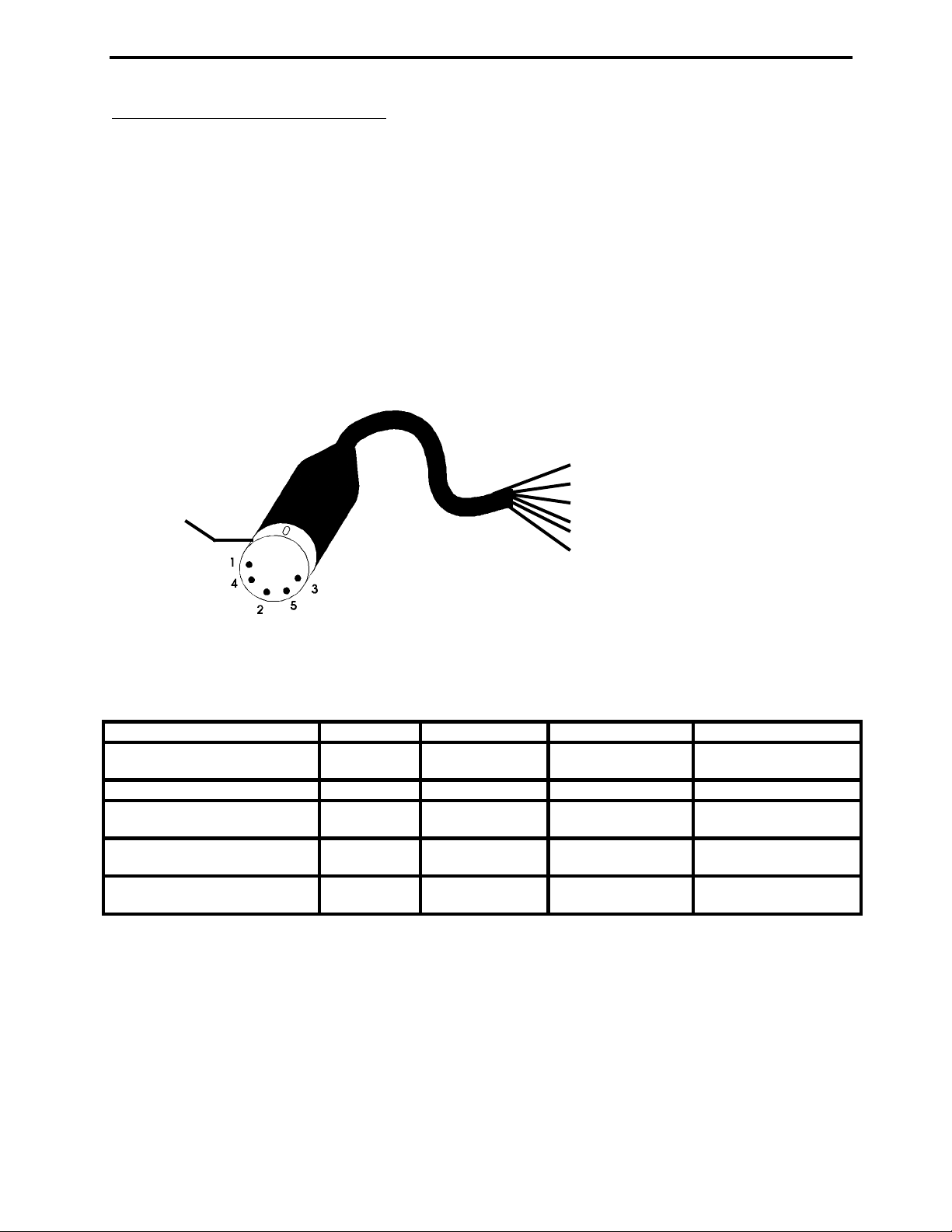
The pin assignments and wire colors for the 5-pin DIN cable
which is provided are shown below:
Mic. Audio (Black)
1.
Ground (Green)
2.
PTT (Red)
3.
Rec. Audio (Yellow)
Cable Shell
4.
Squelch Input (White)
5.
Cable Shell (Bare Wire)
6.
Fig. A-1 5 Pin Din Wire Colors
MFJ offers pre-wired cables for most radios. A list of these
cables are shown below:
RADIO TYPES MFJ PK-232 TM PK-88 TM KAM TM
ICOM* MFJ-5024 MFJ-5024X MFJ-5024Z MFJ-5024YV
YAESU HTs
KENWOOD HTs** MFJ-5026 MFJ-5026X MFJ-5026Z MFJ-5026YV
YAESU MFJ-5080 MFJ-5080X MFJ-5080Z MFJ-5080YV
8 PIN RADIOS MFJ-5080YH
ICOM*** MFJ-5084 MFJ-5084X MFJ-5084Z MFJ-5084YV
8 PIN RADIOS MFJ-5084YH
KENWOOD/ALINCO MFJ-5086 MFJ-5086X MFJ-5086Z MFJ-5086YV
8 PIN RADIOS MFJ-5086YH
Table A-2 Radio Cables
*Does not include IC-W2A
**Does not include 2500
***Does not include 25A & 255A
NOTE: The YV models connect to the VHF port of KAM. The YH
models connect to the HF port of KAM.
A-2
Page 27

MFJ-1214PC Multimode
APPENDIX
DECIMAL TO HEXADECIMAL CONVERSION
Dec Hex Dec Hex Dec Hex Dec Hex Dec Hex Dec Hex Dec Hex Dec Hex
0 0 32 20 64 40 97 61 129 81 161 A1 193 C1 225 E1
1 1 33 21 65 41 98 62 130 82 162 A2 194 C2 226 E2
2 2 34 22 66 42 99 63 131 83 163 A3 195 C3 227 E3
3 3 35 23 67 43 100 64 132 84 164 A4 196 C4 228 E4
4 4 36 24 68 44 101 65 133 85 165 A5 197 C5 229 E5
5 5 37 25 70 46 102 66 134 86 166 A6 198 C6 230 E6
6 6 38 26 71 47 103 67 135 87 167 A7 199 C7 231 E7
7 7 39 27 72 48 104 68 136 88 168 A8 200 C8 232 E8
8 8 40 28 73 49 105 69 137 89 169 A9 201 C9 233 E9
9 9 41 29 74 4A 106 6A 138 8A 170 AA 202 CA 234 EA
10 A 42 2A 75 4B 107 6B 139 8B 171 AB 203 CB 235 EB
11 B 43 2B 76 4C 108 6C 140 8C 172 AC 204 CC 236 EC
12 C 44 2C 77 4D 109 6D 141 8D 173 AD 205 CD 237 ED
13 D 45 2D 78 4E 110 6E 142 8E 174 AE 206 CE 238 EE
14 E 46 2E 79 4F 111 6F 143 8F 175 AF 207 CF 239 EF
15 F 47 2F 80 50 112 70 144 90 176 B0 208 D0 239 EF
16 10 48 30 81 51 113 71 145 91 177 B1 209 D1 240 F0
17 11 49 31 82 52 114 72 146 92 178 B2 210 D2 241 F1
18 12 50 32 83 53 115 73 147 93 179 B3 211 D3 242 F2
19 13 51 33 84 54 116 74 148 94 180 B4 212 D4 243 F3
20 14 52 34 85 55 117 75 149 95 181 B5 213 D5 244 F4
21 15 53 35 86 56 118 76 150 96 182 B6 214 D6 245 F5
22 16 54 36 87 57 119 77 151 97 183 B7 215 D7 246 F6
23 17 55 37 88 58 120 78 152 98 184 B8 216 D8 247 F7
24 18 56 38 89 59 121 79 153 992 185 B9 217 D9 248 F8
25 19 57 39 90 5A 122 7A 154 9A 186 BA 218 DA 249 F9
26 1A 58 3A 91 5B 123 7B 155 9B 187 BB 219 DB 250 FA
27 1B 59 3B 92 5C 124 7C 156 9C 188 BC 220 DC 251 FB
28 1C 60 3C 93 5D 125 7D 157 9D 189 BD 221 DD 252 FC
29 1D 61 3D 94 5E 126 7E 158 9E 190 BE 222 DE 253 FD
30 1E 62 3E 95 5F 127 7F 159 9F 191 BF 223 DF 254 FE
31 1F 63 3F 96 60 128 80 160 A0 192 C0 224 E0 255 FF
Table A-3 Decimal to Hexadecimal Conversion Table
A-3
Page 28

MFJ-1214PC Multimode
APPENDIX
TROUBLESHOOTING GUIDE
Q: My printer will not print my pictures. What do I do?
A: Choose another printer driver. See PRINTER
CONFIGURATION in the configuration section. If this does not
fix it, check the printer(LPT) port set in configuration. Try
to print using the other two possible values. The three
choices are LPT1, LPT2, or LPT3.
Q: When I try to view my pictures, they do not show up
correctly on my screen. How can I fix it so I can see my
pictures?
A: Reconfigure your video by running setmode or by the F1
Configuration option at the main menu. See SETMODE in the
configuration section.
Q: The cable from the MFJ-1214PC to my computer won't fit
to the serial port at the back of my computer. What should I
do?
A: You need to get a 25-pin to 9-pin serial port converter.
Or if you prefer, send the serial cable back to MFJ for a 25pin to 9-pin serial cable at no cost.
Q: I can't get the cross-hair on the "TAB VIEW FAX" screen
to move. How can I fix this?
A: Try pressing "NUM LOCK" and using the arrow keys on the
number keypad.
Q: Everything seems to be OK when I press T for the Test
Patterns in the System Setup, but NOTHING AT ALL--not even
trash on the screen--is coming through to my computer when I
try to Receive a FAX.
A: 1) Follow the Step-by-Step Instructions on how to receive a
FAX.
2) Check the power to the MFJ-1214PC and to your
radio, cable connections from the computer to the MFJ1214PC and from the MFJ-1214PC to the radio.
3) Try a different COM Port and Interrupt at the System
Setup.
Technical Assistance:
If you have any problem with this unit first check the
appropriate section of this manual. If the manual does not
reference your problem or your problem is not solved by reading
the manual, you may call MFJ Technical Service at 601-323-0549 or
the MFJ Factory at 601-323-5869. You will be best helped if you
have your unit, manual and all information on your station handy
so you can answer any questions the technicians may ask.
You can also send questions by mail to MFJ Enterprises, INC., 300
Industrial Park Road, Starkville, MS 39759; by FAX to 601-323-
6551; through Compuserve at 76206,1763; or by email to
76206.1763@Compuserve.com. Send a complete description of your
A-4
Page 29

MFJ-1214PC Multimode
APPENDIX
problem, an explanation of exactly how you are using your unit,
and a complete description of your station.
A-5
Page 30

MFJ-1214PC Multimode
APPENDIX
MFJ Order Form for MFJ-1214PC Accessories
T I need to order another size floppy disc with the NEW version
of the 1214 Software
I have a T 5.25" Floppy Drive T 3.5" Floppy Drive
I need T 360 KByte disks T 720 KByte Disks T
HighDensity Disks
T I have a hardware incompatibility and need the OLD version of
the 1214 Software
I have a T 5.25" Floppy Drive T 3.5" Floppy Drive
I need T 360 KByte disks T 720 KByte Disks
To exchange disks send the disk you have plus $5.00 for shipping
and handling with this form to MFJ. Copies of this form will not
be accepted for disk exchanges.
T I need a 9 Pin to 25 Pin Cable. I am returning mine for
replacement.
T I need an open end cable for my radio.
T MFJ-5082
T MFJ-5224
T MFJ-5226
T MFJ-5268
T I need a prewired cable Model________________ see Table A-2.
T I would like a MFJ-1272B/1272M Mike Switch. see pages 1-6
Name __________________________________________ MS Residents Add 7% ______
Address ________________________________________ Shipping 1 pc.
City & State__________________________Zip_________ Shipping 2 pc. Add
Telephone No.________________________ Shipping Disk
Method of Payment
Open end cable with 8-pin microphone plug
Open end cables for ICOM/YAESU handhelds
Open end cable for KENWOOD handhelds
Open end cable with Modular telephone plug
TOTAL ______
$9.95
$9.95
$9.95
$9.95
$14.95
$39.95
$6.00
$2.00
$5.00
T Check T Money Order T Master Card T American Express T
Discover T VISA
Card Number ________________________ Expiration Date ____/____
Signature of Card Holder
_____________________________________
Send this completed form, plus check or money order with proof of
purchase
(and disks or 25 pin cable) to
MFJ Enterprises, INC.
300 Industrial Park Road
Starkville, MS 39759, USA
A-6
Page 31

MFJ-1214PC Multimode
CW/RTTY/ASCII FUNCTIONS
CW/RTTY/ASCII Functions
This section will outline the different functions of the
software. These functions are in a menu on all of the
CW/RTTY/ASCII receive screens. This menu is called the
STATUS LINE.
F1 Mode
This key allows you to select between 5 different modes.
These modes appear in small sub-windows with a function key
assigned to them. So depending on the MODE you wish to
operate you press the appropriate function. For example if
you want to operate CW, then you would press the F5 key.
Pressing the F5 key will highlight the CW sub- window. After
the CW sub-window is highlighted then press the Esc key to
exit the MODE window, and enter the CW receive screen. This
procedure is the same for the other modes which appear in the
MODE window.
F2 Edit
This is another great feature of the MFJ-1214PC software.
This is a full featured editor which allows you to transmit
text files of disk or form files as you are receiving in the
CW/RTTY/ASCII modes. It is a utilizes a split screen feature
which allows you to receive in the CW/RTTY/ASCII modes at the
same time you are using the editor. For more information on
the Editor please see the Editor section.
F3 Clr
This function allows you to Clear the software Receive
Buffer. When invoked the software will prompt you with a
small window in the center of the screen.
If wish to delete the buffer contents then press the Enter
key to ACCEPT, then the Receive portion of the screen will
clear. If not then press the Esc key to CANCEL, then the
window will disappear and the Receive screen will remain
unchanged. This function also works in all CW/RTTY/ASCII
modes.
F4 Baud
The F4 key allows the user to change the transmit speed in
all CW/RTTY/ASCII modes. The graduations are in Baud Rate.
8-1
Page 32

MFJ-1214PC Multimode
CW/RTTY/ASCII FUNCTIONS
Since the RTTY/ASCII modes use Baud Rate for speed then just
set the baud rate to the appropriate speed desired. However,
CW uses Words-per-Minute (wpm). The F4 key function is
graduated in Words-per-Minute (WPM) in the CW mode. The Baud
Rate or WPM can be changed with either the arrow keys or with
a mouse. To change with a mouse, you click on the Baud
Rate/WPM slider bar, hold down the left button and slide the
bar up or down. As the slider bar is moved the Baud Rate or
WPM will change. The SELECT BAUDRATE window will appear as
shown below:
PLACE BAUD RATE SELECT TABLE HERE
Fig. 8-1 Baud Rate Select Menu
This window will change to WPM in the CW mode. The WPM will
appear as shown below:
Select WPM
8-2
Page 33

MFJ-1214PC Multimode
CW/RTTY/ASCII FUNCTIONS
Fig. 8.2 Select WPM Menu
The numbers inside the small boxes correspond to the baud
rates or WPM designated in the boxes. These baud rates and
WPM are fixed and cannot be changed. To select one just
press the corresponding number. The baud rate value will
appear next to CR ACCEPT. This value is not adopted by the
program until you press the Enter. Then you will notice the
screen change to the CW Receive screen and the WPM value you
selected will appear next F4 on the STATUS LINE.
If you desire a different baud rate then return back to the
SELECT WPM screen by pressing the F4 key. You can change the
baud rate to other values besides the fixed values. This is
done by using the Up and Down arrow keys and the PgUp and
PgDn keys. T he baud rate is changed by 1 baud increments
using the Up and Down arrow keys, and by 50 baud increments
using the PgUp and PgDn keys. The baud rate can be varied
from 30 to 1200 baud. The same procedure applies here as in
the fixed values. If you want to use the value you selected
then press the Enter, the SELECT BAUDRATE will disappear and
the CW Receive screen will appear. The program will adopt
the selected baud rate by placing it on the STATUS LINE next
to F4. If not press the Esc key and the baud rate will
remain unchanged. This is also functional in the RTTY/ASCII
modes. The way this function works in the RTTY/ASCII modes is
exactly the same as in CW.
F5 Normal/Reverse
This function has the ability to invert the polarity of the
Demodulated signal which goes to the computer. This must be
set to NORMAL for CW operation, both receiving and
transmitting. This is also functional in the RTTY/ASCII
modes. So if in the RTTY mode and good copy is not received
then try changing this function, to either NORMAL or REVERSE
which ever is the opposite of the current operating setting.
If good copy is still not obtained then set it back like it
was.
F6 LE/FI
This function is only for the RTTY/ASCII modes. This
strictly an indicator of which type of characters are being
received. This is going to have either LE for LETTERS or FI
for FIGURES (NUMBERS). This indicator will vary with what is
being received. This has no effect on CW copy or
transmitting.
F7 Save
8-3
Page 34

MFJ-1214PC Multimode
CW/RTTY/ASCII FUNCTIONS
This is a feature where the contents of the Receive Buffer is
saved to disk under a specified filename. This function is
good for all CW/RTTY/ASCII modes of operation. Upon invoking
the F7 key you will notice a small window appear in the
center of the screen like the one below:
PUT SAVE OPTIONS SCREEN HERE
Fig.. 8-3 Save Options Menu
Now let's get into the different functions under this window.
F1 Save Buffer Only
This function saves what is currently in the Receive buffer.
To do this press the F1 key and the SAVE BUFFER CONTENTS menu
will appear. From here is where all buffer save routines
start. Once you are in the SAVE BUFFER CONTENTS menu press
the TAB key to put the cursor into the DRIVE/PATH/FILENAME
options box. From here you can either delete the current
filename with the BACKSPACE key and type in another filename
and press the Enter, or just press the Enter key to use the
current filename. Once Enter is pressed the text will be
saved to disk under the specified filename.
F2 Save Buffer
Pressing the F2 key under the SAVE OPTIONS window will take
you to the SAVE BUFFER CONTENTS menu. Once there use the TAB
key to put the cursor into the DRIVE/PATH/FILENAME box. Here
you can either use the current filename by pressing the Enter
key or use the BACKSPACE key to delete the current filename
and type in your own, and press the Enter key. Once the
Enter key is pressed the program will open a file on the
default disk drive, using the specified filename. After the
8-4
Page 35

MFJ-1214PC Multimode
CW/RTTY/ASCII FUNCTIONS
file is opened on disk the program return to the Receive
screen, highlight F7 SAVE on the STATUS LINE. At that time
all incoming text received by the program will be written to
that file. When you wish to close the file just press the F7
key again. The F7 SAVE will no longer be highlighted on the
STATUS LINE. From there you can use the editor to go back
and look at the file.
F3 Save Current
Pressing the F3 while under the SAVE OPTIONS window will take you
to the AUTOSAVE BUFFER menu. Once in the menu you need to select
a filename which to SAVE the incoming data to. To do this you
can use the TAB key to put the cursor in the DRIVE\PATH\ FILENAME
box on the right side of the menu. Then you can either use the
current selection which may be in the box already, or you can use
the Del key to delete the current selection. After deleting the
DRIVE\PATH\FILENAME currently in the box, type in your own choice
and press the ENTER key. The program will then return to the
terminal screen and the F7 SAVE selection on the status line will
be highlighted. After everything is setup properly, then all
incoming data will be saved to disk, via the DRIVE\PATH\FILENAME
which you specified.
When you wish to terminate the AUTOSAVE routine, then just press
the F7
key again.
F8 Print
The PRINT function allows printing of CW/RTTY/ASCII text out
on the printer. The printer must be connected to the
computer at the parallel port, and must be ON-LINE. If the
printer is not ON-LINE or connected, the computer will not
lock-up. Then all you have to do is bring the printer ON-LINE
and or connect it to the computer, then proceed with your
printing operation. If it seems like the printer is not
working quite right, then you may need to change the printer
driver the program is using. The default printer driver is
named STANDARD.FPR. In order to printer drivers rename the
STANDARD.FPR file something else, then rename the printer
driver file that matches the specifications of your printer
STANDARD.FPR. The ten (10) printer driver files available
are:
EPSON__8.FPR LJ_75.FPR
STANDARD.FPR (DEFAULT) LJ_150.FPR
EPSON_24.FPR P7_COL_8.FPR
LJ_300.FPR P7_COL24.FPR
LJ_100.FPR EPSWX_24.FPR
8-5
Page 36

MFJ-1214PC Multimode
CW/RTTY/ASCII FUNCTIONS
F9 Adjust
This is a very unique feature which gives the you an ONSCREEN Tuning Indicator for the RTTY/ASCII modes. When the
F9 key is invoked the Tuning Indicator will appear in the
center of your screen. It is a 16 increment "BAR GRAPH"
indicator and is very useful in signal tuning. Below is an
example of the ON-SCREEN tuning indicator:
PLACE THE TUNING INDICATOR EXAMPLE HERE
Fig. 8-4 Tuning Indicator
F10 Analyzer
This feature gives you the ability to ANALYZE the baudrate of
the incoming RTTY or ASCII signal.
P TX Params
When the P key is pressed from any of the receive screens a
small menu will appear in the center of the screen. The menu
will appear as follows:
8-6
Page 37

MFJ-1214PC Multimode
CW/RTTY/ASCII FUNCTIONS
PLACE THE TX PARAMS MENU HERE
Fig. 8-5 Transmit Parameters Menu
While at the TX Params menu you will see two vertical bars on
the right hand side of the menu. Below these bars you notice
that one is labeled MARK and the other is labeled SPACE.
Either the word MARK or SPACE below the bars will be
highlighted. So whichever one is highlighted can be changed
if desired. To highlight the word of the frequency to be
changed use the LEFT or the RIGHT arrow keys. Whichever one
is highlighted can be varied, by using the Up or Down arrows,
PgUp, or the PgDn keys. The Up and Down arrow keys will vary
the frequency by 1 Hz increments at a time, or you can hold
them down and the frequency will constantly change until you
release the key. The PgUp or PgDn key vary the frequency in
the same manner only in 50 Hz increments. The screen may
flicker slightly while changing the frequencies. This is
normal, there is no malfunction.
An explanation of the menu functions follows.
F1 Speaker
Pressing the F1 key along with a Enter press from this menu
will either activate or deactivate the speaker in the
computer. Pressing the F1 key at this menu you will notice
the F1 SPEAKER sub-window become highlighted. At this point
you need to press the Enter to accept the change. If you do
not want to activate the internal speaker then press the Esc
key to abort the change. Once activated all received signals
will be heard on the computer's internal speaker
F2 Qrm Mode
This function changes the way an RTTY/ASCII signal is
transmitted. It changes the time duration between
characters. This is useful when operating in high QRM
conditions. In order to enter the QRM MODE press the F2 key
from the TX Params menu. You will notice the F2 QRM MODE
sub-window become highlighted. For this change to take place
you must press the Enter key. If not, then press the Esc key
and the change will not be made.
F3 Synchronous Mode
This mode when activated transmits the RTTY DIDDLE signal,
when transmitting RTTY. In order to enter this mode press the
F2 key from the TX Params menu. You will notice the F2
SYNCHRONOUS MODE sub-window become highlighted. For any
change to take place you must press the Enter key. If not,
then press the Esc key and the change will not be made.
CR Accept
8-7
Page 38

MFJ-1214PC Multimode
CW/RTTY/ASCII FUNCTIONS
Pressing the Enter or ENTER key tells the software to adopt
the changes you made while at the TX Params menu.
Esc Cancel
Pressing the Esc tells the software not to make any changes
you made while you were in the TX Params menu.
Mark 2125 Hz.
This is the MARK frequency used by the MFJ-1214PC to transmit
RTTY or ASCII. This frequency is variable which will be
explained later on. This frequency is variable from 379 to
3000 Hz.
Space 2295 Hz.
This is the SPACE frequency used by the MFJ-1214PC to
transmit RTTY or ASCII. This frequency is variable which
will be explained later on. This frequency like the MARK
frequency can be varied from 379 to 3000 Hz.
R- RX Params
When the R key is pressed from any of the receive screens a
small menu will appear in the center of the screen. The menu
will appear as follows:
PLACE THE RX PARAMS MENU HERE
Fig. 8-6 Receive Parameters Menu
Under this menu you will see three (3) choices . Let explain
these choices now so you will better understand them.
8-8
Page 39

MFJ-1214PC Multimode
CW/RTTY/ASCII FUNCTIONS
F1 Mark and Space
Pressing the F1 key while at the RX Params menu will set up
the software to copy RTTY/ASCII signals, using both component
frequencies, MARK and SPACE. This is known as the ANALOG
mode, which we explained earlier in the RTTY/ASCII receive
section of this manual. This is only to be used with RTTY or
ASCII modes of operation, not in CW. Once pressed the F1 MARK
and SPACE sub-window will become highlighted. Once you have
made your selection, press the Esc to exit the RX Params
menu.
F2 Space Only
Pressing the F2 key will highlight the F2 SPACE ONLY subwindow within the RX Params menu. This function will set the
software into the DIGITAL mode for copying RTTY or ASCII
signals, using only the SPACE frequency. This sometimes is an
easier way to copy RTTY. This is what needs to be selected
when copying CW. Once you have made your selection press the
Esc key to exit the RX Params menu.
Exit
Pressing the Esc key will exit the RX Params menu. When the
menu is exited any changes made while in the menu will be
adopted by the software.
Mode Configurations
Here is a very nice feature where you can configure the MFJ1214PC just about any way you choose. You can have as many
configurations as you want. You can designate them with
filenames of your choice. You can make up files using
different combinations of either baudrate, RTTY shifts, CW
speeds, etc. The files are made up with information from
other software functions. These functions are as follows:
F1 MODE
RX PARAMS
TX PARAMS
F4 SELECT BAUDRATE
F5 NORMAL/REVERSE
There are several configuration files already on disk with
pre-determined parameters. Let us get into how SAVE and LOAD
configuration files.
Load Conf
8-9
Page 40

MFJ-1214PC Multimode
CW/RTTY/ASCII FUNCTIONS
This function will you to load configuration files in order
to configure the MFJ-1214PC any way you desire. When the L
key is pressed from any of the receive screens, another
screen will appear.
From this screen you can load any of the configuration files
on disk. In the upper left corner there will be a list of
files with RII extensions. These are the configuration
files. If you wish to use one of them, then press the Up or
Down arrow keys to select the appropriate file. When the
proper file is highlighted then press the Enter key twice.
At that time the program will load the selected
configuration. If you do not find the configuration desired
then you can make your own. See the section on Save Conf.
Save Conf
This feature will allow you to save your configuration files
which you make up. Once you have your configuration setup,
return to the receive screen. At the receive screen press
the S key to save the configuration you just made. When the
S key is pressed from any of the receive screens, the SAVE
CONFIGURATION screen will appear. You will notice a list of
files with RII extensions in the upper left corner. These
are the configuration files. It is advisable that you do not
write over the sample configuration files. You can enter a
new filename by pressing the TAB key. When TAB is pressed
you will see the cursor appear in the DRIVE/PATH/FILENAME box
in the lower right portion of the screen. Enter the filename
of your choice along with the extension desired, from the
point where the cursor is, and press the Enter key once.
When the Enter key is pressed the file is saved to disk under
the specified name. The receive screen previously in use
will appear.
There are a couple of functions within the Configuration
screen which we need to discuss.
TAB
Pressing the TAB key while at the Configuration screen will
move the cursor to the DRIVE/PATH/FILENAME box in the lower
left portion of the screen. This is where you can specify
the DRIVE/PATH/FILENAME to which you want to either Load or
Save a configuration file. So if you wanted to load a
configuration file from Drive C, inside directory named
HAM\RTTY, and the filename was 50RTTY.prm, follow the steps
below:
1. Using the BACKSPACE key delete the exiting statement in
the DRIVE\PATH\FILENAME box.
2. Type in the statement below and press the Enter key:
C:\HAM\RTTY\50RTTY.PRM
8-10
Page 41

MFJ-1214PC Multimode
CW/RTTY/ASCII FUNCTIONS
NOTE: The file will not appear in the upper left corner until
you tell the software what file extension to look for. So
from here let us go to the next function.
INS
This function is where you designate alternate file
extensions. Pressing the INS or INSERT key on your will move
the cursor to the FILE EXTENSION box, which is just above the
DRIVE\PATH\FILENAME box. You will also notice the letters
INS in the lower right corner of the box. In order to enter
your file extension please follow the steps that follow
1. Use the BACKSPACE key to delete the default file
extension.
2. Now using the example in the explanation on the TAB
function here is what you would type in the FILE
EXTENSION box:
.PRM
(Make sure that there is a period in front of the PRM.)
After entering the file extension for the software to look
for, press the Enter key. The file extension is always
defaulted to RII, regardless of what you change it to at the
configuration screen. When the Enter key is pressed your
filename 50RTTY.PRM will appear in the upper left corner of
the configuration screen. In order to LOAD the 50RTTY.PRM,
just use the Up or Down arrow keys to select the 50RTTY.PRM
file and press the Enter key twice. The software will load
your configuration file and return to the receive screen.
Now you are ready to operate RTTY at 50 baud. As you just
seen with the previous example, it is very easy to configure
the MFJ-1214PC.
Up & Down Arrows
The Up and Down arrow keys allow you to scroll backward or
forward through either the receive text buffer or the text
Editor. Scrolling is done 1 line at a time.
PgUp or PgDn
The PgUp and PgDn keys allows you to scroll backward or
forward through the receive text buffer or the text Editor.
Scrolling is done 1 page at a time.
Home
The HOME key allows you to return back to the very beginning
of either the receive text buffer or text Editor. It does
8-11
Page 42

MFJ-1214PC Multimode
CW/RTTY/ASCII FUNCTIONS
not matter where you are in the receive text buffer or text
Editor.
End
The END key will allow you to jump ahead to the very end of
the receive text buffer or text Editor. Here again it does
not matter where you are, pressing the END key will take you
all the way to the end of the buffer or Editor.
T Timer
Here is a very nice feature which you can use to setup "Timed
Reception" of CW/RTTY/ASCII signals. Pressing the T key from
any of the receive screens will take you to the START/STOP
TIMER menu.
At the top of the menu you will see three (3) function keys
with particular functions next to them. Also below the F1
and F2 functions you notice small windows with two pair of
zeros separated by a colons. The window below the F1
function is highlighted. An explanation of each function
follows.
F1 Start
This is where you will set the START time in order to tell
the software to start reception. Press the F1 key with the
RIGHT arrow key. When the RIGHT arrow key is pressed the HH
in the lower right corner of the menu will highlight. All
you have to do now is to press the Up arrow key to set the
HOUR according to what you see in the F1 STRT window. The
HOUR is variable from 00:00 to 23:00. Now to set the MINUTE
at which to START reception. First press the right arrow key
to highlight the MM in the lower right corner of the menu.
All you have left to do is press the Up or Down arrow keys
and set the actual minute. Let's go on to setting the STOP
time.
F2 Stop
This is where you will set the STOP time to tell the software
to stop reception. So to set the stop time let us start by
pressing the F2 key. You will notice the small window below
F2 STOP will become highlighted. Press the left arrow key to
highlight the HH in the lower right corner of the menu. Now
8-12
Page 43

MFJ-1214PC Multimode
CW/RTTY/ASCII FUNCTIONS
use the Up and Down keys to set the HOUR which you want to
stop reception. The HOUR is set between 00:00 to 23:00.
Just as in setting the START time, you need to press the
right arrow key to highlight the MM in the lower right corner
of the menu. All that is left to be done is use the Up or
Down arrow keys to set the MINUTE.
Once you have set your START and STOP times, you will need to
press the Esc key. This will exit the TIMER menu.
8-13
Page 44

MFJ-1214PC Multimode
CW Operation
CW Operation
In this section we will explain the CW options and operation. We
will show you how to receive and transmit CW, and just basically
how to use the software to obtain good overall results in
operating CW.
One of the simplest and easiest ways to send information is by
continuous-wave or CW. Each letter is identified by a particular
sound. This sound is made up of several short and long sounds,
which relate to DOTS and DASHES respectively. For instance the
letter E is a short sound, a dot, and the letter T is a long
sound, a dash. There is also a part of CW which is referred to
as a BREAK. There are short breaks between letters and long
breaks between words. So as you see there are three (3) different
parts of a CW transmission, the SHORT sound, the LONG sound and
the BREAK.
Standards for CW Transmission and Reception
The MFJ-1214PC operates both modulated and true CW. Modulated CW
is where you key the radio by grounding the PTT input at the
Microphone jack, then send audio into the microphone at the
Transmit audio pin.
True CW is where you key the radio through the KEY jack on the
back of the radio. The MFJ-1214PC comes from the factory ready
to operate FAX, RTTY, and CW.
Even though this CW program is capable of running RTTY, ASCII,
and BAUDOT, you will get better performance from using the RTTY
program.
CW Tuning Procedure
In this procedure we will take you through the technique of how
to tune in a CW signal and obtain good copy of all CW signals.
1. Position the FAX-RTTY/CW switch in the RTTY/CW position which
is with the push-button out. Connect your radio to the MFJ1214PC. Position the BANDWIDTH control so the pointer is in
the straight up position.
2. Load the VT program.
3. Press the F3 key ( Send/Receive RTTY ), at this time you will
see the screen change to RTTY receive. This is normal.
4. Once you have the RTTY receive screen you will notice more
choices at the bottom the screen. Look in the second block
from the left on the STATUS LINE and you will notice a
7-1
Page 45

MFJ-1214PC Multimode
CW Operation
function referring to F1 MODE. This is the next key press,
so let's press the F1 key.
5. After pressing the F1 key you will notice a larger window
like the one shown below appear in the center of the screen:
Place window here
Fig. 7-1 Mode Select Menu
6. Press the F5 key. You will notice that the CW subwindow
become highlighted.
7. Once the CW subwindow is highlighted press the Esc key to go
to the CW Receive mode.
8. When the CW receive screen is present you will need to setup
the RX Params. This is done by pressing the R key while at
the CW receive screen. When the R key is pressed you will
notice another window appear in the center of the screen,
like the example below:
PLACE RECEIVE PARAMETERS SCREEN
HERE
7-2
Page 46

MFJ-1214PC Multimode
CW Operation
Fig. 7-2 Receive Parameters Menu
9. You will need to press the F2 key for SPACE ONLY. This is
required for proper CW mode operation. After pressing F2,
press the Esc key to return to the CW Receive screen.
10. Once back you are back at the CW receive screen you will
need to check to see if the internal speaker is active. This
is done by pressing the P key. When the P key is pressed the
screen will change to the Transmit Parameters screen, which
appears below:
TRANSMIT PARAMETERS screen here
Fig. 7-3 Transmit Parameters Menu
Once the Transmit Parameters screen is obtained in the manner
described above then press the F1 key. After pressing the F1 key
the box designated F1 SPEAKER will be highlighted. This means
that if your computer has an internal speaker installed that it
is now active. Active meaning that when a CW signal is tuned in
properly the signal will be heard in the computer speaker and in
the radio speaker at the same time. When you have pressed the F1
key and highlighted the F1 box, then exit the Transmit Parameters
window with the Enter key.
At this point you should be back at the CW Receive screen, ready
to receive some CW. Now in order to tune in a CW signal you must
first set your radio to the CW mode. Then rotate your VFO knob
on your radio until you find a CW signal. When the CW signal is
found you must tune the radio starting on the HIGH side of the
signal (HIGH PITCH), down toward the LOW side of the signal (LOW
PITCH). This must a done very slowly, due the fact that the
filtering in the MFJ-1214PC is very sharp. The center frequency
of the filter in the MFJ-1214PC is 800 Hz.
7-3
Page 47

MFJ-1214PC Multimode
CW Operation
Now as you are tuning, listen for the CW signal in the speaker in
your computer. When the signal is heard it should be clean with
very little distortion, if not FINE tune your VFO until the
signal heard is as clean as possible. If everything was done
properly you should be getting good CW copy on your computer
screen.
NOTE: If your radio has any filtering such as a NOTCH filter
this could help eliminate background static and noise.
If you have any problems obtaining good copy then go back through
the tuning procedure. If you still don't obtain copy the problem
could related to any one of the following:
Computer Cable
The computer cable could be at fault here. The cable could be
mis-wired or have bad continuity through the length of the cable.
Also the cable may be connected to the wrong COMport. Try
changing the cable or checking for continuity and shorts between
the pins. Also check the physical connection to the COMport.
Ensure that the COMport designated in the SETUP and the COMport
you have the cable connected to is the same.
Serial Card
The serial card maybe bad or configured for the wrong COMport.
Check your computer manual or the instruction sheets which came
with the serial card for the proper COMport configuration.
Power Input
If the MFJ-1214PC does not have 12 VDC applied or if the supply
has dropped then the internal voltage regulator will fail. This
will cause the MFJ-1214PC not to copy CW.
If any problems are encountered in trying to receive CW and you
have tried the three (3) items above then please feel free to
contact our Technical Staff at 1-800-647-8324. They will be more
than happy to help.
CW Transmission
Now we are going to get into transmitting CW with the MFJ-1214PC.
First you must setup the MFJ-1214PC and the software as mentioned
in the CW Tuning procedure, in order to operate CW.
Once you have the MFJ-1214PC connected to the radio and the
computer then you are ready to transmit CW.
In order to transmit CW you must go to the Editor. This is done
by first going to the CW Receive screen as described in the CW
Tuning procedure. Then if you look at the bottom of the screen
you will see all of the functions available to you in the CW
mode. One of these is F2 EDIT. If you press F2 the CW Receive
7-4
Page 48

MFJ-1214PC Multimode
CW Operation
screen will split into two (2) parts. The upper portion is the
receive screen and the bottom portion is the Editor. From here
you can be receiving CW in the upper screen and be forming a
message in the Editor in the bottom screen. You can also load
the Editor with a text file from disk, edit it for transmission,
then transmit it when ready. The way in which you actually
transmit CW is by using the F1 and F2 keys in the Editor. Let's
go into the actual functions of the F1 and F2 keys in the Editor.
F1 Tx All
This function will allow you to transmit the entire Editor
content. When F1 is pressed the MFJ-1214PC will key the
radio, then start transmitting the Editor contents. When
finished you must press the F1 key again in order to unkey
the radio.
F2 Tx Cur
This keystroke will key the radio and allow you to type your
message. The message will be sent as you type it into the
Editor. Here again when you are finished you must press the
F2 key to unkey the radio and stop sending.
If you have any problems or difficulties operating this
section of the software please go back and re-check the
following things:
Radio Cable
Ensure that the cable connected between your radio and the MFJ1214PC. Check it for continuity and that all connections are
secure and soldered well.
Radio Setup
Make sure the radio is setup properly for CW operation. If the
radio is not setup right your operating will suffer.
System Setup
Ensure that the MFJ-1214PC is setup properly. Also make sure the
software is setup right. Go and re-check setup according to the
CW Tuning procedure.
If you check all items above please feel free to contact our
Technical Staff at 1-800-647-8324. They will be more than happy
to help you in any way they can.
7-5
Page 49

MFJ-1214PC Multimode
RTTY
RTTY/ASCII Operation
In this section we will go over the operation and functions of
the RTTY/ASCII modes. Here will go into the different ways of
tuning in an RTTY/ASCII signal for good copy. Also we will talk
about transmitting RTTY/ASCII signals in relation to the
different frequency shifts, speeds, whether the signal needs to
inverted while transmitting, etc. We will also explore the
different software functions in the RTTY/ASCII modes and what
they will do for you during RTTY/ASCII operations.
System Set-Up for RTTY
The only system setup required for RTTY operation is the
selection of the serial COM port and the parallel LPT port.
Ensure that the radio is all cabled up properly for full RTTY and
ASCII operations, both receive and transmit. For more
information on system setup for the MFJ-1214PC please refer to
"F1- System Setup".
Standards for RTTY Transmission and Reception
Radio TeleTYpe is a fast and convenient way to send text. It is
used by the Military, the commercial industry, as well as the
Amateur Radio Operator.
Information is sent via a combination of two different
frequencies: Mark and Space. There are also two (2) other parts
of the RTTY signal called START and STOP pulses. Each character
or number is made up of a different combination of Marks and
Spaces. The START and STOP pulses are always at the beginning
and the end of each character or number.
First there is the Baudot RTTY mode, in which the characters and
numbers are made up of 5 bits. Below is the letter D as would be
seen on an oscilloscope as a Baudot RTTY signal.
Mark
One RTTY Character
Space
Data Pulses for "D"
Start Pulse Stop Pulse
6-1
Page 50

MFJ-1214PC Multimode
RTTY
Fig. 6-1 RTTY Character "D"
Secondly there is the ASCII mode the characters and numbers are
made up of either 7 or 8 bits. Since the Baudot RTTY mode uses
less bits, there is less chance of error due to bad reception.
However, the 7 and 8 bit ASCII modes allow for upper and lower
case letters as well as special characters. The ASCII mode can be
run in a SYNCHRONOUS or an ASYNCHRONOUS mode. Below is an example
of a synchronous and an asynchronous ASCII signal as it would be
seen on an oscilloscope of the letter S:
Mark
Space
One Synchronous
Character
7 ASCII Data Bits
Mark
Space
One Asynchronous
Character
pp
7 ASCII Data Bits
Parity Bit
Fig. 6-2 Sychronous and Asynchronous ASCII Character "S"
Now that you understand a little more about RTTY, let's look at
how to receive RTTY and ASCII signals.
Start Pulse Stop Pulse
RTTY/ASCII Receive
The MFJ-1214PC supports two modes of reception, analog and
digital, and are very different in the way they operate. The
analog mode copies the signal by using the MARK and SPACE
frequencies. The digital mode copies the signal using only the
SPACE frequency only. An on-screen Tuning Indicator has been
provided for ease of use. This indicator is a 16 increment "Bar
Graph" and can accessed by pressing the F9 function key. When F9
is pressed you will see the tuning indicator displayed in the
center of your screen. This indicator should be used to tune in
signals until you get accustomed to the tuning procedure. During
the reception of any RTTY/ASCII signals the radio and MFJ-1214PC
must be set-up properly, if not your RTTY operations will be
hampered. So without any further delay let us go into the
different modes of receiving RTTY signals.
In order to copy RTTY you must first follow the procedure below
to be successful:
1. Load the VT program.
6-2
Page 51

MFJ-1214PC Multimode
RTTY
2. When VT is loaded you will see the nine (9) small sub-windows
on the screen.
3. With the VT screen on your computer monitor, press the F3
function key, to receive RTTY. Upon pressing the F3 function
key you will notice the screen change to the RTTY Receive
screen. The program will default to the Baudot RTTY mode at
45 Baud and Normal demodulation polarity for receiving.:
4. Turn the BANDWIDTH control all the way to the clockwise
position. Position the FAX-RTTY/CW switch to the OUT
position. Also push the POWER switch to the IN position.
5. Set your radio or receiver to USB (Upper Side Band) and the
volume to a comfortable listening level.
This concludes the initial set-up of the program and the MFJ1214PC, and the radio. So why don't we get into receiving an
actual RTTY signal, starting with the ANALOG mode. There is no
need to set the program into the ANALOG mode because the software
already comes set up in the ANALOG mode of operation. So all you
have to do is tune the radio to an RTTY signal, preferably a
signal in the Amateur bands for initial testing.
Once you have a signal tuned in on the receiver press the F9
function key. At this time you should see the Tuning Indicator in
Figure 6-3.
Once the indicator is on-screen, tune the VFO on your radio
starting from the low-side of the signal. While you are tuning
the VFO from the low-side toward the high-side of signal watch
the Tuning Indicator. Tune it very slowly until you can have
both of the end BARS up, and there is a "VALLEY" between the two.
Once you have the "VALLEY" you may need to vary the VFO slightly
one way or the other to achieve good copy. This may be a little
touchy due to the sharp filtering in the MFJ-1214PC, but do not
give up. Once you achieve the optimum tuning point you should be
receiving good copy. Here is an example of the on-screen Tuning
Indicator when a RTTY signal is tuned in properly and the MFJ1214PC is copying the signal well:
PLACE THE TUNING INDICATOR EXAMPLE DURING COPYING RTTY HERE
6-3
Page 52

MFJ-1214PC Multimode
RTTY
Fig. 6-3 RTTY Tuning Indicator Receiving
If your screen does not appear as shown on page 3 please go back
and check the following items:
COMPORT
Ensure the COMport which the MFJ-1214PC is connected to is the
same one as the program is configured for including the
INTERRUPT. Remember to use Interrupt 4 for COM1 and Interrupt 3
for COM2. This can be easily checked by pressing the Esc key
then the Enter to exit back to the VT screen. Then press the F1
key to check the program setup. Please refer to the SETUP
section of the software for further information on the program
SETUP.
SERIAL CABLE
Make sure that the serial cable is in good condition. Ensure
that the cable is connected to the proper COMport which is in the
software configuration. If the cable is in doubt of being good
or bad, then replace it.
HARDWARE SETUP
Ensure the MFJ-1214PC is setup properly as stated in this
section. Make sure that is power applied, the radio is
connected, and the computer serial cable is connected to the MFJ1214PC. Also ensure that the MFJ-1214PC has it's power switch is
in the ON position.
MODE CONFIGURATION
If you are not receiving good copy the problem could be that the
software MODE CONFIGURATION may not be set properly. Refer to
the CW/RTTY/ASCII functions section of this instruction manual as
to how to setup the MODE CONFIGURATION. Make sure it is set
properly for the mode which you trying to operate.
Auto Converter
You also have the ability to compensate for incorrect radio
tuning, and what the program sees coming from the analog-digital
converter in the MFJ-1214PC. This is done via the Auto-Converter
function mentioned in the RX Params in the RTTY program. When
the Auto Converter is activated you have a few more functions
available, so let's go over them now:
6-4
Page 53

MFJ-1214PC Multimode
RTTY
F Full ADC Range
This allows you to use the entire range of the tuning indicator.
The radio tuning must be precise. Here there is no room for
error. The LO, MI, and HI frequency points do not change.
A Auto ADC Adjust
This feature takes some of the guess work out of radio tuning.
You do not need to be right on the received signal, just close.
Once you are close to the signal just press the A key. The
program will start to analyze the incoming signal, and will set
the LO, MI, and HI points on the tuning indicator. This will
assist in RTTY or ASCII reception. You can test this by tuning
to an RTTY signal so the MFJ-1214PC copies it. Then slightly
change the VFO on the radio so the MFJ-1214PC copy is bad, then
press the A key. After the program is finished the MFJ-1214PC
should again be copying the RTTY signal.
O Lo-Level
This will allow you to manually change the LO frequency point.
This can be changed with the arrow keys or a mouse. As you move
the LO point the LO indicator on the tuning indicator will move.
Mi-Level
This will allow you to manually change the MI frequency point.
This can be changed with the arrow keys or a mouse. As you move
the MI point the MI indicator on the tuning indicator will move.
Hi-Level
This will allow you to manually change the MI frequency point.
This can be changed with the arrow keys or a mouse. As you move
the HI point the HI indicator on the tuning indicator will move.
RTTY Transmit
All transmitting in the RTTY/ASCII modes is done out of the text
Editor. You can transmit text files or just "RAGCHEW" with a
friend. Before attempting to operate RTTY or ASCII please read
the TEXT EDITOR section carefully. Get to know what the Editor
commands will do. If you do not, then you could damage your
equipment, by leaving the radio in a constant keyed down state.
Below you will find a couple of the Editor functions used to
transmit RTTY. However, before using them you must first be at
the RTTY receive screen and accessed the Editor by pressing the
F2 function key.
F1 Tx All
This function will allow you to transmit what is currently in the
Text Editor. So what this means is you can already have a reply
typed into the Editor during a QSO, then when needed press the F1
key. When F1 is pressed the MFJ-1214PC will key the radio, then
start transmitting the Editor contents. When finished you must
6-5
Page 54

MFJ-1214PC Multimode
RTTY
press the F1 key again in order to unkey the radio, otherwise the
radio will stay in a keyed down state. Thus damage could result!
F2 Tx Cur
This keystroke will key the radio and allow you to type your
message. The message will be sent as you type it into the
Editor. Here again when you are finished you must press the F2
key to unkey the radio and stop sending. Otherwise, the radio
could stay in a keyed down state and damage could result!
Text Editor
Inside the MFJ-1214PC software is a very powerful TEXT EDITOR.
This Editor is used to transmit information in the CW/RTTY/ASCII
modes. You can edit text which has been received off, like a
bulletin board, then save it to disk. It incorporates a split
screen operation. This basically means you can be in a QSO with
someone, receiving and be forming a message to transmit back to
your contact at the same time. This would be great for field day
or RTTY contesting.
Below you will find the Text Editor commands and an explanation
as to their function. Please read them carefully, especially when
transmitting in the CW/RTTY/ASCII modes. It can handle files
greater than 100K.
Editor Functions & Commands
This is the section where the Editor functions and commands will
be discussed. We will take you through all functions and commands
related to the Editor, and what they will do you while operating
the different modes. The Text Editor is accessed by pressing the
F2 key from any of the receive screens. So without any further
delay lets get started.
ARROW KEYS
The arrow keys allow you to move the cursor around within the
Editor. You can scroll back or forward through text in the
Editor or in the receive screens. The Up and Down arrow keys
will scroll through text 1 line at a time. The cursor cannot be
moved around in an empty space. If you need to move the cursor
around in empty space you must use the SPACE BAR.
HOME
The Home key will take you back to the very beginning of a file
or text, within the Editor. Also you can return the beginning of
the receive screen buffer. This function applies no matter where
you are at in the Editor or receive screen buffer.
6-6
Page 55

MFJ-1214PC Multimode
RTTY
END
The End key works like the Home key, but in reverse. When
pressed it will take you all the way to the very End of the
Editor text, or receive screen buffer. It does not matter where
you are in the Editor or receive screen buffer.
PGUP OR PGDN
The PgUp and PgDn keys allow you to scroll back or forward
through text in the Editor or the receive screen buffer. It will
scroll 1 page at a time. This good if you are editing a very
large file.
ENTER
Pressing the Enter will begin a new line in the Editor. The
cursor will move down to the next line, along with any
characters.
DELETE
The Del key will erase any characters to the right of the cursor,
one character at a time. Be careful when using this because once
characters are deleted, they are non-recoverable.
BACKSPACE
The Backspace key will erase any characters to the left of the
cursor. Characters to right of the cursor are shifted to the
left one space.
F1 Tx All
Pressing the F1 key while in the Editor will cause the software
to transmit the entire contents currently in the Editor. When
pressed the F1 TX ALL on the EDITOR STATUS line will highlight.
The transmitter will key up, then very shortly after that data
will be transmitted. Once the transmission is complete then you
must press the F1 key again to unkey the transmitter.
F2 Tx Cur
Pressing the F2 key while in the Editor will cause the
transmitter to key up. When pressed the F2 TX CUR on the EDITOR
STATUS line will highlight. After the transmitter keys up then
you can start typing your message. It will be transmitted in
"REAL TIME" as you are typing it. After transmission is
completed, the F2 key must be pressed again to unkey the
transmitter.
F3 Load Text
This function is used to load the Text Editor with a text file
from disk. When F3 is pressed the LOAD EDITOR TEXT menu will
appear. This menu will appear as shown below:
6-7
Page 56

MFJ-1214PC Multimode
RTTY
PLACE LOAD EDITOR TEXT MENU HERE
Fig. 6-4 Load Editor Text Menu
The large vertical box on the left side of the LOAD EDITOR TEXT
menu is where all files and directories are displayed. Use the
Up and Down arrow keys to select the file or change to the
directory of your choice.
In the upper right corner you will see six (6) small boxes. These
will display system disk drive designators. The program will
support up to six (6) disk drives, both HARD and floppy drives.
You can change disk drives just pressing the appropriate drive
letter, without the :\. The program will automatically switch to
the selected disk drive.
Within the LOAD EDITOR TEXT menu there are a few functions which
you need to know about.
INS
The INS or INSERT key is used to change the FILE EXTENSION
designator, which the software looks for upon entering the LOAD
EDITOR TEXT menu. In order to use this function the NUM LOCK
function must be deactivated. When the INS key is pressed the
cursor is moved to the FILE EXTENSION box, and is positioned on
the last character on the current file extension designator. To
change the extension press the left arrow key once. This will
move the cursor one space to the right. Now use the BACKSPACE
key to delete to extension back to the period, then type your
extension in. Make sure the first character is a period. The
file extension should look like this: .DOC
The period must be the first character in the file extension you
use. When finished press Enter to tell the software to look for
your extension name. After the extension is entered, if there
are any files with that extension on disk, they will be displayed
on the right side of the menu.
UP AND DOWN ARROWS
The Up and Down arrow key are used to select the file or
directory to load or use. After selecting the file or directory
press the Enter key. To load the selected file press the Enter
key twice. The LOAD EDITOR TEXT menu will be exited and the
Editor will be loaded with the specified file. In order to use
the selected directory press the Enter key once. The files or
6-8
Page 57

MFJ-1214PC Multimode
RTTY
directories will be listed on the left side of the menu. Then go
through the same procedure to select the file of your choice.
BACKSPACE
The BACKSPACE key is used to list other directories on disk.
This is good for switching to another directory you wish to use.
The directories available will listed on the left side of the
LOAD EDITOR TEXT menu. Use of the Up and Down arrow keys to
select the directory you want to use, and then press the Enter
key. All files and directories within the selected directory
will be listed on the left side of the menu. Use the same
procedure to select as mentioned above to select other files or
directories.
TAB
The TAB key is used to move the cursor down to the
DRIVE\PATH\FILENAME box, in the lower right corner of the menu.
Once the cursor is in this box you can use the BACKSPACE key to
delete the current DRIVE\PATH\FILENAME and insert your own. Once
entered this DRIVE\PATH\FILENAME will be used by the software
until you exit the program.
CR ACCEPT
The Enter key is used to tell the software to load a file or use
the selected directory. When Enter is pressed the LOAD EDITOR
TEXT menu will disappear and the software will either load the
Editor, or change directories.
ESC CANCEL
The Esc key is used to tell the software to abort the Editor load
or directory change. When Esc is pressed the LOAD EDITOR TEXT
menu will disappear and everything remains unchanged.
F4 SAVE TEXT
This function is like the F3 LOAD TEXT function, but in reverse,
it saves the Editor text, instead of loading the Editor. When F4
is pressed while in the Editor the SAVE EDITOR TEXT menu will be
displayed on the screen. Here is how the SAVE EDITOR TEXT menu
will appear:
PLACE SAVE EDITOR TEXT MENU HERE
6-9
Page 58

MFJ-1214PC Multimode
RTTY
Fig. 6-5 Save Editor Text Menu
The large vertical box on the left side of the SAVE EDITOR TEXT
menu is where all files and directories are displayed. Use the Up
and Down arrow keys to select the file to which you want to save
text to or, change to the directory of your choice. In the upper
right corner you will see six (6) small boxes. These will display
system disk drive designators. The program will support up to six
(6) disk drives, both HARD and floppy drives. You can change disk
drives just pressing the appropriate drive letter, without the \.
The program will automatically switch to the selected disk drive.
The functions in this menu are the same as the F3 Load Text menu.
Refer to that section for explanations of commands.
F5 Del Line
This function will delete the entire line which the cursor is
currently on. The cursor will return back to the beginning of the
line.
F6 Del Text
This is used to delete all text within the Text Editor. When F6
is pressed a small window will pop up and ask you DELETE EDITOR
TEXT? Then you must decide whether or not you want to delete the
text. If so, then press the Enter or Enter key. If not, then
press the Esc key to abort the process.
Ins Insert
This determines whether or not the Editor is in the OVERWRITE
mode or the INSERT mode. If INS INSERT is highlighted on the
EDITOR STATUS line, then the Editor is in the INSERT mode. This
means that you can add words inside sentences or sentences inside
paragraphs. This is done without deleting the present contents.
If not highlighted, then the Editor is in the OVERWRITE mode.
You can write over any of the present contents in the Editor. If
you overwrite any text then it is gone.
Exit
Pressing the Esc key while in the Editor will tell the software
to exit or leave the Editor. If any text is in the Editor, it
will remain intact until you exit the program.
F8 Editor
If this is highlighted on the EDITOR STATUS line then you can
scroll back and forth through the Editor text. You can use the
Up and Down arrow keys, PgUp, PgDn, HOME or the END keys.
6-10
Page 59

MFJ-1214PC Multimode
RTTY
F9 Screen
If this is highlighted on the EDITOR STATUS line, then you can
scroll back and forth through the text in the receive screen
buffer. You can use the Up and Down arrow keys, PgUp, PgDn, HOME
and the END keys.
PgUp and PgDn
These keys are used to scroll back and forth through text, either
in the Editor or the receive screen buffer. They will scroll
text 1 page at a time. The NUM LOCK function must be deactivated
for this to work.
Up and Down Arrows
The Up and Down arrow key allow you to scroll through text either
in the Editor or the receive screen buffer. They scroll 1 line at
a time. The NUM LOCK function may need to be deactivated for this
to work, depending on the style of keyboard you have.
Home
Pressing the Home key will take you back to the very beginning of
either the Editor or the /receive screen buffer. It does not
matter where you are. The NUM LOCK function must be deactivated
for this to work.
End
Pressing the End key will take you all the way to the end of the
Editor or receive screen buffer. It does not matter where you
are. The NUM LOCK function must be deactivated for this to work.
6-11
Page 60

MFJ-1214PC Multimode
COLOR FAX
Color Fax
In this section of the manual we will be concerned with Color
FAX. We will first explain what makes a Color FAX. Next, we
will explain to you how to process a Color FAX picture.
Standards for Color FAX
WHEN TRANSMITTING a color FAX, it needs to be divided into three
gray pictures, CYAN, MAGENTA and YELLOW. Then, these three gray
pictures must be sent one at a time.
WHEN RECEIVING a color FAX picture, you must get the three gray
pictures that make up a color picture one at a time. Then, on
your computer, you can reassemble them to make the color picture.
Therefore, the COLOR FAX part of the program does not receive or
transmit any pictures. Instead, the COLOR FAX part of the
program processes a color picture from the three gray pictures.
The three gray pictures represent the three basic colors used for
color picture processing: cyan, magenta, and yellow. Any color
picture can be produced or separated using these three colors.
As a standard, the filenames for the gray pictures end in
"_C.TIF", "_M.TIF", and "_Y.TIF". For example, the three gray
pictures for a color picture of the earth would be "EARTH_C.TIF",
"EARTH_M.TIF", and "EARTH_Y.TIF". For renaming pictures received
to match this standard, it is suggested to use the "G GLOBAL
DISPLAY" option at the "SEND/RECEIVE FAX" Menu.
In order to process the three gray pictures, you must set a color
processing reference point in each. This is to correctly
position the three gray pictures "on top" of each other. It
should be a point common to all three of the gray pictures. If
the pictures are not overlaid properly, then the end result will
suffer.
Also, an extract window size needs to be defined. The extract
window size is the actual size of the color picture. You only
need to set the extract window size once. This is done in one
step by loading the magenta file and then defining and saving an
extract window size. If your three gray pictures are different
sizes, the extract window size in the magenta file should not be
bigger than the smallest gray picture. You cannot overlay a
larger file over a smaller file, because the software will not
let you.
F5 Create Color Fax
5-1
Page 61

MFJ-1214PC Multimode
COLOR FAX
When you press the F5 key, you enter the Create Color Fax mode.
In Create Color FAX, you actually process three (3) gray level
pictures into a real sharp looking Color picture. This menu will
appear as shown on the next page.
Fig. 5-1 Color FAX Menu
There are several functions related to the Color Fax menu. We
will explain these functions on the following pages. Then, we
will give you a step-by-step list of instructions on just how to
go about creating a COLOR FAX.
C Cyan
Pressing the C key allows you to enter the File Manager to select
a CYAN filename. This would be a file with a _C.TIF extension on
the end. If you select the wrong file, then the end result will
be wrong. Use the arrow keys to highlight the proper file, and
press the ENTER key twice to load the file. The file is then
loaded into memory and the file will appear just to the right in
the C Cyan box. You have now defined the Cyan filename. If you
use a mouse to define the C Cyan filename, then all three (3) C,
M, and Y filenames will be defined at the same time. This only
works by defining the C Cyan filename.
M Magenta
Pressing the M key allows you to enter the File Manager to select
a MAGENTA filename. This would be a file with a _M.TIF extension
5-2
Page 62

MFJ-1214PC Multimode
COLOR FAX
on the end. If you select the wrong file, then the end result
will be wrong. Use the arrow keys to highlight the proper file,
and press the ENTER key twice to load the file. The file is then
loaded into memory and the file will appear just to the right in
the M Magenta box. You have now defined the Magenta filename.
If you use a mouse to define the Magenta filename, then only the
Magenta filename is defined.
Y Yellow
Pressing the Y key allows you to enter the File Manager to select
a YELLOW filename. This would be a file with a _Y.TIF extension
on the end. If you select the wrong file, then the end result
will be wrong. Use the arrow keys to highlight the proper file,
and press the ENTER key twice to load the file. The file is then
loaded into memory and the file will appear just to the right in
the Y Yellow box. So this means you have defined the Yellow
filename. If you use a mouse to define the Y Yellow filename,
only the Yellow filename is defined.
TAB View Picture
Pressing the TAB key displays the COLOR, Cyan, Magenta, or Yellow
FAX picture which is residing in the screen memory. This mode is
different from the TAB DISPLAY FAX function in the F2
SEND/RECEIVE operation. This one can view pictures before or
after the Color Processing phase. This is not used to view a
gray level loaded from the SEND/RECEIVE menu. While displaying a
COLOR FAX picture, you can return to the main menu, by pressing
the ESC key. From here you can do things like picture rotation,
renaming or deleting the picture.
L Load Picture
The LOAD PICTURE function allows you to load any Color Fax
extract pictures, cyan, magenta or yellow. You can also load an
actual Color Fax picture, which was already processed. When the
L key is pressed, the Load File Manager will appear and you can
select a file to load. For more information on the Load File
Manager, see the LOAD PICTURE--File Manager in this section.
This is done by using the Up and Down arrow keys or a mouse.
Using the arrow keys, you would highlight the desired file and
press the ENTER key twice, then the picture file will load. Once
loaded the picture will appear on the computer screen. If you
are using a mouse the process is much easier. Instead of
pressing the L key, you would "click" on the L selection, then
"click twice" on the desired file. The file will then load and
be displayed. In the case of loading the cyan, magenta or yellow
files, there are other functions which will allow you to put
these files together. In doing so you will create a Color Fax
picture. These functions are accessed by pressing the F10 key or
clicking the right mouse button, after the cyan, magenta or
5-3
Page 63

MFJ-1214PC Multimode
COLOR FAX
yellow picture is loaded. Below is an explanation of these
functions:
5-4
Page 64

MFJ-1214PC Multimode
COLOR FAX
Fig. 5-2 Extract Menu
Extract Functions
F1 Define Extract
This defines the size of the picture extract. This extract will
be whatever part of the picture you position within the red
window. To size and move the window, use:
Arrow Keys Moves the window or the selected edge of
the window.
Shift+Arrow Keys Moves the selected window or edge at 10 times
the normal rate.
2 - Selects the bottom edge of the window.
4 - Selects the left edge of the window.
5 - Allows selection between Edge or Window
positioning.
6 - Selects the right edge of the window.
8 - Selects the top edge of the window.
Mouse
To move an edge or corner, place the cursor the edge you want to
move. Press and hold down the left button, then move the mouse to
position the selected edge where desired. To move the entire
window, place cursor near center of the window. Press and hold
5-5
Page 65

MFJ-1214PC Multimode
COLOR FAX
down the left button, then move the mouse to position the window
where desired
Enter
Defines the picture extract.
F10 or Right Mouse Button
Returns back to the DISPLAY PICTURE Menu
F4 Extract Screen
This will define the full screen as the extract, but only while
viewing the complete picture. This extract can be viewed by using
the F3 DISPLAY EXTRACT function as mentioned above.
F5 Full Screen
This will cause the defined extract to displayed on a full screen
when used in conjunction with the "F3 DISPLAY EXTRACT" function.
You must first Define the picture extract as described in the F1
DEFINE EXTRACT function above. Then press the F5 FULL SCREEN and
F3 DISPLAY EXTRACT keys respectively. The extract will then be
displayed on the entire screen size.
F6 Display Full
This will view the complete picture as when loaded, and reset the
extract size to the full screen. This extract can be viewed by
using the F3 DISPLAY EXTRACT function as mentioned above.
L Load Extract Definiton
This loads the extract that you defined using the F1 DEFINE
EXTRACT function. This is done by first loading the complete
picture. Then press the F10 key or click the right mouse button.
At this point the complete picture will be displayed, then the
extract will be displayed within the complete picture via a small
red window
S Save Extract Definition
This saves the extract defined via the F1 DEFINE EXTRACT
function. Once you define the picture extract press the F10 key,
or click the right mouse button. The extract definition will be
stored within the program for use later.
DISPLAY FUNCTIONS
M Mirror Picture
This produces a mirror image of the picture, which is residing in
screen memory. A picture must be loaded first in order to reside
5-6
Page 66

MFJ-1214PC Multimode
COLOR FAX
in screen memory. When the M MIRROR PICTURE key is pressed, the
picture or extract will be displayed. Then the program will take
and "paint" a mirror image over it.
F9 Synchron Picture
This is used to center the picture. Upon pressing F9, a red line
is displayed, which marks the left edge of the picture. To move
the line and mark the left edge, use:
Left or Right Arrow Key Moves the line left or right.
Shift+Left or Right Arrow Key Moves the line left or right at 10
times the normal rate.
Enter Defines the left side of the
picture
To use a mouse place the cursor on the red line, press hold down
the left button and move the mouse to where the red line is
positioned properly.
F8 Invert Picture
This inverts the picture image from black on white to white on
black, or vice-versa.
F3 Display Extract
This displays the extract defined for the picture, which was
defined by using the F1 DEFINE EXTRACT function above.
C Set Color Palette
This sets the 16 color levels for the picture. All 16 colors for
the picture can be set using the RGB (Red, Green, Blue) levels.
In order to use this you must first load a complete picture or an
extract, and press the F10 key or click the right mouse button.
From the menu displayed press the C SET COLOR PALETTE key. The
picture will be displayed again and the RGB slider display will
appear on the screen. From here you can change the colors of the
picture displayed. If you are using a mouse, select one of the
16 colors then grab and slide the RGB levels. This can be done
any one of three ways:
1. Use the mouse and click on one of the numbers or letters
within the RGB display. Then click on either the R, G or B
slider bars, then slide the bar up or down, until the desired
color is achieved. Continue with this procedure until have
2. Using the mouse go over to the picture and click on the part
the final results desired.
of the picture you want to change. When you this you will
see the RGB display change to indicate the shade of gray you
just clicked on. Here again click on either the R, G or B
slider bars and slide them up or down to achieve the desired
color.
5-7
Page 67

MFJ-1214PC Multimode
COLOR FAX
3. Find the 16 level gray bar in the picture. This will be a
bar with all 16 gray levels, varying from white to black.
Take the mouse and click on the shade of gray on the 16 level
bar you wish to change. Proceed to change the color of the
If you are using the keyboard, select one of the 16 colors using
the numbers "0" through "9" and "A" through "F". Use the left
and right arrow keys to select either R, G, or B. Use the up and
down arrow keys to slide the RGB levels. Once finished, press U
to keep the color changes or press ESC to use the original
picture colors.
gray level you selected as stated in steps 1 and 2 above.
Color - Work
F2 Define Color Point
This engages or disengages a cross-hair to mark the color
processing reference point. Upon pressing F2, you can move the
cross-hair by using the following keys:
Arrow Keys Moves the cross-hair anywhere within the
screen display.
Shift+Arrow Keys Moves the cross-hair on the screen at 10
times the normal rate.
F10 Returns back to the DISPLAY PICTURE Menu.
Right Mouse button Returns back to the DISPLAY PICTURE Menu.
The selection of the color is a very critical part of assembling
a Color Fax picture. If the same point is not used throughout
the color processing, the final color picture will not be a good
sharp picture. Most of the time the cyan, magenta and yellow
extracts will have alignment points. These will be in the form
of another cross-hair. Color point selection is very easy, just
position the cross-hair generated by the software, and position
it precisely over the extract cross-hair. As mentioned earlier,
the color point must be the same for all three color extracts!
F7 Save Color Point
This saves the color processing reference point after is has been
defined using "F2 DEFINE COLOR POINT". As stated before the
color reference point must be the same for all three color
extracts.
Escape to Picture
This goes back to the picture.
Tab to Main Menu
This exits back to the COLOR FAX Menu.
5-8
Page 68

MFJ-1214PC Multimode
COLOR FAX
S Save Picture
Pressing the S key enters the Save File Manager. Press the INS
key and using the DEL or DELETE key, erase the current filename.
Then type the filename of your choice to save the FAX that is
residing in screen memory.
Delete
Pressing the D key enters the Delete File Manager. The commands
for this File Manager are identical to those in the other File
Managers. For more information on the File Manager please refer
to the File Manager section of this manual. Select a file to
delete.
Rename
Pressing the R key enters the Rename File Manager, whose commands
are the same as the other File Managers. Please refer to the
File Manager for information. This function basically enables
you to Rename a Fax file already received. Pressing the ENTER
executes the Rename routine. Select a file to rename and then
enter the new filename.
BINFO
Pressing the B key displays the MFJ-1214PC FAX program
information.
V 90
Pressing the V key enters the File Manager to select a FAX file
to rotate 90 degrees clockwise. This is good because there are
some Fax pictures which are transmitted upside down. This is
true for Photo Fax pictures, which are transmitted from bottom to
top.
T 180
Pressing the T key enters the File Manager to select a FAX file
to rotate 180 degrees clockwise.
W 270
Pressing the V key enters the File Manager to select a FAX file
to rotate 270 degrees clockwise.
5-9
Page 69

MFJ-1214PC Multimode
COLOR FAX
P Print Picture
Pressing P prints the picture residing in screen memory.
X Setup Printer
This information has to do with your particular printer and can
be found in your printer manual. To find more about configuring
your printer see the Printer Configuration section in Chapter 4.
However, there are three separate sections for color FAX.
F5 Cyan Sequence
These hexadecimal numbers tell a color printer how to print the
color cyan.
F6 Magenta Sequence
These hexadecimal numbers tell a color printer how to print the
color magenta.
F7 Yellow Sequence
These hexadecimal numbers tell a color printer how to print the
color yellow.
Intensity
Pressing the I key sets the CONTRAST INTENSITY for the processed
picture. The higher the number the higher the contrast . So a
number of 1.8 is higher than 1.2, so your processed picture will
have considerably more contrast. When the I key is pressed the
Intensity window will appear, with the cursor on the first digit
of the current setting. As you see from the window this
parameter can be varied from 0.0 to 2.0. By using the DEL key
erase the current setting, and then type in your own. If you are
using a mouse, then using the left button click on the I slider
bar at the menu, and slide the bar up or down to the proper
setting. The number you would use is dependent on how much
contrast is in your final picture, so this is an experimentation
process. The default setting of 1.0 should work the best in most
cases.
F Saturation
Pressing F sets the SATURATION FOR COLOR INTENSITY for the
processed picture. The higher the number the higher the color
saturation there will be in your final picture. So a number of
1.8 is higher than 1.2, so your processed picture will have
considerably more color saturation. When the F key is pressed
the Saturation window will appear, with the cursor on the first
digit of the current setting. As you see from the window this
5-10
Page 70

MFJ-1214PC Multimode
COLOR FAX
parameter can be varied from 0.0 to 2.0. By using the DEL key
erase the current setting, and then type in your own. If you are
using a mouse, then using the left button click on the F slider
bar at the menu, and slide the bar up or down to the proper
setting. The number you would use is dependent on how much
intense you want your colors to be in your final picture, so this
is an experimentation process. The default setting of 1.0 should
work the best in most cases.
F1 256 Color Picture
Pressing the F1 key creates a 256 color picture from the C, M,
and Y files by using the extract window sizes and color reference
points. This function is only used after you have processed the
C, M, and Y files with the color reference points. If you have
not done this do not even try to use this function, because it
will not work properly. When you press the F1 key the software
will start loading each of the files, starting with the C or Cyan
file. The file will be displayed on the screen as it is loading.
After completely loaded, the software will build a "history",
then the M or magenta file will be loaded. The software will do
the same thing with the M file as it did with the C file. The
very same procedure is done with the Y or yellow file. After all
of the files have been processed in this manner, a "history" will
be built as the final process. After building the history, the
final result will be displayed in 256 color format.
F2 3600 Color Picture
Pressing the F2 key creates a 3600 color picture from the C, M,
and Y files by using the extract window sizes and color reference
points. This function is only used after you have processed the
C, M, and Y files with the color reference points. If you have
not done this do not even try to use this function, because it
will not work properly. When you press the F1 key the software
will start loading each of the files, starting with the C or Cyan
file. The file as it is loading will be displayed on the screen.
After completely loaded, the software will build a "history" on
it, then the M or magenta file will be loaded. The software will
do the same thing with the M file as it did with the C file. The
very same procedure is done with the Y or yellow file. After all
of the files have been processed in this manner, a "history" will
be built as the final process. After building the history, the
final result will be displayed in 3600 color format.
F3 4096 Color Picture
NOTE: In order to use this function you must have the VGA4K
Enhancement adapter installed!!
Pressing the F3 key creates a 4096 color picture from the C, M,
and Y files by using the extract window sizes and color reference
5-11
Page 71

MFJ-1214PC Multimode
COLOR FAX
points. This function is only used after you have processed the
C, M, and Y files with the color reference points. If you have
not done this do not even try to use this function, because it
will not work properly. When you press the F3 key the software
will start loading each of the files, starting with the C or Cyan
file. The file as it is loading will be displayed on the screen.
After completely loaded, the software will build a "history" on
it, then the M or magenta file will be loaded. The software will
do the same thing with the M file as it did with the C file. The
very same procedure is done with the Y or yellow file. After all
of the files have been processed in this manner, a "history" will
be built as the final process. After building the history, the
final result will be displayed in full 4096 colors format.
F4 True Gray Picture
Pressing the F4 key creates a True Gray picture from the C, M,
and Y files by using the extract window sizes and color reference
points. This function is only used after you have processed the
C, M, and Y files with the color reference points. If you have
not done this do not even try to use this function, because it
will not work properly. When you press the F4 key the software
will start loading each of the files, starting with the C or Cyan
file. The file as it is loading will be displayed on the screen.
After completely loaded, the software will build a "history" on
it, then the M or magenta file will be loaded. The software will
do the same thing with the M file as it did with the C file. The
very same procedure is done with the Y or yellow file. After all
of the files have been processed in this manner, a "history" will
be built as the final process. After building the history, the
final result will be displayed in a True Gray format.
F5 32K Color Picture
NOTE: This function will not properly if your video graphics card
does not support 24-bit 32,000 color format. It is not
compatible with standard VGA or Super VGA color formats.
Pressing the F5 key creates a 32,000 color picture from the C, M,
and Y files by using the extract window sizes and color reference
points. This function is only used after you have processed the
C, M, and Y files with the color reference points. If you have
not done this do not even try to use this function, because it
will not work properly. When you press the F5 key the software
will start loading each of the files, starting with the C or Cyan
file. The file as it is loading will be displayed on the screen.
After completely loaded, the software will build a "history" on
it, then the M or magenta file will be loaded. The software will
do the same thing with the M file as it did with the C file. The
very same procedure is done with the Y or yellow file. After all
of the files have been processed in this manner, a "history" will
5-12
Page 72

MFJ-1214PC Multimode
COLOR FAX
be built as the final process. After building the history, the
final result will be displayed in full 32,000 color format.
F8 SAVE IFF 24 BIT
Pressing F8 saves the processed color picture in the IFF 24- bit
32,000 color format.
F9 NICE MODE
Pressing N enables the NICE feature for displaying a FAX. With
NICE on, the picture quality will look better for a full screen
display (zoom out), but it will take the FAX longer to display.
With NICE off, the FAX is displayed faster and will look better
for small extract sizes (zoom in). After you are aware of this
information, enable or disable this feature at your own
discretion.
ESC EXIT
Pressing ESC exits back to the MAIN MENU.
5-13
Page 73

MFJ-1214PC Multimode
COLOR FAX
Step By Step: How To Create A Color Fax
1. Load the 1214PC software.
2. Press the F5 function key to enter the CREATE COLOR FAX Menu.
3. Make sure you have received three gray pictures. These
pictures must be consecutively received. They will be the
cyan, magenta, and yellow extract files. Once received you
must name them with the proper filenames. The filename
extensions should be _C.TIF for the cyan file, _M.TIF for the
magenta file and _Y.TIF for the yellow file. Below are
examples for a file named EARTH:
EARTH_C.TIF, EARTH_M.TIF, and EARTH_Y.TIF
If not, rename them to match this "_C.TIF" "_M.TIF" "_Y.TIF"
format. If you are not familiar as to how and rename files
please refer to your DOS system manual for your computer.
This will give you more information on renaming files.
4. Press the L key and you'll enter the Load Fax File Manager.
5. Select and load the CYAN ("_C.TIF") file using the File
Manager. For further information on how to use the File
Manager, please see "File Manager" section for keys to use.
6. Once the file loaded, it will be displayed. At this point,
please Press the F10 key.
7. Now we are at another menu, which is used for extracting
parts of a picture, change display functions, or do some
particular operation with a color picture. Being as we are
going to process a color picture, you need to press the F2
key.
8. You should now see your picture you loaded in step #5, along
with a red cross-hair. Move the cursor using the arrow keys
to a good reference point. The preferred reference point is
the cross-hair points on the received Fax picture. You need
align the cross-hair on the picture, and the red cross-hair
as close as possible. If not done properly, then the colors
will be off on the final color picture.
9. Now that you have set your color reference point, press the
F7 key to save this color point.
10. You should now have the picture back on the screen. Now look
at the overall picture, meaning the uniformity. Is the
picture uniform on all edges? If not, then you will have to
define the extract size, proceed to step #14. If the picture
is uniform, then proceed to step
5-14
Page 74

MFJ-1214PC Multimode
COLOR FAX
11. If you are at this step, then you need to define the picture
extract size. To define the size of the extract, start by
pressing the F1 key followed by an S. Now using the arrow
keys set the size precisely by moving the edges to where they
are exactly on the outside edge of the extract. For more
information on defining the extract size please refer to the
DEFINE EXTRACT explanation in this section.
12. Press the ESC twice to return to the main menu.
13. Press the L key, and you'll enter the Load Fax File Manager.
14. Select and load the MAGENTA ("_M.TIF") file using the File
Manager. For further information on how to use the File
Manager, please see "File Manager" section for keys to use.
15. Once the file is loaded, it will be displayed. At this
point, please press the F10 key.
16. Now we are at another menu, which is used for extracting
parts of a picture, change display functions, or do some
particular operation with a color picture. As we are going
to process a color picture, you need to press the F2 key.
17. You should now see your picture you loaded, along with a red
cross-hair. The cross-hair should be on the same reference
point as in step #8. If not, then move the cursor using the
arrow keys to a good reference point. The preferred
reference point is the cross-hair points on the received Fax
picture. You need align the cross-hair on the picture, and
the red cross- hair as close as possible. If not done
properly, then the colors will be off on the final color
picture.
18. Now that you have defined your color reference point, press
the F7 key to save it.
19. You should now have the picture back on the screen. Now look
at the overall picture, meaning the uniformity. Is the
picture uniform on all edges? If not, then you will have to
define the extract size, proceed to step #20. If the picture
is uniform, then proceed to step 21.
20. If you are at this step, then you need to define the picture
extract size. To define the size of the extract, start by
pressing the F1 key followed by an S. Now using the arrow
keys set the size precisely by moving the edges to where they
are exactly on the outside edge of the extract. For more
information on defining the extract size please refer to the
DEFINE EXTRACT explanation in this section.
21. Press the ESC key twice to return to the main menu.
22. Press the L key and you'll enter the Load Fax File Manager.
5-15
Page 75

MFJ-1214PC Multimode
COLOR FAX
23. Select and load the YELLOW ("_Y.TIF") file using the File
Manager. For further information on how to use the File
Manager, please see "File Manager" section for keys to use.
24. Once the file is loaded, it will be displayed. At this point,
please press the F10 key.
25. Now we at another menu, which is used for extracting parts of
a picture, change display functions, or do some particular
operation with a color picture. Being as we are going to
process a color picture, you need to press the F2 key.
26. If the cross-hair is not in the same reference point as
defined in step 20, move it there using the arrow keys. You
should now see your picture, along with a red cross-hair.
Move the cursor using the arrow keys to a good reference
point. The preferred reference point is the cross-hair
points on the received Fax picture. You need align the
cross-hair on the picture, and the red cross-hair as close as
possible. If not done properly, then the colors will be off
on the final color picture.
27. Now that you have defined your color reference point, press
the F7 to save this color point.
28. You should now have the picture back on the screen. Now look
at the overall picture, meaning the uniformity. Is the
picture uniform on all edges? If not, then you will have to
define the extract size, proceed to step #29. If the picture
is uniform, then proceed to step #30.
29. If you are at this step, then you need to define the picture
extract size. To define the size of the extract, start by
pressing the F1 key followed by an S. Now using the arrow
keys set the size precisely by moving the edges to where they
are exactly on the outside edge of the extract. For more
information on defining the extract size please refer to the
DEFINE EXTRACT explanation in this section.
30. Press the ESC key twice to return to the main menu.
31. Now we are going to define Cyan or C file. Press the C key.
This will take you to the Load Fax File Manager.
32. Using the File Manager editing keys, highlight the CYAN
("_C.TIF") file. This means move the highlight bar to the
file with the _C.TIF file extension on the end. Once the
Cyan file is highlighted, then press the ENTER twice. If the
M and Y files had the proper file extensions on the end, then
they will also be defined, when the C file is defined. If
5-16
Page 76

MFJ-1214PC Multimode
COLOR FAX
not, they will have to be loaded and defined separately.
This is why we mentioned at the very beginning to put the
file extensions of _C.TIF, _M.TIF, and _Y.TIF, on the ends of
the files.
33. Once you have defined the C, M, and Y files, press the F1 key
to make a 256 color picture. If your graphics card and
monitor supports more than 256 colors, then you can select
F2, F3, F4, or F5.
NOTE: In order to use the F3 (4096 color) mode, you must have
the VGA4K expansion. To use the F5 (32,000 color) mode
your graphics card and monitor must be able to handle 24bit color graphics.
34. After viewing the color picture, press ESC.
35. Press S to Save the color picture.
36. Press INS.
37. Type the name you wish to save the color picture as.
38. Press Enter.
That's it! Now you have created and saved a COLOR FAX. To view
it again, simply press L to load it!
5-17
Page 77

MFJ-1214PC Multimode
FAX OPERATION
Fax Operation
In this section we will only be talking about the FAX options:
displaying, receiving, and transmitting FAX pictures.
Description of a FAX
When a FAX is sent or received, there are certain guidelines which
need to be followed. These guidelines are very similar to the
sounds you hear when sending a FAX across a phone line. These
sounds tell the other FAX machine where the FAX starts, where the
left side is, and where the end of the FAX is.
To let the computer receiving a FAX know where the FAX starts, the
computer sending the FAX sends a certain tone called the "Start
Frequency." In order to tell the computer where the left margin
is the sending station transmits what is called the
"Synchronization Beam." Likewise, to indicate where the FAX ends,
the computer sends another tone called the "Stop Frequency."
Fig. 4-1 FAX Components
FAX is sent from left to right across the screen, just like you
read a sentence. Therefore, in order to put the left margin of
the FAX on the left side of the screen (or left side of the paper
for printing), a signal called the Synchronization Beam is sent.
It sounds like this: "daaaaaaah-dit, daaaaaaah-dit.....". The
"dit" represents the left margin of the FAX. Therefore, the
computer (or a printer) puts this "dit" on the left-hand edge and
continues across the screen until the entire line is printed.
Then, it prints the next line, the line after that, the line after
that, etc. It continues in this manner until it hears the stop
frequency, which is the end of the FAX.
4-1
Page 78

MFJ-1214PC Multimode
FAX OPERATION
Color FAX cannot be sent directly because they contain too much
information. To solve this problem, you have to separate a color
FAX into three gray-scale FAX which represent the three basic
colors. (Note that color picture processing consists of
overlaying the three basic colors: cyan, magenta, and yellow.)
Next, each of these gray-scale FAX are sent one at a time. Once
received, these three gray-scale FAX can be combined to make the
original color FAX.
Finally, FAX is sent at different speeds and resolutions. It is
important to match the speed and resolution on the receiving end
to that of the transmitting end. Otherwise, the FAX will probably
end up looking like garbage.
Sending and Receiving FAX
In this section we will get into the actual FAX operation:
receiving, transmitting. So let's not delay any longer and jump
right in to FAX operation. All of the functions in this section
are able to be selected either with a mouse or from the keyboard.
This section is mainly written for the keyboard method of
selection. However, a mouse will make the program easier to
operate.
Pressing F2 from the Main Menu or VT screen will display the
following menu:
4-2
Page 79

MFJ-1214PC Multimode
FAX OPERATION
Fig. 4-2 Transmit Receive Fax Screen
This menu is the heart of all MFJ-1214PC FAX operations. Every
function needed for handling FAX transmission and reception can be
found here in a truly "user-friendly" menu.
Note that in order to protect the COM port, the mouse function is
deactivated during transmission and reception so that the MFJ1214PC can demand complete control of any COM port information.
To enable the mouse again after a transmission or reception, keep
pressing ESC until you get back to the Main Menu, then continue.
A description of each of the functions on this menu follows. Step
by step instructions are also provided after the functions are
described.
File Manager Commands
A File Manager is a routine which actually does what the name
implies Manages Files. Throughout the MFJ-1214PC software the File
Manager is used extensively, to control certain operations in the
program. The File Manager screens used are all basically the same,
except for the block in the lower left corner. This block will be
different depending on the File Manager you are in at the time,
such as Save Fax File Manager. In the Save Fax File Manager there
will be the word SAVE, or REN for the Rename Fax File Manager. So
you can always look down in the lower corner block, and see which
File Manager you are in. Below are an explanation of the File
Manager commands:
UP and DOWN ARROW KEYS
Use the Up and Down arrow keys to move the selection(highlight)
bar. This bar identifies the current file.
ENTER
Press the ENTER key once to select the Fax file which the
highlight bar is on. This only selects the file, it does not load
it. The selected Fax file will appear in the lower left hand
corner of the screen. After the Fax file is selected, you can
press ENTER a second time to actually perform the operation, such
as RENAMING, DELETING, etc. When the operation is completed the
software will return back to the Fax Main Menu.
INS
Press INSERT to enter a filename from the keyboard. When INSERT
is pressed the cursor will appear in the FILENAME SELECTION box in
the lower left corner of the screen. Type in the filename you
want to load, then press the ENTER key.
X SHOW
Pressing the X key allows you to enter a different file extension
in the "SHOW" box. This tells the software what file extension
to look for. When X is pressed the cursor will appear in the
SHOW box, in the lower right corner of the screen. Use of the
DELETE key will erase the current extension, then you just type
your own in, and press ENTER. This will tell the software to
4-3
Page 80

MFJ-1214PC Multimode
FAX OPERATION
adopt the file extension entered. This cannot be saved as a
default, the software only supports TIF type files.
LOAD, SAVE, REN, DEL
This function applies only if you are using a mouse. These
functions will appear in the lower left corner box. To use this
you would first click on the file with the mouse, then click on
the either the LOAD, SAVE, REN, or DEL.
G GET DIR
Press the G key will allow you to "get" the current directory
listing. This listing will appear in the upper left corner of the
File Manager screen. This is equivalent to the DOS command "DIR".
P PARENT
Press the P key allows you to back up to the parent directory of
the directory you are in. This will list all files or subdirectories also. You can use the Up and Down arrow keys to go
into the directory of your choice. This is equivalent to the DOS
command "CD .."
F1, F2, F3, F4
Press F1 to go to drive A, F2 to go to drive B, F3 to go to drive
C, etc. This is equivalent to the DOS command "A:", "B:", "C:",
etc. The software will support up to 6 disk drives, both floppy
and fixed type.
ESC
Press the ESC key to exit back to the Fax Main Menu.
EXIT
This function applies only if you are using a mouse. If you click
on the EXIT block, you will exit the Load Fax File Manager menu.
The program will return to the Fax Main Menu.
F1 Transmit
Pressing the F1 key from the FAX Main Menu enters the TRANSMIT FAX
mode. Pressing F1 will give you the Transmit Selection menu.
This menu will appear as shown below:
4-4
Page 81

MFJ-1214PC Multimode
FAX OPERATION
Fig. 4-3 Transmit Selection Screen
In this menu are four selections. These selections control
various Fax Transmit functions: transmitting files,
configurations, remote synchronization, etc. While we go through
these you might want to load the program and step through it as we
explain it.
C Configuration
When the C key is pressed the Fax Transmit Configuration Menu
will appear. Here is where setup various things like
transmitting the Start and Stop Frequencies, enter text to be
inserted at the beginning and the end of a transmitted FAX, etc.
Below is an explanation of these functions.
F1 FAX-HEADER TEXT
Allows you to enter any text that you want to appear at the start
of the transmitted FAX. This will appear at the very top of the
FAX, after the sending of the Start Frequency, as it is received.
The text can be any combination of alpha-numeric and characters.
The text can be up to 52 characters long.
F2 FAX-TRAILER TEXT
Allows you to enter any text that you want to appear at the very
bottom of the FAX page, which you are transmitting. It appears at
the bottom just before the Stop Frequency. This is usually for
telling what to do if any errors occur or a description of the
FAX. If any text is entered for the trailer text, the date and
time are automatically added at the end of the trailer text. The
text can be any combination of up to 52 alpha and numeric
characters.
B BLACK FREQUENCY
Value for a frequency that corresponds to a solid black dot, which
in turn is the start of the bandwidth. This frequency actually
determines how black, black is. Don't change this unless you
really know what you are doing. The default is 1500 Hz.
W WHITE FREQUENCY
Value for a frequency that corresponds to a solid white dot, which
in turn is the end of the bandwidth. This frequency actually
determines how white, white is. Again, do not change this unless
you really know what you are doing. The default is 2300 Hz.
S SPEAKER
Turns the speaker on or off during transmission. There is no
provision for volume control on the speaker. The audio may be a
little too loud.
T TX GRAYSCALE
Transmits the 16-scale grayscale ladder, which in turn is the
actual bandwidth. Send this to let the receiving end manually
match your bandwidth. To stop, press any key.
1 TX START FREQUENCY
Allows transmission of the Start Frequency so that the receiving
station can match it. To stop, press any key.
2 TX STOP FREQUENCY
Allows transmission of the Stop Frequency so that the receiving
station can match it. To stop, press any key.
ESC EXIT
4-5
Page 82

MFJ-1214PC Multimode
FAX OPERATION
Pressing the ESC key while in the FAX Transmit Configuration menu
will allow you to EXIT the FAX Transmit menu and return to the FAX
Main Menu.
If you went through this with us while we were explaining it, then
you must press the Esc key to return to the Fax Main Menu. Now we
will explain the second selection under the Transmit Selection
menu, TRANSMIT FILE.
F Transmit File
Press F will take you into the File Manager to transmit a Fax file
from disk. The File Manager will show you a list of Fax available
to transmit, is any exist. In order to transmit a Fax file please
follow the procedure below:
1. Press the Up or Down arrow keys and you will see the
Highlight bar appear. If no files exist, then the Highlight
bar will not show up.
2. Using the Up and Down position the Highlight bar over the
file you want to transmit, then press the ENTER key. The FAX
file is now loaded and ready for transmitting.
3. To transmit the FAX which is now loaded just press the ENTER
key. The File Manager screen will disappear with the Fax
Main menu coming back on the screen. Then a small window
will appear indicating that the software is transmitting the
file. When the software is finished transmitting the file
the window will disappear.
The software will now proceed to transmit the loaded FAX file,
providing the radio is powered up and cabled correctly. The FAX
first starts with by sending the Start Frequency, which tells the
receiving station to start receiving. Next comes the
Synchronization Beam, which tells the computer at the receiving
station where the left margin is. Then the actual FAX information
is sent, which will last several minutes. When finished the Stop
Frequency is sent, to tell the computer at the receiving station
that the transmission is complete.
This is a short explanation of how to transmit a FAX file using
the File Manager. For further information on the File Manager,
please see the "File Manager" section.
S Transmit Screen
Pressing the S key allows you to transmit the FAX file, which may
be residing in screen memory. You can check to see if any FAX file
is in screen memory, by pressing TAB from the Send/Receive FAX
menu. Use the TAB key if you want to re-display a FAX picture you
captured. The function of the TAB key will be explained later on
in this instruction.
4-6
Page 83

MFJ-1214PC Multimode
FAX OPERATION
Exit
Finally the last selection on the TRANSMIT SELECTION menu is the
Esc key. The Esc key is used to exit the TRANSMIT SELECTION menu,
and return to the Fax Main Menu.
4-7
Page 84

MFJ-1214PC Multimode
FAX OPERATION
F2 Receive
Pressing F2 while at the Fax Main Menu allow you to receive FAX
pictures. Receiving FAX pictures is interesting, because you get
to see first what the weather is going to be like. You also learn
from FAX pictures, such as knowing how HIGH and LOW pressure
systems effect the weather, what the each streamer on a WIND flag
mean, etc. You will also get to see weather maps and charts, like
those you've only been able to see on television before. Also
there are AP photograph pictures like evening NEWS casts use. All
of these pictures are in high resolution form in order to give you
more detail and clarity.
Upon pressing the F2 the screen will clear and the software is in
the RECEIVE mode. From the RECEIVE screen there are a few
functions which can be performed.
Space Status Box
Pressing the SPACE BAR during the receive of a FAX, will display a
Receive FAX information box on the screen. This box will remain
on the screen for 10 seconds. Fax reception will stop while the
box is present, but no data is lost. After the box disappears the
data will be put on the screen. This box will appear as shown
below:
Fig. 4-4 Space Status Box
4-8
Page 85

MFJ-1214PC Multimode
FAX OPERATION
The information inside this box represents certain characteristics
about the FAX signal being received. Here is a short explanation
of each:
Module:
This represents the number of the transmission module used to
transmit the FAX being received. The MODULE value is made up of
the product of the DRUM speed and LINE DENSITY. The MODULE is
sometimes referred to as the IOC or the Index-Of-Cooperation. The
reason for this is that the IOC must be the same at the receiving
station, in order to get the pictures with the same length to
width ratio, as the transmitting station.
Speed:
This is the number of revolutions-per-minute that the DRUM at the
transmitting station turns. For each revolution of the DRUM the
transmitter sends 1 line of the FAX. So for Weather Fax the Drum
turns at 120 rpm, thus the speed in the above for weather fax
would be 120. This is commonly referred to as LINES/MIN.
Start:
This is the value of the START FREQUENCY used to transmit the FAX
being received. This frequency can be detected at the time of
transmission, if you press the space bar. This frequency will be
present in the small box on the screen.
Stop:
This is the value of the STOP FREQUENCY which will be used in the
FAX being received. This frequency can detected at the time of
the STOP FREQUENCY being received, by pressing the space bar.
This frequency will be present in the small box on the screen.
Screensize:
This is the screen resolution which the software is set to in the
System Setup. So, if you set the screen resolution at 800x600 in
the System Setup, then the screen size in the box will be 800x600.
+ Skew Right
Corrects the skew to the right. Pressing the + key during FAX
receive, will correct a picture which is skewed to the left, back
to the right. Use SHIFT + for coarse adjustment ( x 10 speed),
and + for fine adjustment. These corrections can be saved by
using the C FAX CONFIGURATION function from the Fax Main Menu.
- Skew Left
Corrects the skew to the left. Pressing the - key during FAX
receive, will correct a picture which is skewed to the right, back
to the left. Use SHIFT - for coarse adjustments (x 10 speed), and
- for fine adjustments. These corrections can saved by using the
C FAX CONFIGURATION function from the Fax Main Menu.
S Manual Synchronization
Draws a vertical line representing the left edge of the FAX. Move
line left or right with arrow keys to move the line slowly, or
4-9
Page 86

MFJ-1214PC Multimode
FAX OPERATION
grab with mouse and drag. Use the SHIFT key along with the arrow
keys to move the line faster.
I Normal/Inverse
Pressing the I key during FAX receive, will invert the screen
image from black-on-white to white-on-black image.
F8 Engage Autosave
Pressing the F8 key during engages the Autosave feature. This
will start to save FAX pictures being received, to a predetermined filename with a TIF extension. When initialized a
small window will pop-up in the center of the screen. This window
is verifying the DRIVE\PATH\FILENAME to which the pictures will
saved. You will need to look very quickly at the window, to see
if the information is correct. If you wait too long (greater than
10 seconds), FAX data will be lost, thus the file you saved will
be incomplete.
F9 Engage Autoprint
Pressing the F9 key during FAX receive will engage the Autoprint
feature. This feature when activated will start printing the FAX
being received on the printer. The printer must be attached to
the computer, at the parallel port. You must be sure you have the
proper printer driver selected. If the correct printer driver is
not available, then you can make one very easily. For more
information on how to make a printer driver see the explanation of
the PRINT FAX command, in this instruction.
E Mark End of Picture
You can manually end a FAX Autosave or Autoprint while in FAX
receive mode, by pressing the E key. This is the equivalent of
receiving a stop frequency.
Exit
Pressing the Esc key during FAX receive stops FAX reception and
returns to Send/Receive FAX Menu.
NOTE: You should not activate a function which actually stops
the FAX receive for more than 10 seconds, such the Manual
Synchronization. If you do, the FAX data will be lost and
appear to be "cut", starting at the point at which the
function was activated. Also, the computer may lock up.
This happens because a 64K buffer is used to store the FAX
while this function is activated.
4-10
Page 87

MFJ-1214PC Multimode
FAX OPERATION
HAUTO
This feature makes the MFJ-1214PC almost impossible not to
receive good FAX pictures. The HAUTO waits for the SYNC signal
(that is 5% white within black), to automatically adjust the
black and white levels. Also it helps in the detection of sync
for the auto-start routine. The Auto-start routine is where, if
you have the FAX signal tuned precisely, the program will
automatically start copying the signal. The Auto-start routine
also initiates the Auto Functions, Auto Save and Auto Print. If
the FAX signal is not tuned in properly, then with HAUTO
activated the program will automatically set sync detection.
This will enable reception of FAX pictures which are straight and
centered on the computer screen. This can also be saved in the
program configuration by using the C CONFIGURATION selection from
the FAX main menu.
MAUTO
This is a very unique command which will help you in copying
better FAX pictures. This analyzes the incoming FAX signal. It
determines the correct Fax Module and Drum Speed to use when
copying FAX pictures. This is very helpful if you do not know
the Module and Drum Speed of the FAX being which you are copying.
This feature takes all of the guess work out of setting these two
important parameters properly. This can also be saved
permanently in the program configuration by using the C
CONFIGURATION function from the FAX main menu.
4-11
Page 88

MFJ-1214PC Multimode
FAX OPERATION
F3 RX Adjust
Pressing F3 during the FAX receive process will display the
RECEIVER ADJUST Bar Graph. This "Bar Graph" greatly simplifies
receiver tuning of a FAX station. It allows you to tune your
receiver precisely, and set the bandwidth control on the MFJ1214PC correctly. The FAX picture being received is displayed
above the graph in the standard VGA resolution of 320x200. You
can also analyze the incoming FAX signal, to see how often each of
the 16 grayscales is received. Below is how the Receiver Adjust
Bar Graph will appear:
Fig. 4-5 Bar Graph
Looking at the Bar Graph display you will see 16 "BARS" or
segments. The first bar on the left represents "black". How dark
black really is depends on whether or not the bar is totally
filled in. The last bar on the right represents "white". How
light white really is depends on whether or not the bar is totally
filled. Of course, all of the bars in between "white" and "black"
are the remaining 14 shades of gray.
Receiving Tip
Here is a tuning tip for tuning in a FAX station. If you do not
know what a FAX signal sounds like, then try transmitting the
GRAYSCALE LADDER out of the Transmit Selection menu. You will
hear only the FAX data being sent. If you want to hear the other
parts, such as the start frequency, then do a Transmit Screen out
of the F2 Transmit selection off of the FAX Main Menu. Here you
hear the Start frequency, the Synchronization beam, the actual
FAX data, which will be nothing but a solid tone, and the Stop
frequency. The reason you hear a solid tone as the FAX data, is
the program is transmitting what is in the 64K Fax receive buffer,
which is nothing.
4-12
Page 89

MFJ-1214PC Multimode
FAX OPERATION
Tuning To A Fax Signal
Now we are going to tell you the easiest method to TUNE to a FAX
station. So, please follow the below steps carefully:
1. Ensure the MFJ-1214PC software is loaded.
2. Set the Bandwidth control for the type of FAX you are going
to receive. Refer to the Bandwidth Control section a little
later on in this section, for the Bandwidth Control setting.
3. Make sure your receiver is set to the proper "SIDEBAND" for
type of FAX you are going to receive.
4. Tune to a FAX signal on your receiver.
5. Press the F2 key from the Fax Main Menu. The screen will
clear, which indicates you are in Fax Receive mode.
At this point you should be receiving a FAX picture on the
computer. The picture will be going from left to right on the
screen. Depending on the frequency that the signal is being
transmitted on, you may need to fine tune the receiver dial, until
you start seeing some picture details. In the case of a Weather
Fax chart (2-Level) tuning will not be too difficult. Tuning in a
Photo Fax or 16 level Weather Fax, tuning is still pretty easy.
Tune the receiver, while watching your screen until the more finer
details of the picture are able to be seen. Changes in the
receiver frequency dial should be very slight. DO NOT vary the
Bandwidth Control once it is set.
Now once you have a good looking picture, then press the Esc key
to exit the Fax Receive screen, and return to the Fax Main Menu.
From here press the F3 RX ADJUST key. Now you can see how the
Bar Graph should look with a Fax signal being received. This is
probably the best way to see how the Tuning Bar Graph should look
like during receive. At the same time you will see the picture on
the top half of the screen. It will be in lower resolution, but
should still be pretty good looking. Also you can take note of
the Tuning Bar Graph examples below to see how the graph should
look like.
For two level FAX, you should tune until the RX ADJUST graph looks
like this:
4-13
Page 90

MFJ-1214PC Multimode
FAX OPERATION
Fig. 4-6 Two Level Tuning Graph
For multi level FAX, you should tune until the RX ADJUST graph
looks like this:
Fig.4-7 Multi Level Tuning Graph
Bandwidth Control
Typical values for the bandwidth knob to receive FAX with the MFJ1214PC are as follows:
16 Level Weather (Photo FAX) 8 o'clock Position ( fully CCW )
Weather FAX (Charts) 11 o'clock (just to the left of center)
The purpose of the two different bandwidth settings is due to the
fact that Photo FAX pictures are sent using all 16 of the
grayscales. Weather FAX charts are only sent using 2 of the
grayscales: black and white. However, note that some of the high
quality Weather FAX pictures are sent using all of the 16
grayscales, which is equivalent to the format which the Photo FAX
is sent. If this is the case, use the 8 o'clock setting. You may
need to FINE TUNE the bandwidth control, very slightly to achieve
the best results. Just be very patient and make very minute
changes in the bandwidth setting. The bandwidth control on the
front panel of the MFJ-1214PC increases or decreases the amount of
information which is sent to the computer for processing. Turning
the bandwidth knob to the left widens the bandwidth, which allows
for more information (i.e. a multi-level FAX), to be processed.
Likewise, turning bandwidth knob to the right narrows the
bandwidth, which allows less information to be processed. To
illustrate this, turn the bandwidth knob from left to right and
watch how the detail of the incoming FAX is increased and
decreased.
4-14
Page 91

MFJ-1214PC Multimode
FAX OPERATION
F4 Start Frequency
Press F4 to enter the start frequency. The default Start
Frequency should be sufficient for most Fax reception. When the
start frequency is received, the 1214PC software marks the start
of the FAX when operating with the Auto Functions: Autosave and
Autoprint. When F4 is used with the Automatic Functions your
radio must be tuned precisely so the 1214 can "hear" the start
frequency. So, if you change the start frequency incorrectly
these functions will not work properly. However, if you find it
necessary to change the start frequency follow the procedure
below:
1. Press the F4 key and notice the cursor positioned over the
first digit of the current value.
2. Press the DELETE key to erase all digits of the current Start
Frequency value.
3. Type in your own value and press the ENTER key.
The start frequency can be saved by using the Configuration
selection from the Fax Main Menu.
F5 Stop Frequency
Press F5 to enter the stop frequency. The default Stop Frequency
should be sufficient for most Fax reception. When the stop
frequency is received, the 1214PC software marks the end of the
FAX when operating with the Auto Functions: Autosave and
Autoprint. When F5 is used with the Automatic Functions your
radio must be tuned precisely so the 1214 can "hear" the stop
frequency. If you change the stop frequency incorrectly, these
functions will not work properly. However, if you find it
necessary to change the stop frequency follow the procedure below:
1. Press the F5 key and notice the cursor positioned over first
digit of the current value.
2. Use the DELETE key to erase all digits of the current Stop
Frequency value.
3. Type in your own value and press the ENTER key.
The stop frequency can be saved by using the Configuration
selection from the Fax Main Menu.
4-15
Page 92

MFJ-1214PC Multimode
FAX OPERATION
F6 Special Parameters
Pressing the F6 from the Fax Main Menu, enters the SPECIAL
PARAMETERS menu. This menu will appear as shown below:
Fig. 4-8 Special Parameters Menu
From this menu you have several things you can do . These will
help you in different ways in either receiving or transmitting
FAX. Let's go over these functions now.
U Use Start Frequency
Selects whether to use the start frequency or the synchronization
beam to activate the auto functions: Auto Save and Auto Print.
The default setting is to use the Start Frequency. When the Start
Frequency is received, then the Automatic functions will start.
P Inverse Phasing
Selects whether to invert the "PHASE" of the received Fax signal.
For example: A satellite transmits an "inverse" picture, but the
synchronization beam is "normal. To handle this type of signal
you would activate INVERSE PHASING. The program will act as
follows:
If the sync is inverse (95% white, 5% black), but the picture is
normal,
4-16
Page 93

MFJ-1214PC Multimode
FAX OPERATION
then activate "P Inverse PHASING"
If the sync is normal (95% black, 5% white), but the picture is
inverse,
then activate "P Inverse PHASING" and "inverse".
The default setting is not to use inverse phasing.
C MFJ (C BMET, C NSK)
Selects the hardware interface to use. Press the C key to step
through the hardware interfaces and select the one which applies
to your setup. There should be no need to change this, you have
an MFJ-1214PC. The default setting is MFJ, which is for the MFJ1214PC.
1.Chan, 2.Chan
Selects the hardware interface channel to use. TheMFJ-1214PC uses
one channel. The default setting is channel 1.
H Mirr
Mirrors a FAX in the horizontal direction. This function will
need to be changed, depending on the type of FAX you will be
receive. For example, if you are receiving a Photo Fax, then
select H MIRR. Photo Fax are transmitted mirror inverted most of
the time. The default is not to use horizontal mirroring.
V Mirr
Mirrors a FAX in the vertical direction. This function will need
to be changed, depending on the type FAX you will be receiving.
For example, if you are receiving a Satellite Fax, then select V-
MIRR. Satellite Fax is transmitted upside down most of the time.
The default is not to use vertical mirroring.
I Inverse
Inverts the FAX image from black-on-white to white-on- black, or
vice versa. This function applies to both transmit and receive.
The default set for non-inversion.
SW 5%
Sets the synchronization bar width. The default is 5%.
Esc Exit
Press the Esc key or click on the EXIT block to exit back to the
Fax Main Menu.
All of these functions can be saved in configuration files. Do
this from the Configuration selection from the Fax Main Menu.
Please refer to C CONFIGURATION explanation later on in this
instruction manual, for further information.
4-17
Page 94

MFJ-1214PC Multimode
FAX OPERATION
F7 Timer Reception
Pressing F7 enters the TIMER RECEPTION Menu. The menu will appear
as shown below:
Fig. 4-9 Timer Menu
Under the TIMER RECEPTION menu you have the ability to setup
specific times at which to activate the Automatic Functions: AUTO
SAVE and AUTO PRINT. The Auto functions will activate if the
software hears the 1200 Hz. Sychronization Beam at the specified
Start Time. Your radio must be precisely tuned for the 1214 to
"hear" the start frequency. This is handy if you want to receive
a certain transmission which is going to be transmitted at 2 AM.
All you would have to do is to set any one of the ten timers for 2
AM, leave the computer, radio and MFJ-1214PC ON, then just walk
away. Inside the menu there are several functions, so let's go
over them now.
< >
Allows you to select any one of ten timers (0 thru 9) to activate
the AUTO SAVE and AUTO PRINT functions. You can use either a
mouse or the left and right arrow keys to select the timer. It
does not matter which timer you set, the Auto functions will wake
up on schedule.
4-18
Page 95

MFJ-1214PC Multimode
FAX OPERATION
F1 Start At 00:00
Allows you to set the Start Time for the timer displayed. After
pressing F1, the cursor will be positioned over the first digit of
the default Start Time which is 00:00. The cursor can be moved
left or right with the left or right arrow keys. The timer uses a
24 hour format. The current time can be erased by use of the
DELETE key. If you want to set the Start Time to 8 PM, here is
how you would proceed starting from the Fax Main Menu:
1. Press the F7 TIMER RECEPTION key. The Timer Reception menu
will appear.
2. Press the F1 START AT 00:00 key. Since the cursor is
positioned over the first digit, just press the DELETE key
once. Notice the first digit is deleted.
3. Press the 2 key and press ENTER. The 2 will be entered at
the first digit. Now the software is setup to activate the
Auto functions at 20:00 hours, or 8 PM.
F2 Stop At 00:00
Allows you to set the STOP TIME for the timer displayed. After
pressing F1, the cursor will be positioned over the first digit of
the default Stop Time which will be 00:00. The cursor can be
moved left or right with the left or right arrow keys. The timer
uses a 24 hour format. The current time can be erased by use of
the DELETE key. If you want to set the Stop Time to 9 PM, here is
how you would proceed starting from the Fax Main Menu:
1. Press the F7 TIMER RECEPTION key. The Timer Reception menu
will appear.
2. Press the F1 STOP AT 00:00 key. Since the cursor is
positioned over the first digit, just press the DELETE key
twice. Notice the first two digits are deleted.
3. Press the 2 and 1 keys and press ENTER The 2 and 1 will be
entered at the first two digits. Now the software is setup
to de-activate the Auto functions at 21:00 hours, or 9 PM.
Exit
Exits the Timer Reception menu, and returns back to the Fax Main
Menu. The timer parameters are retained only for the current
session.
The Timer Reception parameters can be saved permanently by using
the C CONFIGURATION selection from the Fax Main Menu. This is
good if the signal you want to receive is transmitted daily at the
same time.
Once the Stop and Start times are set use the Esc key function to
exit the menu. Once back at the Fax Main Menu press the F8 key to
4-19
Page 96

MFJ-1214PC Multimode
FAX OPERATION
enter the AUTO SAVE or AUTO PRINT mode. The only thing left to do
is press the F2 RECEIVE key to enter the Fax receive mode. Now no
data is saved until the Synchronization Beam is heard at the
specified Start Time. The Timer Reception function can be de-
activated by entering 00:00 at both F1 START AT and F2 STOP AT
within the Timer Reception menu.
Auto Functions
Within the MFJ-1214PC software there are a couple of Auto
Functions. These are Auto Print and Auto Save. They are used to
either Save Fax pictures to disk or Print Fax pictures to the
printer, specified in the software SETUP.
F8 AUTOSAVE
Pressing the F8 key enables the Auto Save function. There are two
ways to engage the Auto Save routine. The two ways perform
basically the same thing however, they are initiated differently.
So let's explain them for you now:
1. When initiated from the Fax Main Menu, the Auto Save routine
is activated via the Start and Stop times setup in the Timer
Reception menu. If no times are set in the Timer Reception
menu, then the Auto Save will not work. When the F8 key is
pressed from the Fax Main Menu, the software will pop-up a
small window to verify the Auto Save Path. At this point
just verify the path and press the Enter key. This method
will initiate upon hearing the Synchronization Beam at the
specified time, which was setup in the Timer Reception menu.
2. The Auto Save routine can also be initiated from the Fax
Receive mode, right from the receive screen. This enables
"quick on-the-Fly", capture of FAX pictures. This does not
require times to be set in the Timer Reception menu. When
initiated from the Fax receive screen, a small window will
appear in the center of the screen. This window again is
verifying the Auto Save Path. You will need to verify the
path quickly and press Enter, otherwise FAX data will be lost
and the picture will appear to be cut.
In order for this function to work properly the FAX signal
must be tuned so the software hears the 1200 Hz. sync signal
properly. So precise radio tuning is essential here, and
could take some practice.
Disk Save Format
The FAX will be saved using the format "CCDDHHMM.TIF". "CC" is
the first two letters of the configuration file you are using (see
C CONFIGURATION). "DD" is the day of the month and "HHMM" is the
4-20
Page 97

MFJ-1214PC Multimode
FAX OPERATION
hour and minute the FAX was saved. If you saved a Fax picture
using the STANDARD configuration, on November 21, 1992, at 3:30
PM, the filename on disk would be ST211530.TIF
In order for this format to work properly the Time and Date in the
system must correct.
4-21
Page 98

MFJ-1214PC Multimode
FAX OPERATION
F9 AUTOPRINT
Pressing the F9 key enables the Auto Print function. There are
two ways to engage the Auto Print routine. The two ways perform
basically the same thing however, they are initiated differently.
So let's explain them for you now:
1. When initiated from the Fax Main Menu, the Auto Print routine
is activated via the Start and Stop times setup in the Timer
Reception menu. If no times are set in the Timer Reception
menu, then the Auto Print will not work. When the F9 key is
pressed from the Fax Main Menu, the F9 Auto Print will
activate on the menu. At this point just press the F2
RECEIVE key to go to the Fax receive screen. This function
will activate when the Synchronization Beam is heard at the
time specified in the Timer Reception menu. Printing will
stop either when the Stop Time rolls around or when the Esc
key is pressed.
2. The Auto Print routine can also be initiated from the Fax
Receive mode, right from the receive screen. This enables
"quick on-the-Fly", printing of Fax pictures. This does not
require times to be set in the Timer Reception menu. Upon
initialization the software will start sending Fax data to
the printer. When the printer buffer fills, then the printer
will print. While the software is printing, the Fax data
will not be updated to the screen. However, nothing is being
lost during the printing process. After the printing is
finished the receive screen will be updated, with the Fax
data stored in the software buffer. Printing can be stopped
by pressing the Esc key to return to the Fax Main Menu, or by
pressing the F9 key.
In order for this function to work properly the FAX signal
must be tuned so the software hears the 1200 Hz. sync signal
properly. So precise radio tuning is essential here, and
could take some practice.
4-22
Page 99

MFJ-1214PC Multimode
FAX OPERATION
F10 Set Menu Color
Pressing the F10 key enters the SET MENU COLOR Menu. This menu
will appear as shown below:
Fig. 4-10 Set Menu Color Menu
This menu allows you set the colors for all of the menus in the
Program. This is done by setting the RGB (Red, Green, Blue)
levels. This can be done via a mouse or from the keyboard. If
you have a mouse, select one of the 16 colors then grab and slide
the RGB levels. If you are using the keyboard, select one of the
16 colors using the numbers "0" through "9" and "A" through "F".
Use the left and right arrow keys to select either R, G, or B.
Use the up and down arrow keys to slide the RGB levels. Once you
get the colors set to where you like them, then press the U key.
Pressing the U key allows you to only use the colors for the
current session only. If wish to not change the colors just press
the C CANCEL key. If you want to save them permanently, then use
the C CONFIGURATION selection off of the Fax Main Menu.
4-23
Page 100

MFJ-1214PC Multimode
FAX OPERATION
Nice
Pressing the N key enables the NICE feature for displaying a FAX.
With NICE activated the quality of the picture will be better,
when displaying a FAX with zoom out, but it will take the FAX
longer to display. With NICE deactivated, the FAX is displayed
faster and will look better for smaller extract sizes with zoom
in. After you are aware of this information, enable or disable
this feature at your own discretion.
Y-Geo
Pressing Y enables the Y-GEOMETRY feature. With Y-GEO on, the X
to Y ratio of a FAX is displayed 1:1. In other words, the FAX is
displayed symmetrically instead of oblong. Attention should be
drawn to the fact that if the picture is printed or transmitted
from the screen, it will be asymmetrical at the receiving end.
This is because the picture was recalculated specially for your
purpose. In order to keep this from happening, it is best to
display the asymmetric picture, if it is to be symmetric when
transmitted or printed. A resolution of 640x350 is recommended
for this purpose. Enable Y-GEO if an object in a FAX looks
distorted. After you are aware of this information, enable or
disable this feature at your own discretion.
1 267, 2 288, 3 352, and 4 576
Pressing 1, 2, 3, or 4 from the Fax Main Menu selects a specific
FAX TRANSMISSION MODULE. These numbers just do not apply to FAX
transmitting, but also for receiving. It is for this reason that
the MODULE is sometimes referred to as the IOC or the Index-OfCooperation. This is because the IOC must be the same at the
receiving station, in order to get the pictures with the same
length to width ratio, as the transmitting station. The MODULE
value is made up of the product of the DRUM speed and LINE DENSITY
in units millimeters. This module relates to the horizontal
resolution of the FAX.
Use the following modules:
Weather FAX Charts or Maps (black and white only) module 288 or
576
Photo FAX (multi-gray level) or Weather FAX (multi-gray level)
module 352
Note that module 267 is not shown since it is for satellites, an
option currently not supported by the MFJ- 1214PC.
4-24
 Loading...