


MFJ-1124/1126/1128/1129 DC Power Outlets Instruction Manual
MFJ Deluxe DC Multi-Outlet Strips
INTRODUCTION
Thank you for purchasing an MFJ Deluxe DC Power Outlet. These are very versatile for channeling
power from one DC power supply to HF or VHF radios as well as multiple accessories at the same time,
using Anderson Powerpole
multiple connections to the same DC power supply terminals.
The MFJ-1124, MFJ-1126, MFJ-1128 and MFJ-1129 have various complements of DC output
terminals. All but the basic MFJ-1124 have both some outlets unswitched, for radios, and some switched,
for station accessories. All the MFJ-1124 outlets are unswitched. In all models, every outlet is
individually fused. All connections are RF bypassed to reduce line noise. The following table illustrates
the four models’ configurations.
All models have a master 40-amp input fuse, limiting the combined total current draw of the outlet strip.
All models except the MFJ-1124 have a meter that monitors output voltage from the power supply.
POWER RATING
Each unswitched outlet can handle up to 40 amps, but all unswitched outlets combined should not have a
total of more than 40 amps. Similarly, switched accessory outlets should not have a combined total of
more than 20 amps. It is the operator’s responsibility to ensure that the equipment connected to these
power strips is within these power ratings.
On all models the unswitched outlets are best used for power connections to high-current draw devices,
i.e., radios.
A range of different color-coded fuses are supplied with each power strip. You may move around any of
these fuses, but remember to stay within the maximum current limitations above. Check the specifications
for each accessory you connect to an unswitched outlet and match the accessory’s power draw (in amps)
with a fuse of the same value. Standard ATC/ATO automotive fuses are used and readily available.
These power strips cannot be used for AC applications. They do not regulate voltage or power in any
way. The output to equipment depends on the input to the strip from the power supply. Maximum voltage
is 24 volts at 20 amps for unswitched outlets and 10 amps for switched accessory outlets.
INSTALLATION
Choose a convenient location close to your radios and accessories, especially those that draw larger
amounts of current. Make sure that the location you have chosen is cool, dry, and well ventilated.
Connect the two heavy leads from the power strip to your DC power supply. The red (+) cable should be
connected to the positive (+) terminal and the black (-) cable should be connected to the negative (-)
terminal of the power supply. A ground wire should be connected from the station ground bus to the
ground terminal on the case of the power strip. Due to the high current involved, the ground wire should
be of appropriate length and gauge for safety to equipment and the operator – a good rule of thumb is the
ground wire should be as short and as large as practical.
®
connectors and 5-way binding posts. This alleviates the problems in making
1
MFJ-1124/1126/1128/1129 DC Power Outlets Instruction Manual
Model Maximum
Current
(amps)
MFJ-
1124
MFJ-
1126
MFJ-
1128
MFJ-
1129
40 4 2 6 FUSED NO NO YES
40 8 0 3 FUSED 5 FUSED YES YES YES
40 12 0 3 FUSED 9 FUSED YES YES YES
40 7 3 3 FUSED 7 FUSED YES YES YES
PowerPole
pairs
Binding
post
pairs
Un-
switched
pairs
Switched
pairs
DC
volt
meter
On-
Off
switch
Main
fuse
POWERPOLE® CONNECTOR ASSEMBLY
These units use Anderson Powerpole
connectors exclusively).Your power strip package includes both plastic connector housings and terminals
for making Powerpole
First, slide two connector housings together to match the configuration of the corresponding connectors
on your power strip. It’s easier to do this now rather than after the wired terminals have been inserted in
the housings.
You can install the Powerpole
make sure you have good, solid connections. Wires smaller than 12 gauge will not allow for crimping,
and must be soldered to the terminals.
To crimp, first strip the wire, making sure not to damage the wire strands. Insert the wire into the terminal
and crimp. Be careful not to deform or squash the terminal body. If you do, crimp again to return it to its
original shape. Otherwise, the terminal may not fit inside the housing. Be sure that you have a good firm
connection to reduce resistance.
If you solder wires to the terminals, tin them lightly first. When soldering, flow solder only into the hole
in which the wire is inserted. Be careful not to get any solder around the outer body of the terminal.
®
plugs. The terminals accommodate wires from 12 to 16 gauge.
®
®
connectors (the MFJ-1126 and MFJ-1128 use Powerpole
connectors on your wires by either soldering or crimping, as long as you
®
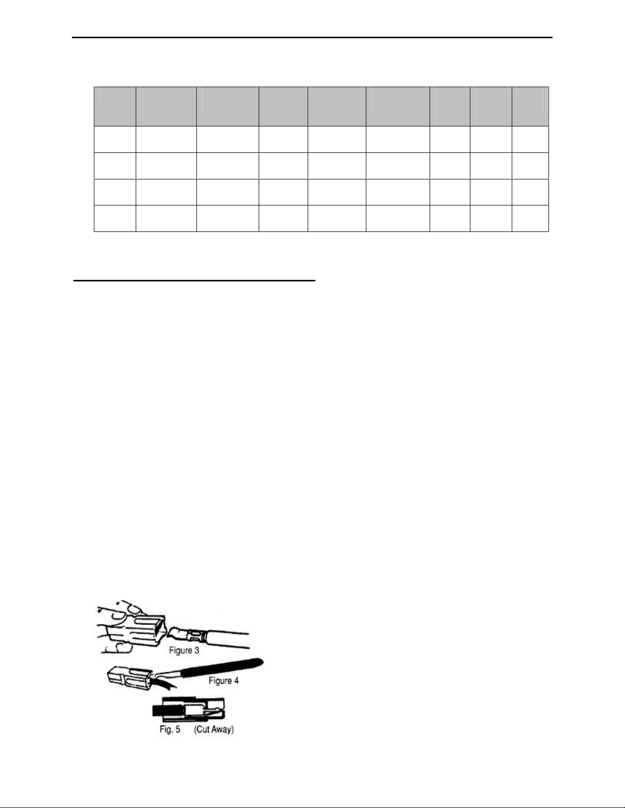
Fig 3: Correct orientation of terminal and
housing.
Fig 4: Using an insertion tool to snap
terminal in place. A very small, flat-blade
screwdriver will work.
Fig 5: Assembled terminal and housing.
2
 Loading...