

Page 1

MFJ cub QRP CW Transceiver Operation Manual
1
INTRODUCTION
Congratulations on purchasing the MFJ cub Transceiver. The cub takes
advantage of SMD technology to achieve big-radio performance in a pocketsized package. Whether you're taking a 10-minute DX break from the
computer, or backpacking in the mountains, the cub is a great way to put the
magic back into ham radio. Here are a few of the features we think you'll
appreciate:
Hot Receiver: Pulls in weak QRP signals.
Low Noise: Virtually no noise contribution from receiver electronics.
Sharp Passband: Ladder filter and shaped audio reject unwanted QRM and
QRN.
Differential-Mode AGC: Audio output holds steady over 80-dB signal range.
Robust AF Output: 100 mW AF amp drives headphones and speakers with
ease.
Adjustable Transmitter: Power output continuously variable for QRP.
Full QSK: Seamless electronic switching for smooth break-in.
Natural Sidetone: Receiver monitors actual on-air signal.
Shaped Keying: Controlled envelope for click-free keying.
Custom Set-up: Transmit offset and receiver passband both user adjustable.
Low Power Drain: Runs from any lightweight regulated power source.
Truly Portable: Set up anywhere and tuck out of the way when not in use.
Simple to Use: Off/on switch, volume control, and tuning knob--that's it!
Attractive: Rugged aluminum case looks good, and it's built to last.
Ergonomic Layout: Controls conveniently positioned.
Page 2

MFJ cub QRP CW Transceiver Operation Manual
2
TYPICAL SPECIFICATIONS
Cub models are available for six popular QRP bands. Typical performance for
each is shown in the following table:
Model
VFO
MHz
Tuning
kHz
IF Freq
MHz
-6dB
Selectivity
MDS
Selectivity
USB
dB
Power
W*
Spurs
dBc
9315
9 50 12 750 <.3uV -38 1.0 -40
9317
8.06 50 10 600 <.3uV -45 1.5 -40
9320
4 60 10 600 <.3uV -45 2.0 -40
9330
4.1 20 6 350 <.3uV -56 2.0 -40
9340
5 60 12 750 <.3uV -38 2.2 -40
9380
6 60 10 600
*RF power output at 13.8 Vdc supply voltage.
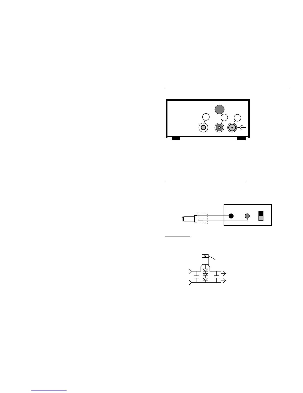
CONTROL LOCATIONS AND FUNCTIONS
TUNE
VOLUME
Power
1
2
3
4
5
PHONES
MFJ cub
QRP CW Transceiver
1. Power LED: Indicates when transceiver is turned on.
2. Power Switch: Applies power to transceiver.
3. Phone Jack: Accepts 3.5 mm stereo headphone jack (stereo wiring).
4. Volume Control: Adjusts volume to comfortable level.
5. VFO Tuning: Selects transceiver's operating frequency.
Page 3
MFJ cub QRP CW Transceiver Operation Manual
3
MFJ Enterprises
Starkville, MS USA
78
Model MFJ-93xx
xx Meter
QRP CW Transceiver
6
Key Antenna
Power
+
-
6. Key Jack: Accepts 3.5 mm plug from key or keyer, mono wiring.
7. Antenna Jack: Accepts RCA plug from 50 ohm antenna.
8. Power Jack: Accepts 5.5 mm OD, 2.1 mm ID coaxial plug, (+) to center.
QUICK-START OPERATING INSTRUCTIONS
Power Sources: The cub requires a regulated 12-14 VDC source capable of
delivering 400 mA. Power connection requires a 5.5 mm x 2.1 mm coaxial plug
(use Radio Shack 274-1567). Wire (+) voltage to center terminal, and (-) to
common.
+
-
Power Supply+
-
Important Note: Unregulated DC sources--wall cubes, solar panels, etc.--may
damage your radio. A simple regulator circuit, like the one shown below, will
provide protection. Note that U1's heat sink is 1.8 V above ground and must be
isolated.
-
+
+
-
C1
D1-D3
C2
U1
U1 - 7812 Regulator
D1-D3 - 1N4001 Diode
C1-C2 - .1 uF
13.8 V Reg.
Unregulated
Source
Parts
15 - 28 V
Attach heatsink here
Page 4
MFJ cub QRP CW Transceiver Operation Manual
4
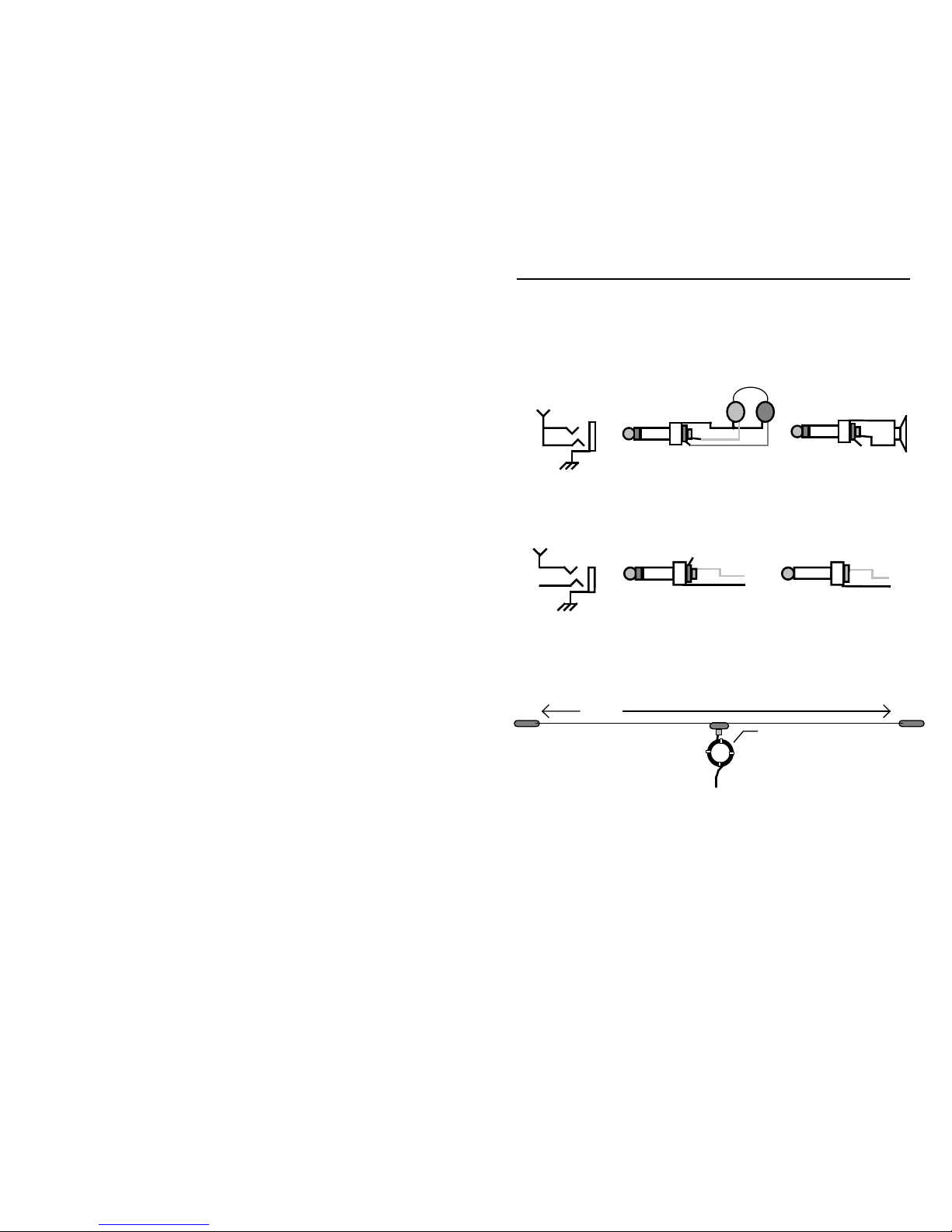
Headphones: Use standard walkman-type stereo headphones exhibiting 8-40
ohms impedance (higher-quality headsets often yield better performance).
Alternatively, plug in any extension speaker with a similar load impedance. Be
sure to use only stereo type plugs--a mono plug will short the radio's audio
output to ground!
NC
Audio Line
Keys and Keyers: Use any hand key or electronic keyer with a 3.5 mm plug
(mono or stereo plug okay). Connect the key line to the jack's tip and the
common line to the sleeve.
NC
Key Line
NC
Stereo Plug
Mono Plug
Key
Key
Antennas: The cub is designed to work with any efficient 50 ohm antenna
exhibiting a VSWR of 2:1 or less. Suggested dipole lengths are shown in the
following diagram, along with data for adding a simple coaxial choke-type
balun:
17 Meters: 25' 10"
15 Meters: 22' 2"
20 Meters: 33' 2"
30 Meters: 46' 4"
40 Meters: 65' 10"
80 Meters: 130'
Length
Coax Balun
17 Meters: 7', 8 turns
15 Meters: 6', 8 turns
20 Meters: 8', 8 turns
30 Meters: 10', 7 turns
40 Meters: 15', 6 turns
80 Meters: 20', 8 turns
RG8X or RG58
For best performance with any antenna, install as high and in the clear as
possible. The ARRL Antenna Handbook, The ARRL Antenna Compendium, and
many other amateur publications--including several from MFJ--offer additional
antenna tips and suggestions.
Page 5

MFJ cub QRP CW Transceiver Operation Manual
5
Antenna Connection: The cub uses either a RCA antenna jack or the optional
chassis-mounted BNC connector (mounting hole provided). For a direct
transition from RCA to standard UHF (PL-238) connectors, use a Radio Shack
scanner-adapter plug RS278-208. Shorten the center pin--as shown--for easier
insertion and removal.
Cut here and smooth off tip with a file.
RS 278-208
UHF to
Motorola
Adapter
BNC-to-UHF transitions are also readily available if the optional BNC jack is
installed.
Adjusting Power Output: The small hole in the center of the cub's cover
provides access to a power-level trimpot (R19). For low power (QRP), adjust
this trimpot counter-clockwise (CCW) with a small screwdriver while observing
output on a QRP-type power meter. To increase power, turn the trimpot
clockwise (CW). When resetting the cub for full power, note that output will
increase rapidly then reach a plateau where it levels off. Adjust R19 only to the
point where the power increase begins to level off. Attempting to wring the last
few milliwatts from your radio by turning the trimpot fully clockwise will only
overdrive the transmitter mixer stage and add unwanted spurious products to
your signal.
GETTING INVOLVED WITH QRP
Technically speaking, operating QRP means limiting your transmitter power to
below 5 watts on CW or below 10 watts PEP on sideband. However, for a
growing number of licensed amateurs, the "QRP" moniker symbolizes a return
to the basics of radio--with a strong emphasis on operating skills,
experimentation, home construction, and fraternity. Spanning a continent or
hopping oceans with less energy than it takes to illuminate a night light is not
only exciting, it borders on the miraculous. Yet, QRP enthusiasts do it every
day--often using simple home-built equipment running only microwatts of
power. Even staunch QRO contesters have succumbed to the lure and challenge
of QRP, revisiting DXCC while running 5 Watts or less. For many, operating
"QRP" restores that special sense of personal achievement that's too easily lost
when high-tech appliances invade the ham shack. Regardless of motivation, this
particular segment of the ham radio community is growing steadily and
continues to thrive as other techno-fads come and go.
Page 6

MFJ cub QRP CW Transceiver Operation Manual
6
QRP Calling Frequency: To meet up with other low-power enthusiasts, try
operating on the QRP International Calling Frequencies. These are popular
gathering places for people who share your interest in QRP activities:
80 Meters: 3.560 MHz (3710 Novice)
40 Meters: 7.040 MHz (7.110 Novice)
30 Meters: 10.106 MHz
20 Meters: 14.060 MHz
15 Meters: 21.060 MHz
QRP-A.C.R.I.: To learn more about QRP activities, your best resource is QRP
Amateur Radio Club International (or QRP-A.R.C.I.), a worldwide organization
supporting low-power operation and home construction. This popular group
sponsors several contests a year, publishes QRP Quarterly Magazine, and
coordinates an annual QRP conference in tandem with Dayton Hamvention.
You can find QRP-A.R.C.I. on the World Wide Web at www.qrparci.org. They
also provide links to local and regional QRP clubs around the world, plus links
leading to a wealth of operating and technical information.
QRP DX Operating Tips: Competing with more powerful stations to capture
QSLs from rare DX prefixes requires patience and good operating skills. Here
are 10 tricks-of-the-QRP-trade you can use with your cub to land the tough
ones!
1. Hunt and pounce! There's never a pileup if you're the first one there.
2. Seek out and answer CQs (as opposed to repeatedly calling CQ).
3. Add /QRP to the end of your call. Let others know you're running low
power.
4. Answer CQs from weak stations as well as strong--they may be QRP too.
5. Be patient in pileups. You'll get the same QSL whether you're first or last
in line!
6. Use QSB and band swings to advantage. When they get stronger, you
might too!
7. Look before you leap. Wait for a lull to sneak in your call.
8. Move up or down from the pileup. Being on the edge helps your signal
stand out.
9. Call DX stations as they wrap up QSOs (but not over the other station's
final).
Page 7

MFJ cub QRP CW Transceiver Operation Manual
7
10. Pay attention to DX forecasts. When the band is hot, power differences
matter less.
CIRCUIT DESCRIPTION
In receive, Chebechev filter L1-L2 preselects incoming signals. U2 converts
signals to the IF using its internal LO as a varactor-tuned VFO. IF amp Q1
drives ladder filter Y1-Y3. Product detector U3 recovers the AF product, using
its internal LO as a crystal-controlled BFO. Audio is then routed to AF
amplifier U4 through differential attenuator Q3. U4, which is EQ'd for CW,
selectively amplifies signals to speaker-level. Level detector D3 samples U4
output and returns a AGC signal to attenuator Q3. Volume is controlled by a
resistive attenuator downstream of the level detector. The receiver remains on
in transmit mode to provide CW sidetone.
BPF
IF Amp
AGC
Atten.
Det
Rx Mxr
VFO
LO
Prod. Det AF Amp
U4
Tune
Vol
Ladder
Filter
U2 U3Q1Q3Y1-Y3
L1,L2
U5
Buffer
Pwr
Tx
Tx Mxr
Offset
BPF
L6,L7
Q5
Q6
BFO
Q4
+T +R
Q8
Q9
Key
Q2
T/R
D4-D7
L10-L11
Antenna
Phones
AGC
Q7
Driver
PA
U1
+V
+ Reg
T/R
Pwr
Sw1
BFO
Freq.
Tx
CR1
Regulator
D3
D1
C27
C40
R19
In transmit, buffer Q4 samples U2's VFO signal and feeds it through attenuator
R19 to transmit mixer U5. Q5 boosts U5 output, and Chebechev filter L6-L7
selects the desired mixer product. Driver Q6 boost the filtered signal and feeds
it through an L network to class-C PA amplifier Q7. +T switch Q8 is keyed to
generate CW characters. This powers U5, Q5, and the bias line to Q6. Pi-filter
L10-L11 reduces transmitter harmonic content.
On key-down, antenna switch D4-D7 is biased open by Q8. Also, Q2 is biased
into conduction by Q9--pulling the receiver input to ground. These two gates
Page 8

MFJ cub QRP CW Transceiver Operation Manual
8
produce -75 dB port isolation, allowing the receiver to monitor the transmitted
signal without overload. Crowbar diode D1 protects circuitry from reversepolarity power connection, and LED CR1 indicates when the radio is on.
Construction is hybrid, employing a mix of SMD and conventional "throughhole" components to reduce size and increase reliability.
IN CASE OF DIFFICULTY
If you experience a problem with your cub, look through the checklist below to
determine if it's something simple you can fix yourself. If that fails to resolve
the problem, you may contact MFJ Technical Service at 662-323-0549 or the
MFJ Factory at 662-323-5869. You will be best helped if you have your unit,
manual and all information on your station handy so you can answer any
questions the technicians may ask.
You can also send questions by mail to MFJ Enterprises, Inc., 300 Industrial
Park Road, Starkville, MS 39759; by Facsimile to 662-323-6551; or by email to
techinfo@mfjenterprises.com. Send a complete description of your problem, an
explanation of exactly how you are using your unit, and a complete description
of your station.
Won't Power Up: Check power source and associated cables/plugs. Check
reverse-polarity fuse (pc trace behind power jack). If blown, replace with loop
of #32 wire.
No Signals Heard: Check antenna and feedline for breaks and shorts. Is the
band dead? Try a different antenna.
Unwanted Signals: Intermod from strong BCI may be overloading the
frontend. If using a large multiband antenna, try a smaller monobander. Also,
check station ground.
Intermittent Audio: Check headphones or extension speaker and cord/plug.
No Transmit: Check key or keyer and its cord/plug. Is the keyer battery okay?
Sidetone, But No RF Out: Is R19 turned down? Check patch cord to power
meter.
Page 9

MFJ cub QRP CW Transceiver Operation Manual
9
MFJ CUB ALIGNMENT AND SERVICE NOTES
1
3
2
4
5
6
1. BFO Trim (set for 600-Hz LSB passband center)
2. VFO Cal (set for desired CW band segment)
3. Rx BPF (tune for maximum sensitivity)
4. Tx Offset (set for 600-Hz sidetone pitch)
5. Power (set for onset of gain compression)
6. Tx BPF (tune for maximum power output)
Alignment Control Function
Important Note: If you lack the necessary test equipment and skills to make
these adjustments, seek assistance from a qualified technician. Misalignment
will degrade transceiver performance and may also result in spurious out-of-band
operation in violation of FCC rules. MFJ cannot be held responsible for
transceiver misalignment in the field.
Voltage Chart: Voltage charts are useful for diagnosing circuit problems and
isolating component failures. Any voltage variation of 10% or more may
indicate a problem.
Important Note: Exercise caution when testing SMD circuitry with conventional
bench probes. If the voltmeter probe shorts to adjacent pins during the
measurement, component damage may result. If you lack the tools and training
to troubleshoot SMD circuitry, seek assistance.
Transistor Voltages
Q1 Q2 Q3 Q4 Q5* Q6* Q7 Q8 Q9
E/D
0 --- --- 13.8 --- --- --- 13.8 12.8
B/S
0.7 --- --- 2.7 0.7 0.3 --- 13.3 13.5
C/G
8.3 13.8 --- --- 8.3 13.8 13.8 0.4 13.8
*Voltage values obtained with radio in transmit mode. Do not place test probe on Q7 during
transmit--RF may damage meter.
Page 10

MFJ cub QRP CW Transceiver Operation Manual
10
IC Voltages
Pin U1 U2 U3 U4 U5*
1
7.9 1.4 1.4 1.3 1.4
2
0 1.4 1.4 --- 1.4
3
0 0 0 --- 0
4
--- 4.2 4.3 0 4.7
5
--- 4.2 4.3 7.2 4.7
6
0 5.4 5.5 13.8 5.8
7
0 4.9 5.1 7.0 5.5
8
13.8 5.5 5.5 1.4 5.9
Component Pinout:
SO-8
IC Package
1 2 3 4
8 7 6 5
SOT-23 Transistor Package
Style 6
C
BE
Style 21
Style 10
GSDDS
G
SA602
LM386
78L09
2N3904
2N3906
2N2222
2N7002
J310
1N914
A
C
N.C.
E
B
C
(Top)
2N5109
(case)
Page 11

MFJ cub QRP CW Transceiver Operation Manual
11
PARTS PLACEMENT
Page 12

MFJ cub QRP CW Transceiver Operation Manual
12
SCHEMATIC
Page 13

MFJ cub QRP CW Transceiver Operation Manual
13
NOTES
 Loading...