

Page 1
Page 2

MFJ-222 Antenna Phase Meter Instruction Manual
Table of Contents
Specifications.................................................................................................................. 1
Front Panel......................................................................................................................1
Top Panel........................................................................................................................1
Setup...............................................................................................................................2
Power Source ........................................................................................................................................2
Contrast .................................................................................................................................................2
Operation ........................................................................................................................2
Theory of Operation ........................................................................................................3
Calibration....................................................................................................................... 3
Schematic .......................................................................................................................4
FULL 12-MONTH WARRANTY.......................................................................................5
DISCLAIMER
Information in this manual is designed for user purposes only and is not intended to supersede
information contained in customer regulations, technical manuals/documents, positional handbooks, or
other official publications. The copy of this manual provided to the customer will not be updated to reflect
current data.
Customers using this manual should report errors or omissions, recommendations for improvements, or
other comments to:
MFJ Enterprises,
300 Industrial Park Road,
Starkville, MS 39759.
Phone: (662) 323-5869
FAX: (662) 323-6551.
Business hours:
M-F 8:00 AM-4:30 PM CST.
© 2012 MFJ Enterprises, Inc.
ii
Page 3

MFJ-222 Antenna Phase Meter Instruction Manual
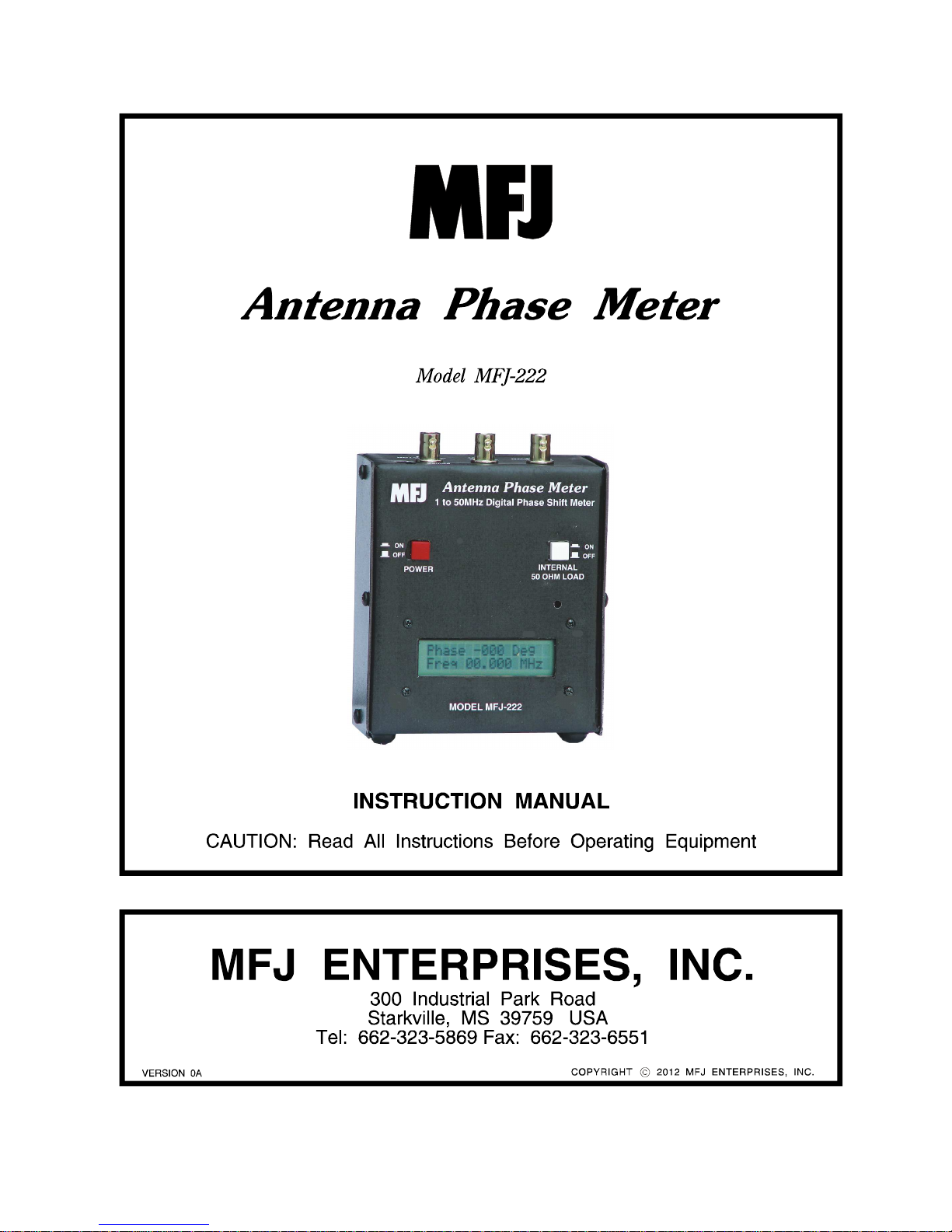
Antenna Phase Meter
Phase Cal
-
+
Introduction
The MFJ-222 is an Antenna Phase Meter designed to measure network phase shifts. This could be for
antenna phasing networks or any other network that you need to know the phase shift of. The MFJ-222
uses low power high speed devices giving it a large bandwidth for any HF or lower VHF network and long
battery life for field use. A built in internal load is featured to reduce the use of adapters and loads in
many cases. An easy to read LCD display is used for reading phase measurements to the degree and the
frequency to 1KHz.
Specifications
Phase meter
Frequency Range 1KHz to 55MHz
Phase Range -180 to 180 degrees
Frequency Counter 300KHz to 50MHz
Input Signal Level 1V to 3.5V with Internal Load
1V to 16V internal load off
Supply Voltage 8 to 16VDC External supply
9V Battery Internal supply
Front Panel
The front panel has only 2 main controls the
POWER and the INTERNAL LOAD push button
1 to 50MHz Digital Phase Shift Meter
switches. The LCD Display shows the Phase
from -180 to 180 degrees and the frequency of
the generator being used on the MFJ-222.
ON
OFF
POWER INTERNAL
50 OHM LOAD
There are 2 adjustment ports that once set are
not normally readjusted which are the Phase
Cal and the Display Contrast controls.
Display
Contrast
Phase -000 Deg
Freq 00.000 MHZ
MODEL MFJ-222
Top Panel
The top panel has the signal connections using BNC connectors and the power jack which is a 2.1MM
connector.
The GENERATOR IN is the input for the signal generator.
UNKNOWN
IN
REF
OUT
POWER
9-15VDC
GENERATOR
IN
The output should be at least 1V and no more than around
3.5V (250mW) if the internal 50 ohm load is used.
The REF OUT is the output to the device under test.
The UNKNOWN IN is from the output of the device under test
to the MFJ-222 Phase Meter.
© 2012 MFJ Enterprises, Inc. 1
Page 4

MFJ-222 Antenna Phase Meter Instruction Manual
Setup
Power Source
The MFJ-222 can operate on an internal 9 volt battery or an external power source between 8 and 16
volts. To install the battery remove the screws on the sides holding on the back cover and snapping in a
9V battery. Reinstall the cover. Removal of the battery is not required when operating on external power.
The MFJ-222 will not recharge a rechargeable 9V battery. If rechargeable batteries are used they will
have to be removed and charged in an external charger.
Contrast
The only setup that should have to be done is to adjust the contrast by turning the trim pot in the Display
Contrast hole till the contrast is set to your preference using a tuning tool or small screw driver.
Operation
The basic method of operation is to connect a generator such as an MFJ-259B Antenna Analyzer to the
GENERATOR INPUT. Connect a short cable from the REF OUT to the device under test input. Then
connect a short cable from the device under test output to the UNKNOWN INPUT of the MFJ-222. The
phase shift between the REF OUT and the UNKNOWN IN will be measured. Assuming that the device
under test is expecting a 50 ohm load, turn on the internal load on the MFJ-222. If the device under test is
not expecting a 50 ohm load then a BNC TEE should be connected to the UNKNOWN IN port and the
device under test to one leg of the Tee and the expected load on the other side of the Tee.
One of the uses of the phase meter is to measure and adjust phasing networks for antenna systems. The
system can be as simple as a piece of coax the length needed to shift the phase needed or a complex LC
network for a steerable array. When both ends of the network are accessible together setup would be like
the figure above with the coax or network as the device under test. Amplifiers and filters can also be
tested in this method. The cables should be as short as practical and the phase shift due to the test
cables should also be measured to compensate for their phase shift.
CAUTION
Do not transmit into the MFJ-222 Antenna Phase Meter. It is not designed to be used with high power test
signals.
© 2012 MFJ Enterprises, Inc. 2
Page 5

MFJ-222 Antenna Phase Meter Instruction Manual
Signal Generator
A second method of phase shift measurement is where the ends are not easily accessible. In this mode 2
cables of equal phase shift (preferably the same type and length) are needed so they can reach the
points to measure. In this case the signal generator should be feeding reference measurement point
directly to keep from having to compensate for the long jumper cables used although if the phase shift of
the jumper cables are taken into account then it
could be fed at the GEN IN port on the MFJ-
222. The diagram shows a two vertical array
with a phasing network. In this case the
antennas provide the load so the internal load is
turned off. T connectors with the proper
adapters would be used to tap into the lines at
the antennas and the phase between the two
would be displayed.
Phase Shift Network
Feed
Point
Theory of Operation
The MFJ-222 takes the signal from the generator and sends it to the device to be tested. The signal is
passed through the device and brought back in to the MFJ-222. A dual high speed low power comparator
is used to square up the signal at the zero crossing point of the sine wave for both the REF OUT and
UNKNOWN IN signals. Those signals are fed into a 2 input high speed XOR logic IC and the ratio of the
off to on time is integrated and measured with one of the analog inputs of a PIC microprocessor. The
voltage is at maximum at a 180 degree phase shift. The outputs of the comparators are also fed to a high
speed D Flip-Flop to determine which input is the leading pulse and determine the phase of the signal. A
second XOR gate is used to take the reference comparator output and drive one of the PIC counter
registers to measure the frequency. The exact voltage levels are not critical. It is recommended that 1V
peak to peak be used to reduce the jitter that may be encountered at lower levels. With the internal load
enabled the upper limit is with the power dissipation of the load. With the load off higher levels can be
used.
Calibration
A simple method of calibration is to use a 10 to 20 foot long piece of 50 ohm cable between the REF OUT
and the UNKNOWN IN ports. Sweep the generator frequency to where the phase is shifted 180 degrees.
That point is indicated when the plus and minus sign flickers back and fourth. At that point adjust the
Phase Cal pot to read 180 degrees. For a 10 ft piece of RG-58 the frequency is around 36 MHz.
© 2012 MFJ Enterprises, Inc. 3
Page 6

MFJ-222 Antenna Phase Meter Instruction Manual
Schematic
© 2012 MFJ Enterprises, Inc. 4
Page 7

MFJ-222 Antenna Phase Meter Instruction Manual
FULL 12-MONTH WARRANTY
MFJ Enterprises, Inc. warrants to the original owner of this product, if manufactured by MFJ Enterprises,
Inc. and purchased from an authorized dealer or directly from MFJ Enterprises, Inc. to be free from
defects in material and workmanship for a period of 12 months from date of purchase provided the
following terms of this warranty are satisfied.
1. The purchaser must retain the dated proof-of-purchase (bill of sale, canceled check, credit
card or money order receipt, etc.) describing the product to establish the validity of the warranty
claim and submit the original or machine reproduction of such proof of purchase to MFJ
Enterprises, Inc. at the time of warranty service. MFJ Enterprises, Inc. shall have the discretion to
deny warranty without dated proof-of-purchase. Any evidence of alteration, erasure, of forgery
shall be cause to void any and all warranty terms immediately.
2. MFJ Enterprises, Inc. agrees to repair or replace at MFJ's option without charge to the
original owner any defective product provided the product is returned postage prepaid to MFJ
Enterprises, Inc. with a personal check, cashiers check, or money order for $12.00 covering
postage and handling.
3. MFJ Enterprises, Inc. will supply replacement parts free of charge for any MFJ product
under warranty upon request. A dated proof of purchase and a $8.00 personal check, cashiers
check, or money order must be provided to cover postage and handling.
4. This warranty is NOT void for owners who attempt to repair defective units. Technical
consultation is available by calling (662) 323-5869.
5. This warranty does not apply to kits sold by or manufactured by MFJ Enterprises, Inc.
6. Wired and tested PC board products are covered by this warranty provided only the
wired and tested PC board product is returned. Wired and tested PC boards installed in the
owner's cabinet or connected to switches, jacks, or cables, etc. sent to MFJ Enterprises, Inc. will be
returned at the owner's expense un-repaired.
7. Under no circumstances is MFJ Enterprises, Inc. liable for consequential damages to
person or property by the use of any MFJ products.
8. Out-of-Warranty Service: MFJ Enterprises, Inc. will repair any out-of-warranty product
provided the unit is shipped prepaid. All repaired units will be shipped COD to the owner. Repair
charges will be added to the COD fee unless other arrangements are made.
9. This warranty is given in lieu of any other warranty expressed or implied.
10. MFJ Enterprises, Inc. reserves the right to make changes or improvements in design or
manufacture without incurring any obligation to install such changes upon any of the products
previously manufactured.
11. All MFJ products to be serviced in-warranty or out-of-warranty should be addressed to
MFJ Enterprises, Inc., 300 Industrial Park Rd, Starkville, Mississippi 39759, USA and must
be accompanied by a letter describing the problem in detail along with a copy of your dated proofof-purchase and a telephone number.
12. This warranty gives you specific rights, and you may also have other rights, which vary
from state to state.
© 2012 MFJ Enterprises, Inc. 5
Rev 04/08/2011
Page 8

MFJ-222 Antenna Phase Meter Instruction Manual
© 2012 MFJ Enterprises, Inc.
 Loading...