

Page 1

SCRIBE EC Installation Guide
Document Revision: 11/4/04
Minimum System Requirements for Scribe EC With Opti Ec
Print Station & 1-Drive Models – Minimum System Requirements:
• Minimum Pentium® III or compatible personal computer @ 800 MHz or faster
• Windows 2000 Professional (Service Pack 4 or higher) or Windows XP Pro Service Pack 1.0a or higher
• 512 MB RAM
• 7200 RPM ATA-100 hard drive with 850 MB for CD-R or 5GB (NTFS) for DVD-R
of free hard disk space - fully defragmented
• Monitor: 800 x 600 display, 16-bit color recommended
• Two button mouse
• High quality recordable CD-Rs / DVD-Rs
• One free PCI slot for 1 Drive System, Not required for Print Station Only.
• One external COM Port (COM1 or COM2) *Two external COM ports are needed if
using MF DIGITAL Spectrum2 or Prism Plus (COM1 and COM2).
• WinASPI driver layer (Included)
• IEEE-1394 B Adapter (Included)
Appropriate IEEE-1284 printer cable if attached
•
* A USB to Serial Converter can be used if no COM port is available.
•
2-Drive & 4-Drive Models – Minimum System Requirements:
• Minimum Pentium® 4 or compatible personal computer @ 2 GHz or faster
• Windows 2000 Professional (Service Pack 4 or higher) or Windows XP Pro Service Pack 1.0a or higher
• 1 GB RAM (Asynchronous Operation)
• 7200 RPM ATA-100 hard drive with 850 MB for CD-R or 5GB (NTFS) for DVD-R
of free hard disk space - fully defragmented
• Monitor: 800 x 600 display, 16-bit color recommended
• Two button mouse
• High quality recordable CD-Rs / DVD-Rs
• One free PCI slots
• One external COM Port (COM1 or COM2) *Two external COM ports are needed if
using MF DIGITAL Spectrum2 or Prism Plus (COM1 and COM2).
Page 2
IF YOU PURCHASED A PRINT STATION – SKIP THIS PAGE
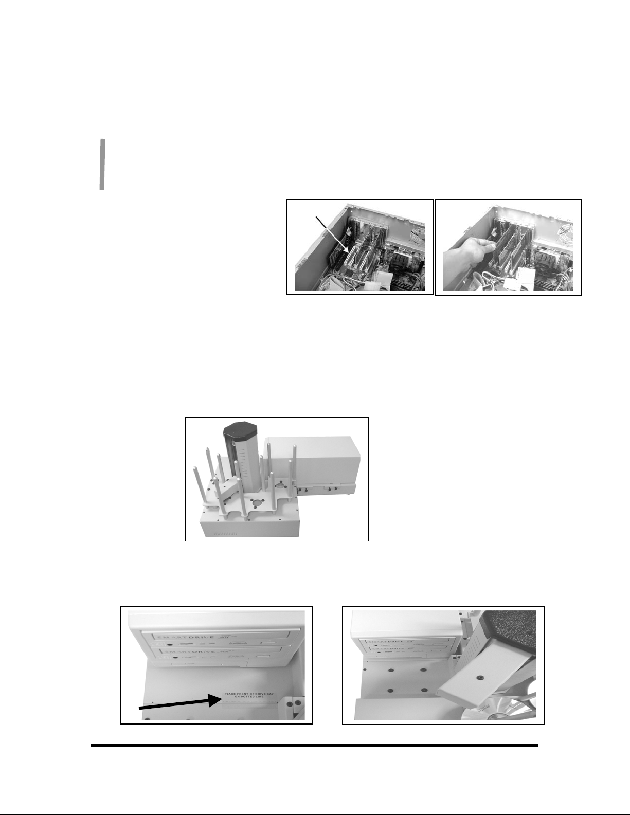
Installing the Firewire Adapter Card
One and two drive ScribeECs require one
IEEE-1394 card. Four drive systems require
two IEEE-1394 cards.
1. Shut down the PC.
2. Turn the PC’s power off.
3. Unplug the PC.
4. Remove the PC’s cover as
5. Locate an empty PCI slot, as
6. Install the firewire adapter card (fig. 2).
You should never attempt to service a unit without ensuring proper anti-static protection. The
use of a grounding strap, or other such grounding device, is advised. In addition, the internal
configuration of your computer may be different from the computer pictured below.
indicated in the PC’s manual.
seen in (fig.1).
(fig. 2)(fig. 1)
Installing the Drive Bay
1. Place the drive bay onto the base unit as seen in (fig. 1).
2. Position the drive bay so that the front right corner sits over the dotted line (fig. 2). Proper position is
shown in (fig. 3).
(fig.1)
(fig. 2)
(fig. 3)
Page 2
Page 3
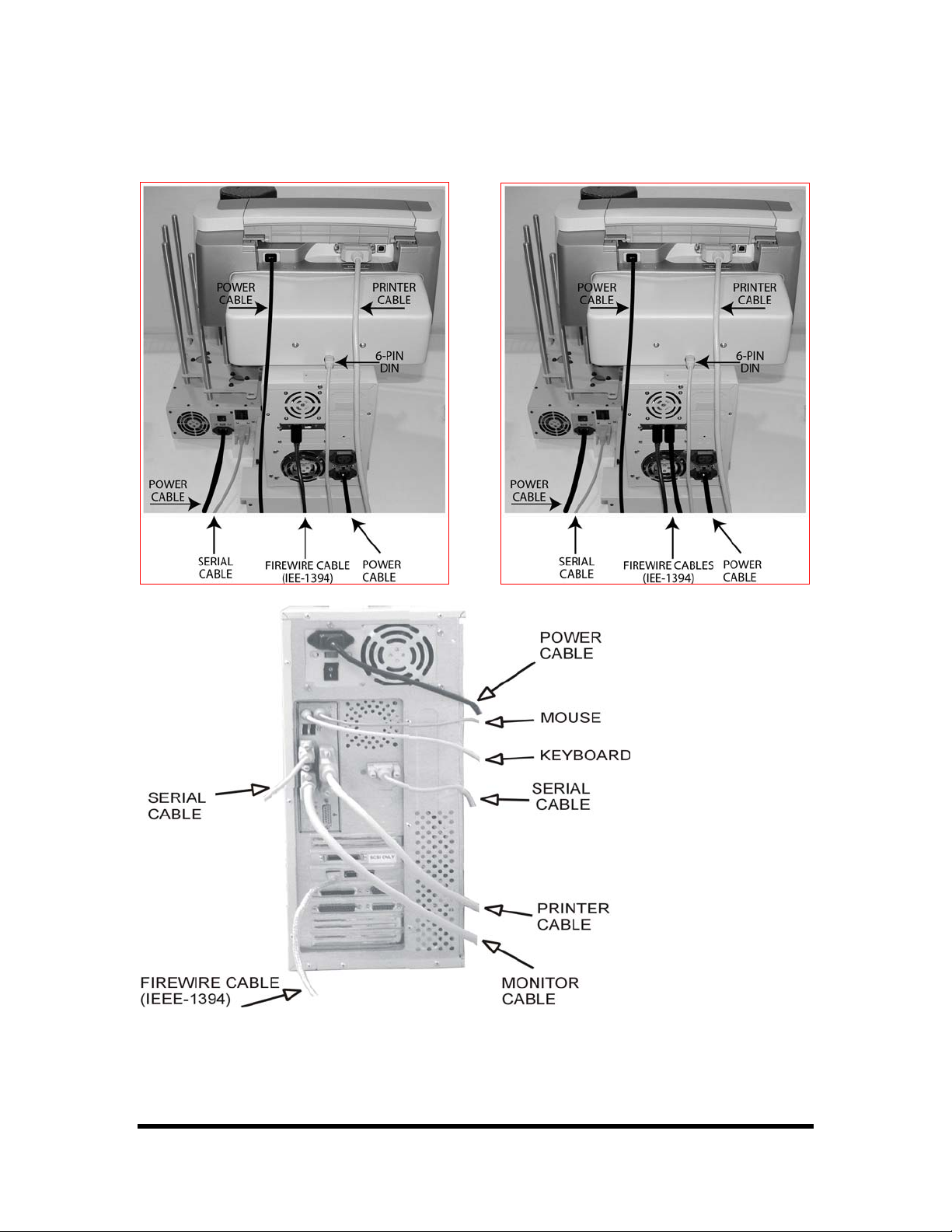
Making the Connection
1 & 2 Drive Systems 4 Drive System
PC Connection
Two drive unit uses one fire wire adapter card and one cable.
Four drive unit uses two firewire adapter cards and two cables… Install one cable in each
firewire card.
Page 3
Page 4

Installing the SCRIBE EC Software
1. Insert the SCRIBE EC
software CD.
2. From the CD ROM drive of
the computer, click Install
SCRIBE Software.
3.
Click Next (fig. 1).
4. Accept the license agreement
and click Next (fig. 2).
5. Click Install (fig. 3).
6. Click Finish (fig. 4).
(fig. 1)
(fig. 2)
(fig. 3)
(fig. 4)
Page 4
Page 5

Installing the SCRIBE EC Alignment Utility for Aligning the Drive
Tower
1. Insert the SCRIBE CD into the CDROM drive of your PC.
2. Click on setup.exe of the alignment
utility and Click OK (fig. 1).
3. Click the button indicated in (fig. 2).
4. Enter a name for the group where
the Alignment Utility will be
located. Click Continue (fig. 3). The
Scribe Program Utility will appear
under Start / Programs / ”group
name” after installation is
complete.
5. A progress bar will appear (fig. 4).
6. Click OK (fig. 5) to finish
installation.
(fig. 1)
(fig. 2)
(fig. 3)
(fig. 4)
(fig. 5)
Page 5
Page 6

Installing the OptiEC Printer Driver
1. Click Start-> Settings-> Printers
2. Click Add New Printer
3. The “Welcome to the Add Printer
Wizard” window will appear (fig 1).
Click Next.
4. In the “Local or Network Printer”
window, uncheck the “Automatically
detect installed printer” option ,
leaving the “Local printer attached to
computer” option (fig 2) and click
Next..
5. In the “Select a Printer Port” window,
leave the default as LPT1 (fig 3) and
click Next.
6. In the “Install Printer Software”
window, click the “Have Disk” button
(fig 4). You will then be prompted to
“Install from Disk”, click the
“Browse” button (fig 5). Select the
location of the printer driver from
your CD-ROM drive in the PC (fig 6).
fig 1
fig 2
fig 3 fig 4
fig 5
fig 6
Page 6
Page 7

Installing the MF Digital OptiEC Printer Driver (cont.)
7. After specifying the driver for the MF
Digital OptiEC printer, the printer “MF
Digital OptiEC” will appear in the “Add
Printer Window” (fig 7). Click Next to
continue.
8. In the “Name your Printer” window,
leave the printer as the default name, and
select the printer to be the default printer
(fig 8) and click Next.
9. In the “Printer Sharing” window, select
“Do Not Share the Printer” (fig 9) and
click Next.
10. Say No to “Print Test Page” (fig 10)
and click next.
11. The “Completing the Add Printer
Wizard” window will appear (fig 11).
Click Finish. After clicking finish, the MF
Digital OptiEC printer driver will be
installed. You will be asked to accept that
the printer driver is not digitally signed by
Microsoft, click Continue (fig 12). You
have now successfully installed the printer.
fig 7
fig 8
fig 10
fig 9
fig 11
fig 12
Page 7
Page 8

Pri
Adjusting the MF Digital OptiEC Printer Driver Settings
nter Spooling
It is important to disable printer spooling on the MF
Digital OptiEC printer. To do so, please follow the
steps below:
1. Go to Start-> Settings -> Printers
2. Right-click on the MF Digital OptiEC
printer in the Printers Folder
3. Go to Properties
4. Go to the Advanced Tab
5. For the Scribe Program to use the printer
effectively, please match the settings of
your printer driver to the example on the
right-side of this page.
6. To save settings, Click Apply and OK to
exit.
***NOTE: Any changes made to the printer
driver settings, require a NEW PRN file to be
made. If you change one of the settings, be sure
to create a NEW PRN file.***
Page 8
Page 9

C
d
d
r
r
d
Aligning the Drive Tower
1. From your Start Menu Open the SCRIBE E
Alignment Utility (fig. 1). It will be located in
the folder designated when you installed the
alignment utility. Choose the appropriate COM
Port which the Scribe EC Loader is installe
on. Select all other printers and drives, an
Click Start Test.
Follow the instructions by opening the top
2.
CD/DVD drive tray, and Clicking Yes (fig. 2).
The picker arm will hover a disc over the drive
tray, observe the discs position and make the
adjustments to the drive tower (fig. 3).
Click Yes when you are satisfied with you
3.
adjustment (fig. 4).
4. The picker arm will then place the disc onto
the drive tray. Follow the on screen
instructions and click OK (fig. 5).
5. Once you are satisfied with the drive towe
alignment, tighten the thumb-screws locate
on both sides of the drive tower (fig. 6).
(fig. 1)
(fig. 2)
(fig. 3)
(fig. 4)
(fig. 5)
(fig. 6)
Page 9
Page 10

C
p
d
g
r
t
r
f
p
p
Aligning the MF Digital OptiEC Printer
Alert:
1. From your Start Menu Open the SCRIBE E
Before starting the Alignment Utility,
osition the front end of the printer plate
on the dotted line of the drive tower.
Software.
Once the Scribe EC Software opens, click on
2.
the Settings tab.
Click Change Settings and select the MF
3.
Digital OptiEC Printer. After making this
selection, you will need to restart the Scribe
EC Software program.
4. After restarting the Scribe EC Software
rogram, go to the Settings Tab. You will now
see a button that says “Test Loading an
Unloading the Printer”. Click this button. (fi
1)
5. A Printer Alignment Box will appear. First,
you will click the “Pick up a disc from the
Input spindle and put it down on the printe
tray” (fig 2). Adjust the printer so that the CD
is aligned in the printer tray (fig 3).
After ensuring proper placement of the CD on
6.
the printer, continue with the Alignmen
Utility and pick up the CD from the printe
tray.
After you are satisfied with the alignment o
7.
the CD on the printer tray, lock the printer in
lace by tightening the thumb screws on the
printer plate to hold the printer in place.
(fig 1)
(fig 2)
(fig. 3)
Page 10
 Loading...