

Page 1

AP-1301 Operator’s Guide
Page 2

AP-1301 i/t Operator’s Guide
Document Revision: 100102
Copyright Notice
Copyright ©2002 by MediaFORM, Inc. USA. All rights reserved.
This manual and the accompanying illustrations may not be copied, reproduced,
electronically transmitted, or tra nslated into another language, in whole, or in par t,
without the written consent of MediaFORM, Inc. USA
MediaFORM, Inc. USA, CD2CD, CD2CD PRO, CD-5400L, CD-5908, CD-5916,
CD-3702, CD-3703, CD-3704, CD-3706P, cdDIRECTOR, AP-1001, AP-1301,
Easi-DAT and Easi-AUDIO are trademarks of MediaFORM, Inc. USA
Other trademarks referred to are the property of their respective trademark or
registered trademark holders.
Warranty
MediaFORM, Inc. USA warrants to the original purchaser that the equipment that you have purchased is free
from defects in materials and workmanship, for a period of time as follows:
Autoloader Electronics & Mechanical Parts 1 year
Thermal Transfer CD Printer 6 months limited warranty
This warranty is applicable when the warranty registration has been completed and returned to MediaFORM,
Inc. USA within a reasonable period of time following the purchase and the warranty is NOT transferable. This
warranty does not apply to malfunctions caused by misuse, negligence, accident, or alteration, nor is
MediaFORM, Inc. USA responsible for consequential damages related to the use of this equipment.
This warranty is made in lieu of any other warranty expressed or implied.
Printer Warranty Policy
Individual printer manufacturers are responsible for the products they provide. As a convenience, MediaFORM,
Inc. USA will honor any service issue related to a defective printer while under its respective manufacturer’s
warranty providing that the printer has been purchased from MediaFORM, Inc. USA either directly or
indirectly. MediaFORM, Inc. USA assumes no responsibility for printers NOT purchased through
MediaFORM, Inc. USA
Piracy
The copying of audio, video, or software without the permission of the copyright holder is illegal. MediaFORM,
Inc. USA accepts no responsibility for the copyright use or misuse of this equipment. It is the sole responsibility
of the user to ensure that the legal rights of copyright in duplicating and printing are respected.
MediaFORM, Inc. USA
122 Oscar Way
Chester Springs, PA 19425
Tel.: (610) 458-9200
Fax.: (610) 458-9554
Email: documentation@mediaform.com
www: http://www.mediaform.com
Page 1
Page 3

AP-1301 i/t Operator’s Guide
Document Revision: 100102
Table of Contents
COPYRIGHT NOTICE............................................................................................................................................. 1
ABOUT MEDIAFORM DUPLICATION SYSTEMS.............................................................................................4
W
HAT TO EXPECT FROM YOUR MEDIAFORM PRINTING SYSTEM.............................................................................. 4
ABOUT THIS MANUAL........................................................................................................................................... 4
A
WORD ABOU T WINDOWS NT 4.0............................................................................................................................ 4
GETTING STARTED................................................................................................................................................ 5
W
HAT’S IN THE BOX ................................................................................................................................................. 5
Options:................................................................................................................................................................ 5
ACKING MATERIALS ................................................................................................................................................ 5
P
S
ETUP ........................................................................................................................................................................ 6
What you will need................................................................................................................................................ 6
Attaching a Monitor.............................................................................................................................................. 7
Attaching the Mouse.............................................................................................................................................. 7
Attaching the Keyboard ........................................................................................................................................ 8
Attaching the Network Cable................................................................................................................................ 8
Attaching the Printer Cable.................................................................................................................................. 9
T
HE BEST PLACE TO PUT YOUR SYSTEM................................................................................................................. 10
AFETY PRECAUTIONS............................................................................................................................................. 10
S
O
RIENTATION TO THE DIFFERENT PARTS - AP-1301I .............................................................................................. 11
Front View .......................................................................................................................................................... 11
Rear View............................................................................................................................................................ 11
O
RIENTATION TO THE DIFFERENT PARTS – AP-1301T............................................................................................. 12
Front View .......................................................................................................................................................... 12
Rear View............................................................................................................................................................ 12
R
EMOVING PACKING RESTRAINTS........................................................................................................................... 13
I
NPUT AND OUTPUT SPINDLES................................................................................................................................. 13
Assembling The Spindles............................................................................................................................... .13
Installing The Spindles .................................................................................................................................... 13
Spindle Designations ....................................................................................................................................... 14
SYSTEM STARTUP ................................................................................................................................................ 15
A
LIGNING THE PRINTER........................................................................................................................................... 16
S
TARTUP THE AP-1301 SOFTWARE ......................................................................................................................... 19
OPERATION............................................................................................................................................................ 20
THE LABEL DESIGNER TAB............................................................................................................................... 21
T
HE LABEL DESIGNER MENU BAR .......................................................................................................................... 22
HE TOOL BAR ........................................................................................................................................................ 22
T
THE JOB TAB.......................................................................................................................................................... 25
T
HE JOB MENU BAR ................................................................................................................................................ 25
C
REATING A PRIN T JOB ............................................................................................................................................ 26
JOB ID................................................................................................................................................................ 26
GENERAL OPTIONS.......................................................................................................................................... 26
LABEL FILE ....................................................................................................................................................... 27
QUANTITY.......................................................................................................................................................... 28
Page 2
Page 4

AP-1301 i/t Operator’s Guide
Document Revision: 100102
COMMENTS....................................................................................................................................................... 28
OPEN, SAVE AND SUBMIT JOB .................................................................................................................................. 28
STATUS SCREEN.................................................................................................................................................... 30
J
OB QUEUE .............................................................................................................................................................. 30
J
OB QUEUE SCREEN................................................................................................................................................. 31
UNNING JOBS......................................................................................................................................................... 32
R
C
OMPLETED JOBS .................................................................................................................................................... 32
Page 3
Page 5

AP-1301 i/t Operator’s Guide
About MediaFORM Duplication Systems
Thank you for purchasing MediaFORM’s AP-1301 i/t automated CD
Printing system. MediaFORM manufactures a wide variety of CD
duplication equipment, including a variety of manual and fully automatic
CD duplicators and printers. We hope you will consider us for all of your
duplication needs.
What to expect from your MediaFORM printing System
This printing system was professionally designed and manufactured to give
you years of trouble free operation. To avoid accidental damage, please be
sure to read this manual thoroughly before operating your unit.
Note: It is also important to note that this unit, while it is essentially
a PC equipped with Windows NT 4.0 Workstation, is a
dedicated duplication appliance. The removal or addition of
any software components may compromise this unit’s
operation. Please make every attempt to leave this unit “as is”
and dedicated to the task of printing CDs.
Document Revision: 100102
About This Manual
Please read through this manual thoroughly before starting the unit. Once
you have finished reading, follow along chapter by chapter with the unit in
front of you. This will give you the firmest understanding of how to operate
this system
A word about Windows NT 4.0
It is this manual’s focus to cover the application software at the heart of the
AP-1301. This system is built on Microsoft’s Windows NT 4.0 Workstation
Operating System. Windows NT is a very complex and powerful operating
system, which for our purposes, is touched only briefly. For the fullest
understanding, consider purchasing a Windows NT 4.0 Workstation guide.
There have been many such books published on this topic, and you will
find them readily available at a local bookstore.
Page 4
Page 6

Getting Started
Carefully remove your new CD printing system from the shipping
container. Please inspect the contents and verify it against your packing
slip. Be sure to report any errors in shipping as soon as possible.
What’s In The Box
Your new AP-1301i or t includes the following:
• AP-1301 base unit
• Power cord
• Three spindles. These serve as the containers to hold both printed and
unprinted CD-Rs
• This manual
• Printer: The AP-1301t includes the MediaFORM Spectrum2 CD Printer
(Thermal Printing), while the AP-1301i includes the Primera Signature
III and IV CD-R Printer (Ink jet)
• AP-1301t PDS Printer docking station (AP-1301t Only).
AP-1301 i/t Operator’s Guide
Document Revision: 100102
Options:
• If the AP-1301i is purchased, the AP-1301t PDS docking station may be
purchased as an option so that the unit can be used with both ink jet and
thermal printing solutions.
• Signature III or IV CD-R Printer
• MediaFORM Spectrum CD printer (Thermal transfer based technology
requires AP-1301t PDS docking station)
• Additional ink (AP-1301i) or printer ribbons (AP-1301t)
• SVGA Monitor
• Keyboard and mouse
Packing Materials
It is always a good idea to save the original packaging in case the unit
requires service in the future. This will prevent further damage from
occurring in transit, as the result of a poorly packed system.
Page 5
Page 7

AP-1301 i/t Operator’s Guide
Document Revision: 100102
Setup
Before the unit can be operated, you will need to setup the different
components.
What you will need
You will need the following
• MediaFORM AP-1301 base unit
• MediaFORM Spectrum2 CD Printer (Requires the MediaFORM AP-
1301t PDS docking station) or Primera Signature III or IV printer (AP1301i).
• Parallel printer cable (included with printer)
• Various included cables
• Quality blank CD-R’s. Thermal white printable is recommended for the
AP-1301t and Ink Jet White Printable for the Ap-1301i. While the use
of media with adhesive labels may work, it is not recommended nor
supported.
• SVGA monitor (Sold Separately) capable of a minimum 800 x 600
resolution at 75Hz.
• Keyboard with DIN style connector (Sold Separately)
Page 6
Page 8
AP-1301 i/t Operator’s Guide
Document Revision: 100102
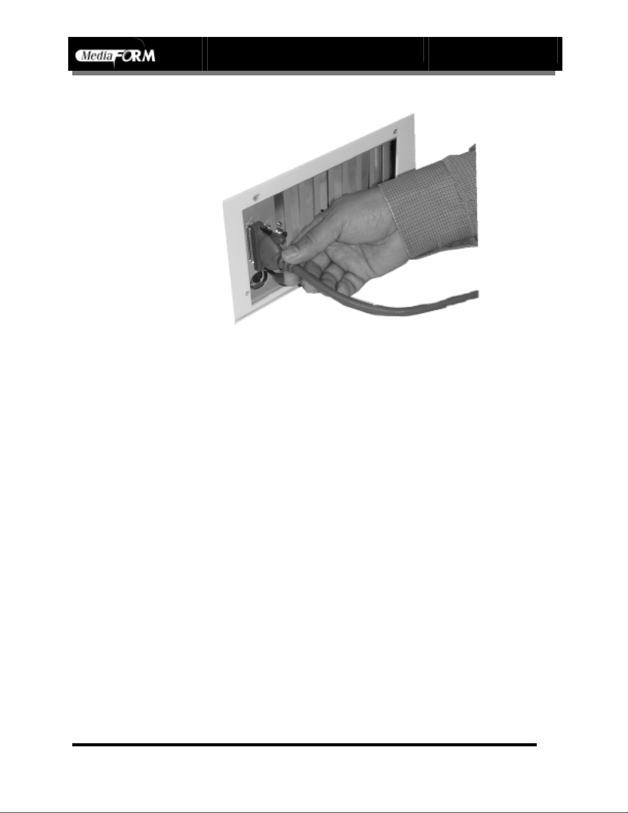
Attaching a Monitor
Place the monitor on either side of the AP-1301. Connect the male DB-15
(15-pin) connector of the monitor cable to the female DB15 connector on
the AP-1301 base unit. Connect the monitor’s power cable to the AC wall
jack. Reference the documentation that accompanied the monitor if you
need help
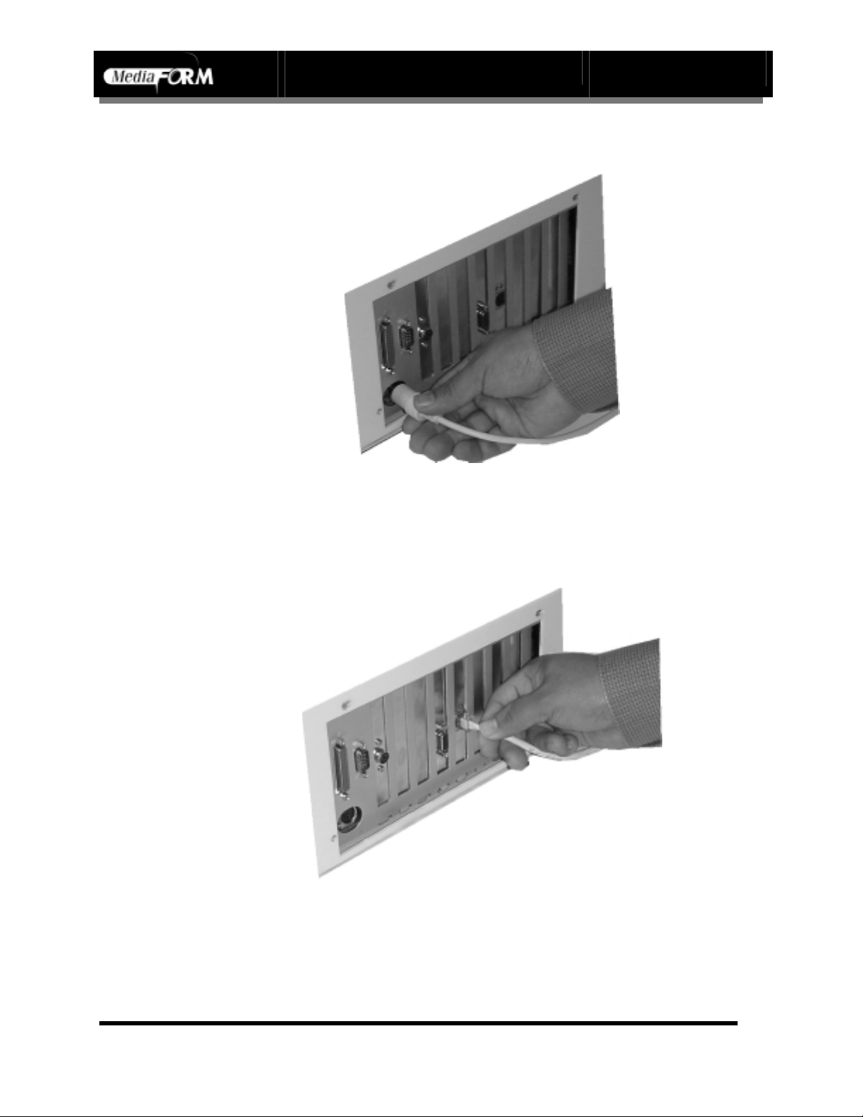
Attaching the Mouse
Either a Microsoft compatible serial or P/S2 mouse may be used. For a
serial mouse, use the DB-9 male connector located on the back of the AP1301 base unit. For a P/S2 mouse, use the mini DIN connector located on
the back of the AP-1301 base unit.
Page 7
Page 9
AP-1301 i/t Operator’s Guide
Document Revision: 100102
Attaching the Keyboard
Connect the keyboard to the large DIN located on the back of the AP-1301
base unit.
Attaching the Network Cable
If you wish to connect the AP-1301 to your network, connect a suitable
patch cord to the RJ-45 network port on the back of the AP-1301 base unit.
Use a category 3 or better patch cable for 10Base-T and category 5 for
100Base-TX.
Page 8
Page 10
AP-1301 i/t Operator’s Guide
Document Revision: 100102
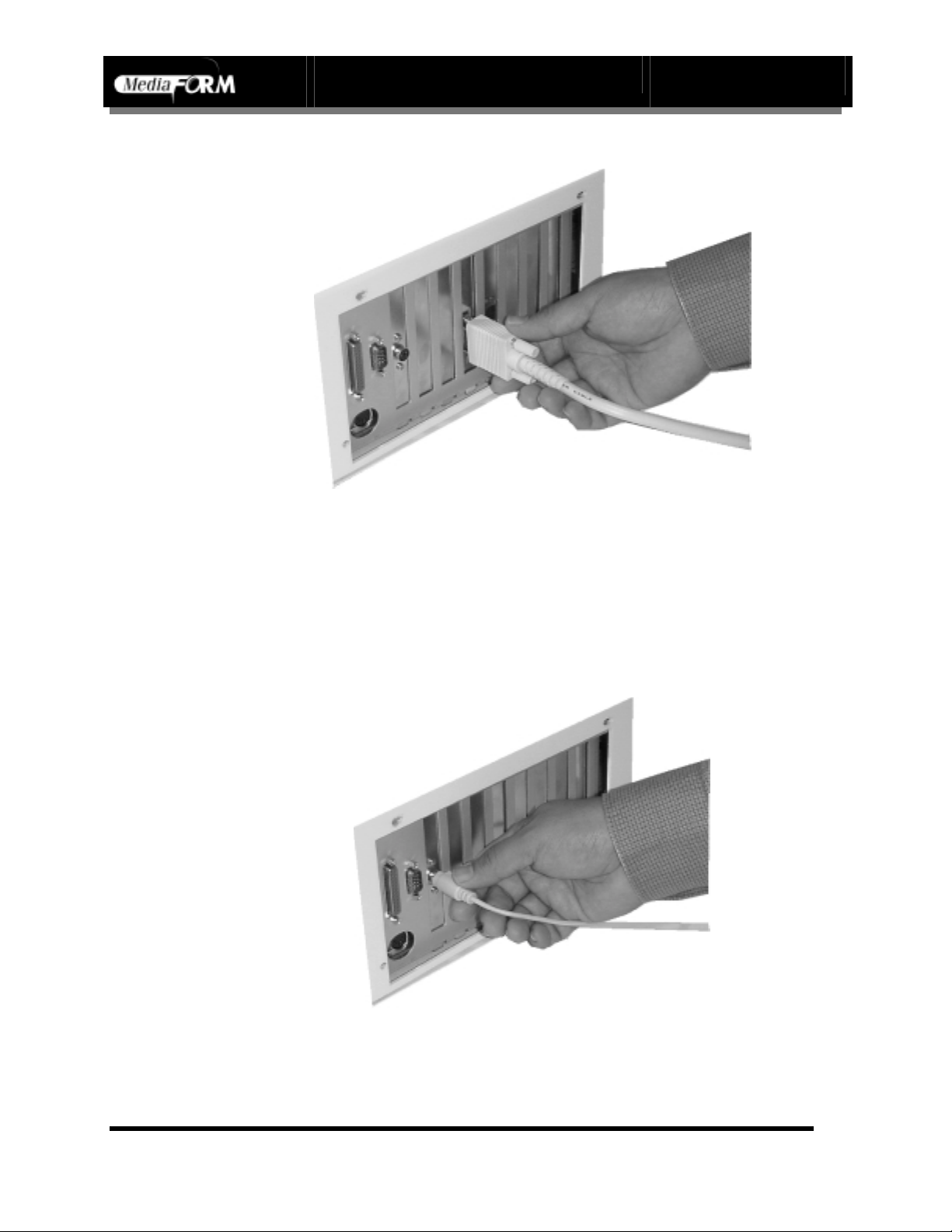
Attaching the Printer Cable
Connect the printer cable included with your printer to the female DB-25
connector on the back of the AP-1301 base unit. Connect the other end to
the port on the back of the printer. Use only IEEE-1284 compatible printer
cables.
With you printer placed on the deck of the Ap-1301, attach the printer and
power cables.
Page 9
Page 11

AP-1301 i/t Operator’s Guide
The Best Place To Put Your System
The best place for your unit is in a climate-controlled area, free of dirt, dust,
humidity, excessive heat, and electronic or electromagnetic interference. As
your AP-1301 is network ready, you may want to locate it near a network
jack. Place the AP-1301 i/t on a firm and steady work surface, allowing
sufficient room for all of your work materials. Also, allow at least six
inches of clearance around the unit for ventilation.
Safety Precautions
Your system shipped with a three-prong power connector, and is intended
for use with properly grounded AC receptacles only. Do NOT try to defeat
the third “ground” prong. All computer peripherals should be properly
grounded, and the AP-1301 is no different. The use of a power conditioner,
such as a UPS (Uninterruptable Power Supply) or a surge protector, is
always recommended with sensitive computer equipment. If you are
considering using such a device, the minimum system recommended is
400VA.
Document Revision: 100102
Repairs should only be attempted by authorized, factory-trained
technicians. MediaFORM reserves the right to void the warranty if
unauthorized service is performed.
Page 10
Page 12

AP-1301 i/t Operator’s Guide
Orientation to the Different Parts - AP-1301i
Front View
Document Revision: 100102
Rear View
Page 11
Page 13

(front bracket)
AP-1301 i/t Operator’s Guide
Orientation to the Different Parts – AP-1301t
Front View
Document Revision: 100102
Rear View
(rear bracket)
Page 12
Page 14

AP-1301 i/t Operator’s Guide
Document Revision: 100102
Removing Packing Restraints
The AP-1301 ships with a picker mechanism restraint, to ensure that the unit is not
damaged in transit. This restraint must be removed before operation or power-on. If you
have not already done so, remove the restraint before turning the unit on. Save the styrene
restraint, in the event that you need to transport the unit.
Input and Output Spindles
The spindles serve as the containers to store the blank and
printed CD-R’s. They must be installed before operation of
the unit. Let’s do so now.
First, locate the three spindles provided with your system.
Inside the original shipping carton was a smaller carton,
called the accessory box. It is in this box that you will find
the input and out spindles, along with the power cord
needed to operate the unit.
Assembling The Spindles
Assemble each spindle by screwing the metal spindle spike into the top of the plastic
spindle base. Turn the spindle clockwise until snug. Be sure you thread properly to
ensure that each spindle is fully upright.
Installing The Spindles
Position the AP-1301 unit so that the front
panel is facing you. Locate the metal
spindle guide pins marked “Spindle 1”,
“Spindle 2”, and “Spindle 3”. These pins
are found on the top deck of the unit,
behind the picker arm column, to the left
and right side.
In the bottom center of each spindle base
is a hole. Align the hole with the three
guide pins found on the deck of the AP1301 unit. Place the spindle on top of the
guide pin, so that the spindle stands
vertically. Repeat the procedure until all
three spindles are installed.
Page 13
Page 15

AP-1301 i/t Operator’s Guide
Document Revision: 100102
Spindle Designations
The AP-1301 uses three spindles. Spindle 1 is dual purpose, and is used for both input
and output. Spindle 2 is for output only. Spindle 3, like spindle 1, is also dual purpose
and is used for both input and output.
To start, place the desired number of discs to be printed on spindle 1. If you wish to
do a quantity greater than one spindle allows, place the remainder on spindle 3. The
processing of discs begins with the blanks being drawn from spindle 1, and the
printed out being placed on spindle 2. Once spindle 1 runs empty, discs will then be
drawn from spindle 3. The outputted product will then be placed on spindle 1. In the
end, all completed discs will be on the front most spindles.
Page 14
Page 16

System Startup
Locate the switch on your SVGA monitor and turn it to the on position.
Next, locate the printer power switch (refer to separate printer
documentation if you need help).
Next, we must verify that the voltage selector switch is set correctly on
each module; it is located between the two power receptacles. The AP-1301
supports both 115 VAC and 230 VAC at 50 ~ 60 Hz. Please confirm that
the appropriate voltage (115 VAC for North America) has been selected.
AP-1301 i/t Operator’s Guide
Document Revision: 100102
CAUTION
CAUTION
CAUTIONCAUTION
Always use properly grounded receptacles, or severe damage
to your system may occur. The use of a surge protector or UPS
(Uninterruptable Power Supply) is always recommended with
sensitive computer products.
Page 15
Page 17

AP-1301 i/t Operator’s Guide
Document Revision: 100102
• Now that you have confirmed the proper voltage setting, it is time to
turn the unit on.
• Make sure you power on the unit using the switch seen below, which is
located on the back of the AP 1301.
• The AP-1301 is Windows NT based and may take a couple of minutes
to start up. Upon a successful startup, you will be greeted by the
Windows NT Logon screen. When prompted, press CTRL-ALTDELETE and enter:
U
ser Name: mediaform
Password: mediaform
When logging on to Windows NT, the password is case sensitive.
• Once you logon, you will be greeted by the Windows NT desktop. For
those of you familiar with Windows 95 or Windows 98, you will find it
to be virtually the same user interface.
Note: You may want to consider supplementing this
manual with a Windows NT 4.0 Workstation
guide, many of which are readily available at
local book stores
Aligning the Printer
Before you can begin automated printing, you may need to align the printer.
Printer alignment consists of running an alignment program, and adjusting
the printer’s position by moving the brackets, which hold it in place.
Alignment is complete when the discs are placed perfectly centered in the
printer’s tray.
The brackets have been preset at the factory. Due to slight variations in
printers, and the surface on which the AP-1301 is ultimately set, the
brackets may need adjustment to “fine- tune” the printers position. Before
making any changes, the Printer Alignment Utility appearing on the
Windows NT desktop should be run.
Page 16
Page 18

AP-1301 i/t Operator’s Guide
Document Revision: 100102
Be sure to close all applications, especially the CD-3703
application itself, as it will conflict with the Printer
Alignment Utility. Locate the “Printer Alignment” ICON
Printer
Alignmen
t Utility
depicted to the left, on the desktop. Double-click on it to
launch the Printer Alignment Utility. The splash screen
below will be displayed.
• Place a disc on the input spindle. This is the spindle at the right front
side of the unit. Click on P
erform Test. You will be prompted:
Page 17
Page 19

AP-1301 i/t Operator’s Guide
Document Revision: 100102
• Follow the on-screen instruction and then click on Yes. If you click on
N
o, the process will be aborted. You will be asked:
• Once the printer’s tray is fully extended, click on Y
es to continue or No
to abort the process.
• Check the positioning of the disc in the tray. If not perfectly centered,
adjust the printer’s position by loosening the screws that hold the
brackets in place, and then adjust the printer in the appropriate direction.
Click on OK and run this test again until the disc is placed centered in
the tray. When you are happy with the results, push the brackets up
against the printer to hold it in place, and then tighten them down.
You should not have to perform this procedure again unless you relocate
the system.
• Click on Ex
it to quit the program. You will be prompted to restart the
system. To do so, click the START button on the taskbar. You will then
click SHUTDOWN. When asked, select RESTART.
Page 18
Page 20

AP-1301 i/t Operator’s Guide
Document Revision: 100102
Startup the AP-1301 Software
When the system restarts, logon as you did before. After logging on, click
the AP-1301 ICON to bring up the main AP-1301 application. The Job tab
will be displayed:
Page 19
Page 21

AP-1301 i/t Operator’s Guide
Document Revision: 100102
Operation
If you have not already done so, be sure that you have read the section entitled “Getting
Started”. This section walks you through the preliminary setup of the unit, which must be
accomplished prior to operation.
The AP-1301 is broken up into three tabs. The Status Tab, the Job Tab, and the Label
Designer Tab. The Status Tab shows what print job is running, what is queued to run, and
what has been completed.
Before a print job can be submitted, the CD design must be produced. This can be done
in two basic ways. The primary way is to use the Label Designer tab of the AP-1301
application itself. We will detail this process in a moment. The other way is through a
graphic design software package that enables you to design your own template. From
there, rather than print to the printer itself, you simply change the print driver setting to
“Print to File”. This will generate a file with a .PRN extension, which can then be used as
the “Label File” when submitting a job.
Page 20
Page 22

AP-1301 i/t Operator’s Guide
Document Revision: 100102
The Label Designer Tab
To start designing your CD, click on the Label Designer tab. Here is where we have the
ability to customize your CD’s appearance with text and graphic images. The Label
Designer tab supports a variety of graphic image formats, as well as any installed
Windows True Type font.
The Label Designer tab is dominated by two concentric circles, which graphically
represent the appearance of the CD you are designing. Horizontally along the top left side
of the tab is the menu bar. Vertically at the bottom left, is the toolbar.
Page 21
Page 23

AP-1301 i/t Operator’s Guide
The Label Designer Menu Bar
As we look at the AP-1301’s Label Designer, we see the top horizontal
toolbar, containing New, Open, Save, Delete, and Help (Please take note
that HELP was not implemented for this revision)
The menu button functions are as follows:
Clicking on the new button will clear the screen, and allow you to
start on a new label design.
Allows you to open an existing label file (*.LBL).
Allows you to save the label currently displayed
Allows you to delete an object currently selected with the pick
tool, described in the “toolbar” section.
Not currently implemented
Document Revision: 100102
.
The Tool Bar
At the bottom left of your screen, you will find a vertical
toolbar. The toolbar consists of five buttons or tools. These are
the: Point / Select Tool, Type Text Tool, Im port Bitmap Tool,
Select Font Tool, and the Add Date Tool.
The menu buttons functions are as follows:
Select this tool by clicking on it. Once selected, it can be used to
reposition text or graphic images. You may also use it to select
items to be deleted, by using the DELETE button on the Menu
Bar
Page 22
Page 24

AP-1301 i/t Operator’s Guide
Used to add text to the label being designed. Select this tool, and
click on the location where the text should appear. Use the
“Point” tool to reposition it, or double click on the text created to
Document Revision: 100102
modify it. To change fonts or colors, you must first use the
“Select Font” tool, and then the “Type Text” tool.
Allows you to import a graphic image file. It is best to use
images optimized for the current printer. With the MediaFORM
Spectrum, 300 DPI pictures of no more than 4.5” work best. For
the Primera, 600 DPI (or 1200, but little improvement will be
seen) pictures of no more than 4.5” square.
Select this tool to choose the desired font or color, before
selecting the “Type Text” tool
Allows you to add a dynamic date field that will reflect the
current date when printed
Using “Type Text” Tool
The text tool allows you to create a text element for your CD. It can be
repositioned, or it’s font attribute changed, by using the Point tool below.
To use this tool:
• Select Type Text tool by clicking
on that button
• Move the cursor (mouse) to the
image of the CD, and click once
• Enter the text you wish to display.
For our example, we will type
“Label Designer”
Using “Point” Tool
The point tool is used to select the different elements that make up your
CD’s design. This tool is the one used when you wish to reposition an
element or change its attributes such as size, font, or location.
To change fonts in a text element:
• Select Point by clicking on that button
• Click on the text or graphic, and hold down the mouse. You will then
maneuver the object to it’s appropriate location. You may resize graphic
Page 23
Page 25

AP-1301 i/t Operator’s Guide
Document Revision: 100102
images by clicking on one of the corner handles of the graphic, and
dragging it to increase or decrease its size.
• To change the attributes of a text element, simply double-click on it. To
change the text fill in the box, or to change the font, click on the Select
Font button displayed.
Note: To change FONT color, you must first select the font, type
size, and color, using the Select Font option
Using “Import Bitmap” Tool
The Import Bitmap tool allows you to import a graphic image from a file.
To use the Import Bitmap tool:
• Select Import Bitmap by clicking on that button
• Choose the graphics file you desire from any available BMP, JPG, TIF,
or any of the other various supported formats.
• Click Open to display your selection
• Click on Point to place it in position
• Click on the border (see image) and you may enlarge or shrink the
image
• Select Save, and you will save the file as an “LBL”(Label”) f ile. If you
wanted to name it Test, the file will be called Test.lbl
Congratulations, you have just designed your first CD!
Page 24
Page 26

AP-1301 i/t Operator’s Guide
Document Revision: 100102
The Job Tab
Once you have designed your CD, the Job Tab is your next stop. It is through this tab of
the AP-1301 application that all print jobs are submitted. A print job can be thought of
simply as a work order. This work order defines how many discs are to be produced, and
which artwork is to be used. New jobs are created here. In addition, you may recall and
use previously saved jobs. In this way, job files of frequently produced discs can be
created once, and then reused many times.
The Job Menu Bar
Looking at the AP-1301’s Job tab, you will see the top horizontal toolbar
containing: New, Open, Save, About, and Help (Please take note that
HELP was not implemented for this revision)
.
Page 25
Page 27

AP-1301 i/t Operator’s Guide
Document Revision: 100102
The Job Tab menu button functions are as follows:
Clicking on the new button will clear the screen and allow you to
create a new job.
Allows you to open an existing job file (*.job).
Allows you to save the job currently displayed for future use.
Displays the version information of the AP-1301 application
currently running.
Not currently implemented
Creating a print Job
In order to start printing, you must first create a print job. Fill in the fields as described
below:
JOB ID
• This field can contain up to 20 user-defined characters. While the
contents of this field are up to you, it is a mandatory field and cannot be
left blank. You may want to consider a date code, product number,
invoice number, or work order number. The number entered here will be
displayed while the job is running and may prove to be a useful
reference.
GENERAL OPTIONS
PRINT
• Print should always be left selected. If disabled,
the unit will not print. This checkbox is for
service use only.
ALIGN
• “Align” may be used with units that have the
MediaFORM USA’s SmartAlign optical disc
alignment option installed. This option allows
Page 26
Page 28

LABEL FILE
AP-1301 i/t Operator’s Guide
Document Revision: 100102
you to print relative to the artwork on a pre-silk screened disc. In other
words, you can have your CD-Rs silk screened with generic artwork,
and then customize them by printing in an area left for the title. The
SmartAlign feature will rotate the disc before printing, so that the
overprint is in the area left for the title or unique information.
The “Label File” field displays the desired label file to be used for printing.
Only “.LBL” and “.PRN” are used.
Note: PRN files are created when the printer properties port setting is set to
PRINT-TO-FILE. This allows other applications to create printable files.
These files must be created with the appropriate printer, either the
Primera or the MediaFORM Spectrum, set as the default printer. These
files are essentially captured printer dump files. PRN files, once created,
are not editable. It is also important to note that they contain all printer
settings. In the event of a problem when using a PRN file as the source,
check your printer’s settings in START-SETTINGS-PRITNERS, and then
regenerate the PRN file. These setting will be saved within the PRN file
and will over-ride any current printer settings.
To select the desired label file, the steps are as follows:
• Click on Browse Print Files. The following dialog box will be
displayed:
Page 27
Page 29

AP-1301 i/t Operator’s Guide
Document Revision: 100102
• By default, the LABELS folder will open. Click on and highlight the
desired file you are selecting.
• Click on the “open” button, and the highlighted label file will be
selected.
QUANTITY
• Enter the desired number of discs to print, of the selected label file.
COMMENTS
• This is an optional field. Any comments, such as job description, may
be entered here.
Open, save and submit job
Page 28
Page 30

AP-1301 i/t Operator’s Guide
Document Revision: 100102
The above three buttons will also be found on the Job Tab. “Open” and
“Save” have the same functionality as the buttons on the horizontal tool
bar, appearing at the top left of the Job Tab. The buttons function as
follows:
Open Job
• Performs the same task as Open does in the top horizontal toolbar.
• Allows you to open an existing job file.
Save As
• Saves the JOB file as it appears on your screen.
• Performs the same task as Save does in the top horizontal toolbar
Submit
• Starts the displayed JOB.
Page 29
Page 31

AP-1301 i/t Operator’s Guide
Document Revision: 100102
Status Screen
The Status Tab allows you to monitor the progress of jobs. As you view the Status tab,
you will notice 3 panes. Each of these panes shows the different “states” of a job. The top
pane shows you which jobs are pending, the second pane shows which job is running,
and the third and bottom most pane shows which jobs have been completed or have
failed.
Job Queue
Within Job Queue, there are 3 fields and 2 buttons:
Job ID
• The Job ID is the name that was given to the job when it was created.
Note: It can be a good idea to give each job a unique ID. We recommend
using something such as work order number, an invoice number, or a
date code.
Page 30
Page 32

Total
• This field shows the total number of CDs that are requested, per job.
Requested
• This field displays the time the job was submitted to the CD-3703
Eclipse
Job Queue Screen
Here you see how a job appears when it is in the Job Queue pane:
Note: In this example, you see a job waiting to be processed. For the Job
In addition to the 3 features mentioned, you see the Start New Job and
Remove Job buttons.
Start New Job:
• Allows you to start a new job. Upon clicking here, you will be returned
to the Job Tab. Any jobs currently being processed will continue to run.
Remove Job
• This allows you to remove a job from the queue. This has no effect on
the job file itself. It simply deletes it is as a pending job. The job file
may be opened, or submitted at a later time.
AP-1301 i/t Operator’s Guide
Document Revision: 100102
ID, we named it, “This next job is yours”! To reiterate what was
mentioned earlier in the Job Screen; we recommend that you give
each job a set of unique identifying numbers, letters, or a
combination of both.
Page 31
Page 33

Running Jobs
Within the
JobID
• This is the JOBID of the active job.
Total
• Represents the desired number of discs to print.
Good
• Represents the number of discs successfully completed.
Bad
• Represents the number of discs that have failed to print correctly. If this
Started
• Represents the time your job was submitted.
Status
• The Status field shows you what is happening to your job as it is being
AP-1301 i/t Operator’s Guide
Document Revision: 100102
Running Jobs pane, there are 6 fields:
number is high, you may need to readjust the alignment of the printer on
the deck of the AP-1301.
processed. This will typically read printing, or loading.
Completed Jobs
Within Completed Jobs there are many of the same fields discussed earlier
in this section. The Completed field is the only new field. This field
displays the time at which the job was completed.
Page 32
 Loading...