

Page 1
VX-1
Stereo
Program
Equalizer
Operating Instructions
The Meyer Sound VX-1 is a two-channel program equal-
izer featuring three bands of minimum-phase boost or
cut equalization per channel. Optimized for composite
response shaping of stereo program material, the VX-1
utilizes a unique Virtual Crossover™ implementation,
with two frequency breakpoint controls and separate
gain controls for the Low, Mid and High bands.
Meyer Sound Laboratories, Inc.
2832 San Pablo Avenue
Berkeley, CA 94702
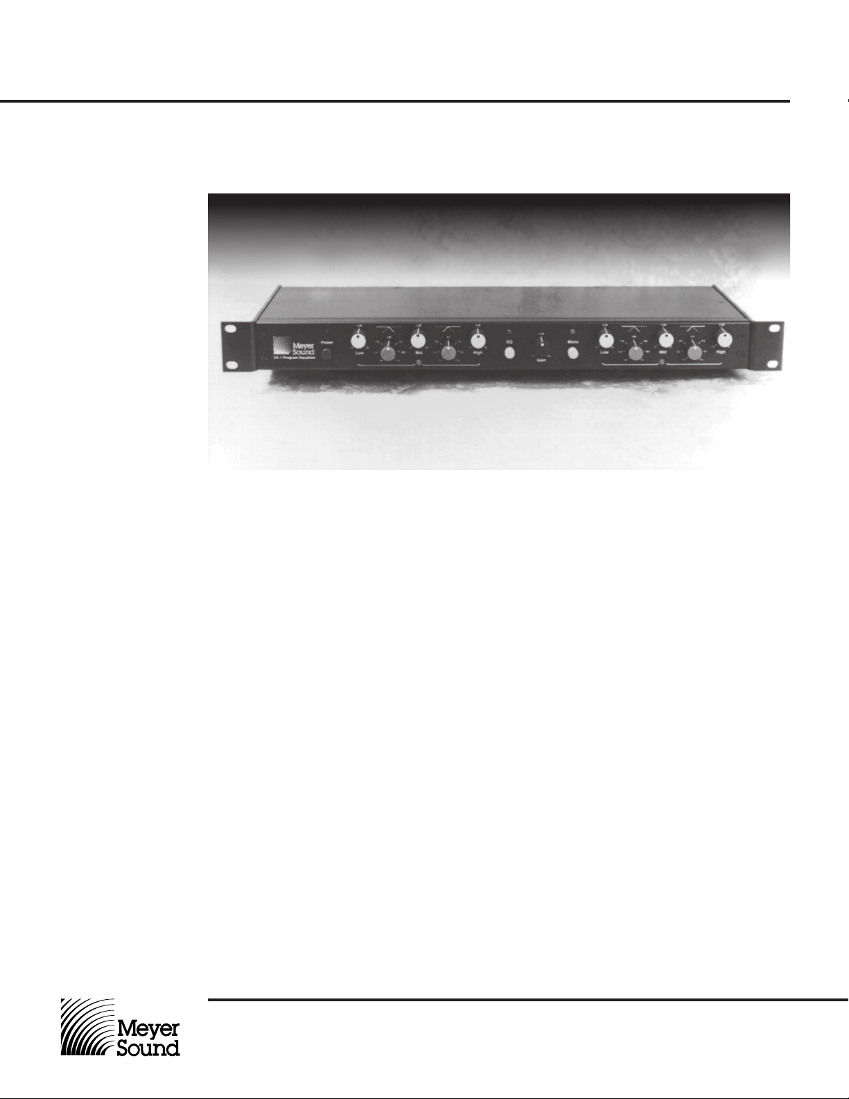
The VX-1 occupies a single 1.75" standard rack
space, and the clearly marked controls include a
Master gain control, a single EQ In/Out switch and
a convenient Mono switch. Single-pole, minimum-
phase circuitry assures natural, graceful sonic
characteristics, even at extreme settings. The
dynamic range of the VX-1 exceeds 100 dB.
Page 2

VX-1
PUSH PUSH
Stereo
Program
Equalizer
Operating Instructions
Input Connections The VX-1 accommodates nominal input levels of +4 dBu
(XLR connectors) balanced, or -10 dBV (RCA connectors)
unbalanced, selected by a rear-panel recessed switch.
The +4 dBu XLR input circuitry employs Meyer Sound’s
exclusive ISO™ Input, affording exceptional immunity from
ground loops and common-mode noise. The circuit makes
use of custom transformers employing a high-inductance
Source Output
Configuration
Balanced n/c - +
Unbalanced n/c GND +
Wiring of ISO™ Input
Pin 1 Pin 2 Pin 3
n/c + -
n/c + GND
Figure 1. ISO™ Input Polarity Table
VX-1 Output Polarity
Pin 1 Pin 2 Pin 3
GND - +
GND + -
GND - +
GND + -
nickel core and Faraday shield, achieving 500 volts of common-mode isolation. All three input connector pins float from
both circuit ground and chassis ground.
The ISO™ input circuit accommodates a wide variety of
input wiring configurations with no change in gain. Figure 1
illustrates output polarity for various balanced and unbalanced connections.
Output Connections Signal outputs from the VX-1 are active balanced, at nominal
+4 dBu operating level. The connectors may be wired bal-
AC Power Inlet and
Voltage Selector
The VX-1 is equipped with an international standard IEC 320
Mains AC inlet that accepts a variety of power cord types to
Connect -10 dBV unbalanced signal sources to the
rear-panel RCA connectors. These inputs bypass the
ISO™ transformer stage, and the connector shells are
tied to circuit ground.
Upon making input connections, check to be sure that
the input selector switch is set correctly.
anced or unbalanced, with maximum output levels
before clipping of +25 dBu or +19 dBu, respectively.
Meyer Sound, or an equivalent that satisfies the
requirements of the local safety testing agency.
accommodate mains outlets worldwide.
To change the AC voltage setting, first disconnect
The VX-1 must have the correct power cord, voltage setting
and fuse for the AC power source in your area. To avoid
electrical shock and damage, use only the cord specified by
AC Fuse To replace the fuse, insert a flat-blade screwdriver in
Primary protection for the VX-1 is provided by a
1
¦4 A SloBlo
fuse located in a receptacle adjacent to the AC inlet. Before
examining or replacing the fuse, first disconnect the AC
cord.
the AC cord. Using a small flat-blade screwdriver,
move the slide switches to the appropriate position as
indicated by the adjacent panel legend.
the fuse cap and gently turn counterclockwise. The
fuse will spring from its socket. Replace only with a
fuse of the type and rating specified by Meyer Sound.
Input
Select
XLR
RCA
+4 dBu
+4 dBu
Balanced
Input
-10 dBV
Input A
+4 dBu
-10 dBV
Unbalanced
Input
Meyer Sound Laboratories, Inc.
2832 San Pablo Avenue
Berkeley, CA 94702
CAUTION:
AC Voltage Ranges
-10 dBV
Input B
Output A Output B
210 - 250
170 - 210
105 - 125
85 - 105
+4 dBu
Balanced
Output
Figure 2. VX-1 Rear Panel Connections (one channel shown)
Set voltage before applying power.
85-105
105-125
210-250
170-210
AC Voltage
1
A
/
4
Slo Blo
85-250V
50-60Hz
20W MAX
Mains
AC Power
Cord
Page 3

VX-1
Stereo
Program
Equalizer
Operating Instructions
0 dB
-3
4 k
6 k
17 k
+3
-6
+6
-12
9 k
0 dB
+2
-3
+3
-6
-12
-24
+6
-
∞
Gain
VX-1 Program Equalizer
0 dB
-3
+3
-6
Power EQ Mono
-12
Low Mid High
240
175
+6
110
60
0 dB
-3
+3
-6
320
490
1 k
-12
Channel A
3 k
+6
2 k
1 k
Figure 3. VX-1 Front Panel Controls
EQ In/Out Switch The EQ In/Out Switch engages (in) or bypasses (out) the
VX-1 equalization stages. When the equalization is engaged,
the LED lights and the equalization controls are active.
Master Gain Control The Master Gain Control regulates the gain of the VX-1. Its
range is from off to +6 dB, with 0 dB (unity) gain at the center
position.
Mono Switch When the Mono Switch is engaged (in), the LED lights and
the two input channels are summed and routed to both out-
Signal/Clip Indicators Centered directly under the equalization controls for each
channel, the Signal/Clip indicators will flicker green when
Equalization Controls The VX-1 features a unique, Virtual Crossover™ implemen-
tation which is well suited for tailoring the broadband response of program material. Operationally, it may be likened
to a conventional active loudspeaker crossover.
Each channel of equalization incorporates five controls: two
frequency breakpoint controls, and three band gain controls.
The left-hand frequency control regulates the frequency
breakpoint between the Low and Mid bands, while the righthand frequency control regulates the breakpoint between the
0 dB
-3
+3
+4
+5
-6
-12
Low Mid High
240
175
+6
110
60
0 dB
-3
+3
4 k
-6
320
490
1 k
-12
Channel B
3 k
+6
2 k
-6
6 k
9 k
17 k
1 k
When the equalization is bypassed, only the Master
Gain control and Mono switch are active.
puts with equal amplitude. When the Mono switch is
disengaged (out), the VX-1 operates in stereo.
their corresponding channels are passing audio. The
indicators flash red to register signal clipping.
Mid and High bands. The gain controls affect the
relative amplitude (boost or cut) within each frequency
band, with a range of -12 to +6 dB.
The VX-1 equalization sections are first-order (6 dB/
octave) minimum-phase networks that provide gentle,
natural sonic characteristics. Figure 4 illustrates
typical response curves for various midrange control
settings.
0 dB
-3
+3
+6
-12
+6.0
+3.0
0.0
Gain in dB
-3.0
-6.0
-9.0
-12.0
Meyer Sound Laboratories, Inc.
2832 San Pablo Avenue
Berkeley, CA 94702
20 100 1k 10k 20k
Frequency in Hz
Figure 4. VX-1 Response at Various Midrange Settings
Page 4

VX-1
Stereo
Program
Equalizer
Operating Instructions
Specifications
Frequency Response
1
Equalization In (Controls set flat)
Equalization Bypassed
Total Harmonic Distortion
Hum and Noise
Dynamic Range
3
4
2
Inputs
XLR
Type
Impedance
Nominal Input Level
Maximum Input Level
7
RCA
Type
Impedance
Nominal Input Level
Maximum Input Level
Outputs
Type
Impedance
Nominal Output Level
Maximum Output Level
20 – 20,000 Hz +0, -0.5 dB
20 – 20,000 Hz +0, -0.5 dB
< .005%
< – 90 dBV “A” Weighted
> 100 dB
Balanced, transformer-isolated ISO™ Input
16k ohms, 8k ohms per branch unbalanced
5
6
+4 dBu, 16 dB headroom
+20 dBu
Unbalanced active
8k ohms
-10 dBV
0 dBV
Balanced active push-pull, pin 1 to chassis = 500ý
300 ohms, 150 ohms per branch unbalanced
+4 dBu
+25 dBu
Notes:
1. Measured at 0 dB gain
2. +18 dBV input, 1 kHz
3. Unbalanced
4. “A” weighted noise floor
to maximum RMS
output
5. ISO™ input: Pins 1, 2
and 3 are transformerisolated. Shell is
connected to chassis/
AC mains ground. Pin
3 positive for positivegoing output at pin 3.
6. Pure resistive throughout audio band
7. Within operating band
of each channel, this is
the minimum worstcase level achieved
before clipping.
8. 0 dBu ³ 0.775 vrms
0 dBV = 1 vrms
Controls & Indicators
Front Panel
Power
EQ In/Out
Mono/Stereo
Frequency, Gain
Master
Rear Panel
+4 dBu/-10 dBV select switch
Connectors
Balanced Input, Output
Unbalanced Input
Power
Physical
Dimensions
Weight
© 1991, Meyer Sound. 05.045.010.01 A
Locking pushbutton, red LED
Locking pushbutton, green LED
Locking pushbutton, yellow LED
31-position detented rotary controls
Rotary control
Recessed toggle
3-pin XLR male, female
Gold-plated RCA female
100/120/220/240 VAC, 50/60 Hz (switchable), 20W
19" W x 1.75" H x 7.5" D standard rack mount
8 1/4 lbs (3.75 kg)
Meyer Sound Laboratories, Inc.
2832 San Pablo Avenue
Berkeley, CA 94702
Page 5

VX-1
Stereo
Program
Equalizer
Operating Instructions
Examples of Program
Equalization
The examples on this page illustrate typical response
characteristics obtained with various settings of the VX-1
band gain and frequency controls.
0
-4-8 +8+4
Gain in dB
50 Hz 20 kHz
Frequency
0 dB
-3
+3
-6
175
+6
-12
Low Mid High
110
60
0 dB
-3
490
-6
-12
Channel A
+3
3 k
+6
2 k
240
320
1 k
The control settings (Channel A only) used to obtain a
specific response are shown in the detail below the curve
plot.
0 dB
-3
4 k
17 k
1 k
+3
-6
6 k
-12
9 k
EQ
+6
0 dB
+2
-3
+3
-6
-12
+4
+5
-24
+6
-
∞
Gain
Symmetrical High- and Low-Frequency Boost
0
-4-8 +8+4
Gain in dB
50 Hz 20 kHz
Frequency
0 dB
-3
+3
-6
175
+6
-12
Low Mid High
110
60
0 dB
-3
240
1 k
+3
-6
320
490
-12
Channel A
3 k
+6
2 k
1 k
Symmetrical High- and Low-Frequency Cut
0 dB
-3
4 k
6 k
17 k
+3
-6
-12
9 k
EQ
+6
0 dB
+2
-3
+3
-6
-12
+4
+5
-24
+6
-
∞
Gain
Meyer Sound Laboratories, Inc.
2832 San Pablo Avenue
Berkeley, CA 94702
Page 6

VX-1
Stereo
Program
Equalizer
Operating Instructions
0
-4-8 +8+4
Gain in dB
50 Hz 20 kHz
Frequency
0 dB
-3
+3
-6
175
+6
-12
Low Mid High
110
60
0 dB
-3
240
1 k
+3
-6
320
490
-12
Channel A
3 k
+6
2 k
1 k
0 dB
-3
4 k
17 k
+3
-6
6 k
-12
9 k
EQ
+6
0 dB
+2
-3
+3
-6
-12
+4
+5
-24
+6
-
∞
Gain
Gradual Downward Tilt
0
-4-8 +8+4
Gain in dB
50 Hz 20 kHz
Frequency
0 dB
-3
+3
-6
175
+6
-12
Low Mid High
110
60
0 dB
-3
240
1 k
+3
-6
320
490
-12
Channel A
3 k
+6
2 k
1 k
0 dB
-3
4 k
17 k
+3
-6
6 k
-12
9 k
EQ
+6
0 dB
+2
-3
+3
-6
-12
+4
+5
-24
+6
-
∞
Gain
Meyer Sound Laboratories, Inc.
2832 San Pablo Avenue
Berkeley, CA 94702
Gradual Upward Tilt
 Loading...