

Page 1
OPERATING INSTRUCTIONS
UPQ-D1 Wide Coverage Loudspeaker
UPQ-D2 Narrow Coverage Loudspeaker
UPQ-D3 Wide Symmetrical Coverage Loudspeaker
ULTRA
Keep these important operating instructions.
Check www.meyersound.com for updates.
Page 2

© 2019
Meyer Sound. All rights reserved.
UPQ-D1/D2/D3 Operating Instructions, PN 05.291.005.01 A
The contents of this manual are furnished for informational purposes only, are subject to change without notice, and should not be
construed as a commitment by Meyer Sound Laboratories Inc. Meyer Sound assumes no responsibility or liability for any errors or
inaccuracies that may appear in this manual. Except as permitted by applicable copyright law, no part of this publication may be
reproduced, stored in a retrieval system, or transmitted, in any form or by any means, electronic, mechanical, recording or otherwise,
without prior written permission from Meyer Sound.
CAL, Compass Go by Meyer Sound, Compass RMS, Intelligent AC, LEO-M, LEOPARD, LYON, MAPP, RMS, UltraSeries, and all alphanumeric designations for Meyer Sound products and accessories are trademarks of Meyer Sound. Meyer Sound, Compass, Constellation,
Galileo, LEO, QuickFly, SIM, Spacemap, Thinking Sound, TruPower, Tru Sh ap in g, a nd U -S ha pi ng , ar e re gi st ered t rad em ark s of M eye r
Sound Laboratories Inc. (Reg. U.S. Pat. & Tm. Off.). All third-party trademarks mentioned herein are the property of their respective
trademark holders.
ii
Page 3
UPQ-D SERIES OPERATING INSTRUCTIONS
!
!
IMPORTANT SAFETY INSTRUCTIONS
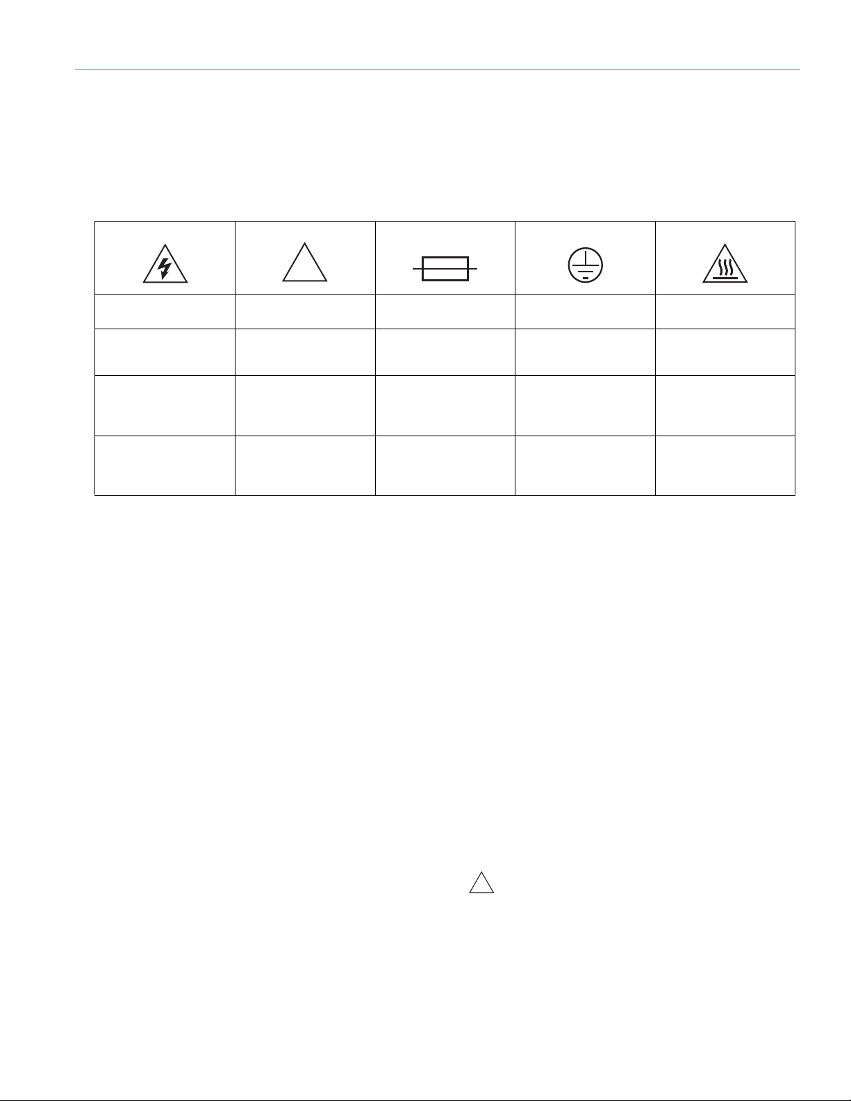
These symbols indicate important safety or operating features in this booklet and on the frame or chassis:
SYMBOLS USED
Dangerous voltages:
risk of electric shock
Gefährliche
Spannungen:
Stromschlaggefahr
Pour indiquer les
risques
résultant de tensions
dangereuses
Para indicar voltajes
peligrosos
Important operating
instructions
Hinweis auf wichtige
Punkte der
Betriebsanleitung
Instructions d'utilisation
importantes
Instrucciones
importantes
de funcionamiento y/o
Mantenimiento
Replaceable Fuse Protective earth ground Hot surface: do not
Austauschbare
Fusible remplaçable Terre de protection Surface chaude:
Fusible reemplazable Toma de tierra de
1. Read these instructions.
2. Keep these instructions.
3. Heed all warnings.
4. Follow all instructions.
5. Do not use this apparatus near water.
6. Clean only with dry cloth.
7. Do not block any ventilation openings. Install in accordance with Meyer Sound's installation instructions.
8. Do not install near any heat sources such as radiators,
heat registers, stoves, or other apparatus that produce
heat.
9. Do not defeat the safety purpose of the grounding-type
plug. A grounding type plug has two blades and a third
grounding prong. The third prong is provided for your
safety. If the provided plug does not fit into your outlet,
consult an electrician for replacement of the obsolete
outlet.
10. Protect the power cord from being walked on or
pinched, particularly at plugs, convenience receptacles,
and the point where they exit from the apparatus. The
AC mains plug or appliance coupler shall remain readily
accessible for operation.
touch
Sicherung
Schutzerde Heiße Oberfläche:
protección
nicht berühren
ne pas toucher
Superficie caliente:
no tocar
11. Only use attachments/accessories specified by Meyer
Sound.
12. Use only with the caster rails or rigging specified by
Meyer Sound, or sold with the apparatus. Handles are
for carrying only.
13. Unplug this apparatus during lightning storms or when
unused for long periods of time.
14. If equipped with an external fuse holder, the replaceable
fuse is the only user-serviceable item. When replacing
the fuse, only use the same type and the same value.
15. Refer all other servicing to qualified service personnel.
Servicing is required when the apparatus has been damaged in any way, such as when the power-supply cord or
plug has been damaged; liquid has been spilled or
objects have fallen into the apparatus; rain or moisture
has entered the apparatus; the apparatus has been
dropped; or when for undetermined reasons the apparatus does not operate normally.
WARNING: To re d uc e t h e ri sk of f ir e o r e le ct r ic
shock, do not expose this apparatus to rain or
moisture. Do not install the apparatus in wet or humid
locations without using weather protection equipment from Meyer Sound.
iii
Page 4

IMPORTANT SAFETY INSTRUCTIONS
!
PowerCON Use
CAUTION: Disconnect the mains plug before
disconnecting the power cord from the loud-
speaker.
English
•To reduce the risk of electric shock, disconnect the
apparatus from the AC mains before installing audio
cable. Reconnect the power cord only after making all
signal connections.
•Connect the apparatus to a two-pole, three-wire grounding mains receptacle. The receptacle must be connected
to a fuse or circuit breaker. Connection to any other type
of receptacle poses a shock hazard and may violate
local electrical codes.
•Do not install the apparatus in wet or humid locations
without using weather protection equipment from Meyer
Sound.
•Do not allow water or any foreign object to get inside the
apparatus. Do not put objects containing liquid on or
near the apparatus.
•To reduce the risk of overheating the apparatus, avoid
exposing it to direct sunlight. Do not install the apparatus
near heat-emitting appliances, such as a room heater or
stove.
•If equipped with an external fuse holder, the replaceable
fuse is the only item that can be serviced by the user.
When replacing the fuse, only use the same type and
value.
•This apparatus contains potentially hazardous voltages.
Do not attempt to disassemble the apparatus. The only
user-serviceable part is the fuse if so equipped. All other
repairs should be performed only by factory-trained service personnel.
Deutsch
•Zur Minimierung der Gefahr eines elektrischen Schlages
trennen Sie das Produkt vor dem Anschluss von Audiound/oder Steuerleitungen vom Stromnetz. Das Netzkabel darf erst nach Herstellung aller Signalverbindungen
wieder eingesteckt werden.
•Das Produkt an eine vorschriftsgemäss installierte
dreipolige Netzsteckdose (Phase, Neutralleiter, Schutzleiter) anschließen. Die Steckdose muss vorschriftsgemäß mit einer Sicherung oder einem
Leitungsschutzschalter abgesichert sein. Das
Anschließen des Produkts an eine anders ausgeführte
Stromversorgung kann gegen Vorschriften verstossen
und zu Stromunfällen führen.
•Das Produkt nicht an einem Ort aufstellen, an dem es
direkter Wassereinwirkung oder übermäßig hoher Luftfeuchtigkeit ausgesetzt werden könnte, solange es sich
nicht um ein Produkt handelt, dass mit der Meyer Sound
Weather Protection Option ausgestattet ist.
•Vermeiden Sie das Eindringen von Wasser oder Fremdkörpern in das Innere des Produkts. Stellen Sie keine
Objekte, die Flüssigkeit enthalten, auf oder neben dem
Produkt ab.
•Um ein Überhitzen des Produkts zu verhindern, halten
Sie das Gerät von direkter Sonneneinstrahlung fern und
stellen Sie es nicht in der Nähe von wärmeabstrahlenden
Geräten (z.B. Heizgerät oder Herd) auf.
•Bei Ausstattung mit einem externen Sicherungshalter ist
die austauschbare Sicherung das einzige Gerät, das vom
Benutzer gewartet werden kann. Verwenden Sie beim
Austausch der Sicherung nur den gleichen Typ und
Wert.
•Dieses Gerät enthält möglicherweise gefährliche Spannungen. Versuchen Sie nicht, das Gerät zu zerlegen. Der
einzige vom Benutzer zu wartende Teil ist die Sicherung,
falls vorhanden. Alle anderen Reparaturen dürfen nur von
im Werk geschultem Servicepersonal ausgeführt
werden.
Français
•Pour éviter tout risque d’électrocution, débranchez
l’enceinte de la prise secteur avant de mettre en place le
câble audio.Ne rebranchez le cordon secteur qu’après
avoir procédé à toutes les connexions de signal audio
•Branchez l’enceinte sur une prise murale à deux fiches et
trois conducteurs avec terre. Cette prise doit être reliée à
une ligne électrique protégée par un fusible ou un courtcircuit. Utiliser une prise murale de type différent crée
des risques d’électrocution, et peut enfreindre des réglementations électriques locales.
•N’installez pas l’enceinte dans des endroits humides ou
en présence d’eau sans utiliser d’équipements de protection adéquats fournis par Meyer Sound.
•Ne laissez pas d’eau ou d’objet étranger, quel qu’il soit,
pénétrer à l’intérieur de l’enceinte. Ne posez pas d’objet
contenant du liquide sur ou à proximité de l’enceinte.
iv
Page 5

UPQ-D SERIES OPERATING INSTRUCTIONS
•Pour réduire les risques de surchauffe, évitez d’exposer
directement l’enceinte aux rayons du soleil. Ne l’installez
pas à proximité de sources de chaleur, radiateur ou four
par exemple.
•S'il est équipé d'un porte-fusible externe, le fusible remplaçable est le seul élément qui peut être réparé par
l'utilisateur. Lors du remplacement du fusible, n'utilisez
que le même type et la même valeur.
•Cet appareil contient des tensions potentiellement dangereuses. N'essayez pas de démonter l'appareil. La
seule pièce pouvant être réparée par l'utilisateur est le
fusible, s'il en est équipé.Toutes les autres réparations
doivent être effectuées uniquement par du personnel de
maintenance formé en usine.
Español
•Para reducir el riesgo de descarga eléctrica, desconecte
el aparato de la red eléctrica antes de instalar el cable de
audio. Vuelva a conectar el cable de alimentación sólo
después de realizar todas las conexiones de señal.
•Conecte el aparato a una toma de corriente de dos polos
y tres hilos con conexión a tierra. El receptáculo debe
estar conectado a un fusible o disyuntor. La conexión a
cualquier otro tipo de receptáculo representa un riesgo
de descarga eléctrica y puede violar los códigos eléctricos locales.
To da s l a s d em á s r ep a ra c io n es de b en se r re al i za d as ún i camente por personal de servicio capacitado de fábrica.
•No instale el aparato en lugares húmedos o mojados sin
usar el equipo de protección contra intemperie de Meyer
Sound.
•No permita que penetre agua u otros objetos extraños
en el interior del aparato. No coloque objetos que contengan líquido sobre o cerca de la unidad.
•Para reducir el riesgo de sobrecalentamiento del
aparato, evite exponerlo a la luz solar directa. No instale
la unidad cerca de aparatos que emitan calor, como un
calefactor o una estufa
•Si está equipado con un portafusibles externo, el fusible
reemplazable es el único elemento que puede ser reparado por el usuario. Cuando reemplace el fusible, use
solamente el mismo tipo y valor.
•Este aparato contiene voltajes potencialmente peligrosos. No intente desmontar la unidad. La única pieza que
el usuario puede reparar es el fusible si equipado con él.
v
Page 6

IMPORTANT SAFETY INSTRUCTIONS
vi
Page 7

CONTENTS
UPQ-D SERIES OPERATING INSTRUCTIONS
Important Safety Instructions iii
Symbols Used iii
Chapter 1: Introduction 9
How to Use This Manual 9
The UPQ-D Series Loudspeaker 9
Integrated Amplifier and Processing 10
Rig-Ready 10
Total System Approach 10
Chapter 2: Power Requirements 13
AC Power Distribution 13
AC Connectors 14
Wiring AC Power Cables 15
Voltage Requirements 15
Current Requirements 15
Intelligent AC Power Supply 16
Electrical Safety Guidelines 17
Chapter 3: Amplification and Audio Connectors 19
Audio Connectors 19
TruPower Limiting 20
On/Status LED 21
Amplifier Cooling System 21
Chapter 4: Adding Low Frequency Control 23
Adding Subwoofers by Daisy-Chaining 23
Using a Processor 23
Chapter 5: QuickFly Rigging 25
Important Safety Considerations! 25
Basic Eye Bolt Rigging 25
UPQ-D Series Rigging Accessories 26
Pole-Mounting the UPQ-D Series 26
The MYA-UPQ Mounting Yoke 26
The MPA-UPQ Array Adapter 27
Chapter 6: RMS Remote Monitoring System 31
Compass Control Software 31
RMS Module 31
Neuron ID for RMS Module 32
Resetting the RMS Module 32
Chapter 7: System Design and Integration Tools 33
MAPP System Design Tool 33
Galileo Galaxy Network Platform 34
SIM Measurement System 34
vii
Page 8

CONTENTS
Appendix A: Meyer Sound Weather Protection 35
Weather Protection Components 36
Installation Practices 36
IP Ratings 37
Appendix B: Rain Hoods 39
Rigid Rain Hood 39
Foldable Rain Hood 40
Appendix C: UPQ-D Series Specifications 41
UPQ-D Series Acoustical, Electrical, and Physical Specifications 41
UPQ-D1/D2/D3 Loudspeaker Dimensions 44
UPQ-D1/D2/D3 with Rain hood Loudspeaker Dimensions 45
viii
Page 9
CHAPTER 1: INTRODUCTION
!
HOW TO USE THIS MANUAL
Make sure to read these instructions in their entirety before
configuring a Meyer Sound loudspeaker system. In
particular, pay close attention to material related to safety
issues.
As you read these instructions, you will encounter the
following icons for notes, tips, and cautions:
NOTE: A note identifies an important or useful
piece of information relating to the topic under
discussion.
TIP: A tip offers a helpful tip relevant to the
topic at hand.
CAUTION: A caution gives notice that an
action may have serious consequences and
could cause harm to equipment or personnel, or
could cause delays or other problems.
Information and specifications are subject to change.
Updates and supplementary information are available at
www.meyersound.com
Meyer Sound Technical Support is available at:
• Te l: +1 510 486.1166
• Te l: +1 510 486.0657 (after hours support)
• Web: www.meyersound.com/support
.
THE UPQ-D SERIES LOUDSPEAKER
Meyer Sound’s UPQ-D Series loudspeakers evolved from
the UPQ-1P and UPQ-2P product line, optimized using the
advanced amplifier and processing technology that made
the LEO® family an award-wining product line. The series
includes the following loudspeakers:
• UPQ-D1, which has a Constant-Q horn with
-6 dB points at 80° horizontal x 50° vertical
(-10 dB points at 100° horizontal x 60° vertical)
• UPQ-D2, which has a narrow symmetrical coverage and
a Constant-Q horn with -6 dB points at 50° x 50°
(-10 dB points at 60° x 60°)
• UPQ-D3, which has a wide symmetrical coverage and a
Constant-Q horn with -6 dB points at
80° horizontal x 80° vertical
(-10 dB points at 100° horizontal x 100° vertical)
All of the UPQ-D series feature:
• An innovative, highly efficient Class D amplifier with
reduced current draw that reproduces any sound with
linearity over a wide dynamic range
• Optimized frequency and phase response
characteristics
• Lightened cabinet weight
• A redesigned cabinet that retains the original size, grille
frame, and rigging options of previous UPQ products
Each UPQ-D Series loudspeaker offers extremely consistent
polar response and gentle coverage rolloffs that extend
uniformly out to their 10 dB points. The smooth and
consistent performance of all the horns is the result of
advanced computer modeling combined with meticulous
research in Meyer Sound’s anechoic chamber. They also
exhibit remarkably consistent beamwidth in both the
horizontal and vertical planes. The UPQ-D Series horns
deliver uniform attenuation for all frequencies outside the
specified beamwidths.
In addition to the Constant-Q horn, the loudspeakers each
feature one low frequency 15-inch neodymium magnet cone
driver and one 4-inch diaphragm compression driver, both
designed and manufactured at Meyer Sound’s Berkeley,
California headquarters. The UPQ-D1 and UPQ-D3 are
suitable for a range of sound reinforcement applications
including as front-of-house main loudspeakers in small- to
mid-sized venues, or as fill loudspeakers in larger systems.
9
Page 10
CHAPTER 1: INTRODUCTION
The UPQ-D2 offers a focused beamwidth, which yields
precise coverage and minimal interaction with walls and
neighboring loudspeakers in arrays. This feature makes it an
ideal solution for small to mid-sized venues, houses of
worship, theaters, and nightclubs, as either a stand-alone
loudspeaker or as part of an array.
INTEGRATED AMPLIFIER AND PROCESSING
The proprietary two-channel, class D power amplifier yields
a total power output of 2250 W. Audio input routes through
electronic crossover and correction filters, as well as
through driver-protection circuitry. Phase-corrected
processing ensures a flat acoustical amplitude and phase
response, resulting in an exceptional impulse response and
precise imaging.
Each amplifier channel has sophisticated limiters that are
easily monitored with the limit LEDs on the unit’s rear panel.
The UPQ-D Series modular amplifier and processing
electronics incorporate Meyer Sound’s IntelligentAC™
power supply which adapts to any power voltage worldwide
and provides soft turn on and transient protection. The
UPQ-D Series use XLR 3-pin female input with male loop
output connectors.
The optional RMS™ remote monitoring system module
provides comprehensive monitoring of loudspeaker
parameters from a host computer running Compass
software. An optional XLR 5-pin connector is available to
accommodate both balanced audio and RMS signals.
®
TOTAL SYSTEM APPROACH
The UPQ-D Series loudspeakers integrate seamlessly with
other Meyer Sound products. With compatible acoustical
and performance characteristics and dedicated QuickFly
rigging hardware, the UPQ-D Series loudspeakers and other
Meyer Sound self-powered loudspeakers can provide
everything needed to design and implement systems for
optimum performance in venues of any size or shape.
TIP: Meyer Sound MAPP™ acoustical
prediction software allows for quick
determination of the coverage, frequency response,
impulse response, and maximum linear, undistorted
output of Meyer Sound loudspeakers. It also provides
useful rigging information.
In addition to smooth integration with other Meyer Sound
loudspeakers, the UPQ-D Series loudspeakers can be
supplemented with Meyer Sound subwoofers for extended
low-frequency bandwidth and headroom. UPQ-D Series
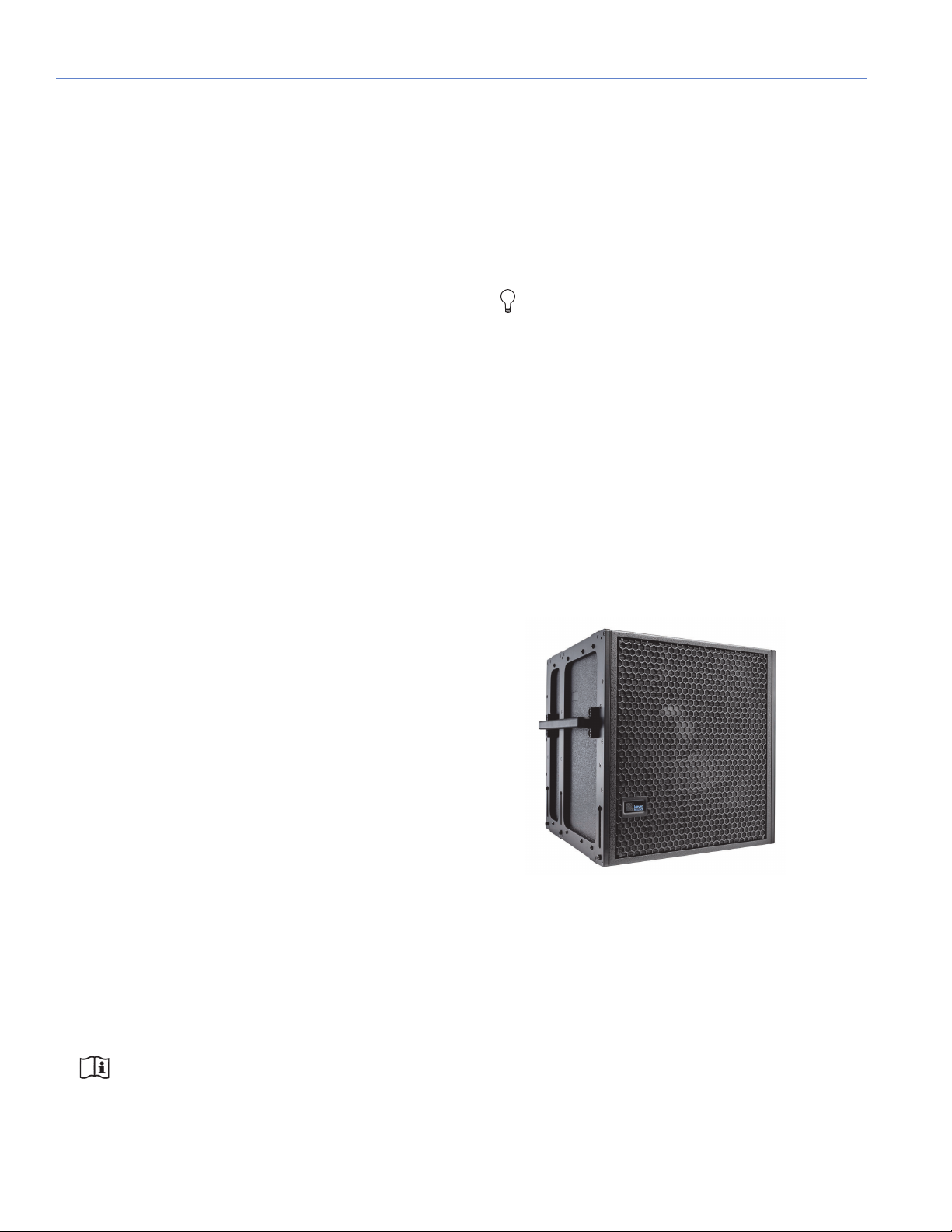
systems can be deployed in combination with the 750-LFC
very compact low-frequency control element (Figure 1),
extending the system frequency response down to 35 Hz, or
the 900-LFC compact low-frequency control element
(Figure 2), which supports frequencies down to 30 Hz.
RIG-READY
The UPQ-D1/D2/D3 loudspeakers provide extremely high
power output with low distortion in vented two-way
enclosures. The durable trapezoidal enclosures have a
slightly textured black finish, an integral stand mount
receptacle, and versatile rigging end plates. Made of
heavy-duty, high-strength, corrosion-resistant 6061T6
aluminum, the end plates incorporate threaded M10
attachment points.
QuickFly
array plate and MYA-UPQ mounting yoke. UPQ-D Series
loudspeakers are available in custom color finishes, allowing
them to blend in with any environment. Weather-protected
versions with treated-wood enclosures and a rain hood to
safeguard the rear of the loudspeaker and connectors from
the elements are also available.
10
®
rigging options include the MPA-UPQ pickup and
NOTE: Complete acoustical, electrical and
physical specifications are covered in
Appendix C on page 41.
Figure 1: The 750-LFC Very Compact Low Frequency Control Element
Page 11

Figure 2: The 900-LFC Compact Low Frequency Control Element
The UPQ-D Series are supported by Meyer Sound’s MAPP
acoustical prediction program and the Galileo™ GALAXY
Network Platform loudspeaker management system. After a
Meyer Sound system is designed and installed, its
performance can be confirmed using a SIM
audio analyzer
system.
UPQ-D SERIES OPERATING INSTRUCTIONS
11
Page 12

CHAPTER 1: INTRODUCTION
12
Page 13
CHAPTER 2: POWER REQUIREMENTS
!
!
Neutral
Earth/Ground
Line 1 (120 V AC)
Line 3 (120 V AC)
Line 2 (120 V AC)
Loudspeaker
(120 V AC)
Loudspeaker
(120 V AC)
Loudspeaker
(120 V AC)
Neutral
Earth/Ground
Loudspeaker
(208 V AC)
Loudspeaker
(208 V AC)
Loudspeaker
(208 V AC)
Line 1 (120 V AC)
Line 3 (120 V AC)
Line 2 (120 V AC)
The UPQ-D Series loudspeakers combine advanced
loudspeaker technology with equally advanced power
capabilities. Understanding power distribution, voltage and
current requirements, and electrical safety guidelines is critical
for the safe operation of the UPQ-D Series loudspeakers.
AC POWER DISTRIBUTION
All components in an audio system (self-powered
loudspeakers, mixing consoles, and processors) must be
properly connected to an AC power distribution system,
ensuring that AC line polarity is preserved and that all
grounding points are connected to a single node or common
point using the same cable gauge (or larger) as the neutral and
line cables.
CAUTION: Make sure the voltage received by
the UPQ-D Series loudspeakers remain within
their 90–264 V AC operating range. In addition, the
ground line must always be used for safety reasons and
the line-to-ground voltage should never exceed
250 V AC (typically 120 V AC from line to ground).
CAUTION: Before applying AC power to any
Meyer Sound self-powered loudspeaker, make
sure that the voltage potential difference between the
neutral and earth-ground lines is less than 5 V AC when
using single-phase AC wiring.
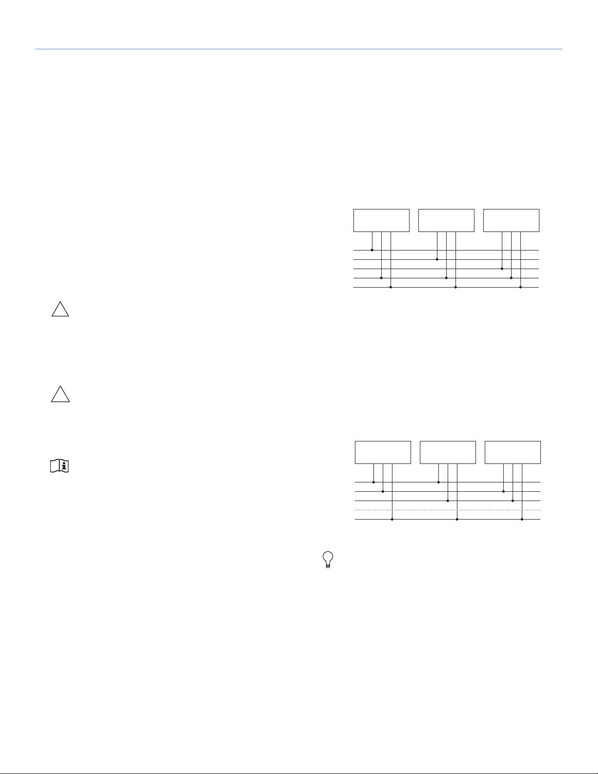
120 V AC, 3-Phase Wye System (Single Line)
Line-Neutral-Earth/Ground
Figure 3 illustrates a basic 120 V AC, 3-phase Wye distribution
system with the loudspeaker load distributed across all three
phases and with each loudspeaker connected to a single line
and common neutral and earth/ground lines. This system
delivers 120 V AC to each loudspeaker.
Figure 3: 120 V AC, 3-Phase Wye System (Single Line to Loudspeakers)
120 V AC, 3-Phase Wye System (Two Lines)
Line-Line-Earth/Ground
Figure 4 illustrates a 120 V AC, 3-phase Wye distribution
system with each loudspeaker connected to two lines and a
common earth/ground line. This configuration is possible
because the UPQ-D Series tolerate elevated voltages from the
ground line and does not require a neutral line. This system
delivers 208 V AC to each loudspeaker.
NOTE: Improper grounding of connections
between loudspeakers and the rest of the audio
system may produce noise or hum, or cause serious
damage to the input and output stages of the system’s
electronic components.
Figure 4: 120 V AC, 3-Phase Wye System (Two Lines to Loudspeakers)
TIP: The 120 V AC, 3-phase Wye system with two
lines is recommended because it allows
loudspeakers to draw less current than with single-line
systems, thereby reducing voltage drop due to cable
resistance. It also excludes the potential of varying
ground to neutral voltages producing an audible hum.
13
Page 14
CHAPTER 2: POWER REQUIREMENTS
Neutral
Earth/Ground
Line 1 (230 V AC)
Line 3 (230 V AC)
Line 2 (230 V AC)
Loudspeaker
(230 V AC)
Loudspeaker
(230 V AC)
Loudspeaker
(230 V AC)
!
!
230 V AC, 3-Phase Wye System (Single Line)
Line-Neutral-Earth/Ground
Figure 5 illustrates a basic 230 V AC, 3-phase Wye
distribution system with the loudspeaker load distributed
across all three phases and with each loudspeaker
connected to a single line and common neutral and earth/
ground lines. This system delivers 230 V AC to each
loudspeaker.
Figure 5: 230 V AC, 3-Phase Wye System (Single Line to Loudspeakers)
CAUTION: For 230 V AC, 3-phase Wye
systems, never connect two lines to the AC
input of a UPQ-D Series loudspeaker, as the resulting
voltage would exceed the upper voltage limit
(275 V AC) and will damage the loudspeaker.
grounded outlet. To operate safely and effectively, it is
extremely important that the entire system be properly
grounded.
The AC Input connector also supplies power to any
additional loudspeakers connected to the loudspeaker’s
gray Loop Output connector.
CAUTION: When looping AC power for
loudspeakers, do not exceed the current
capability of the AC Input connector (20 A) or the
included AC power cable (15 A). Consider the total
current draw for all loudspeakers on the circuit,
including the first loudspeaker (Table 1).
AC Loop Output (Gray)
The gray AC Loop Output connector allows multiple
UPQ-D Series loudspeakers to be looped and powered from
a single power source. The 3-conductor powerCON 20 is
rated at 20 A and uses a locking connector that prevents
accidental disconnections. For applications that require
multiple UPQ-D Series loudspeakers, connect the AC Loop
Output of the first loudspeaker to the AC Input of the second
loudspeaker and so forth.
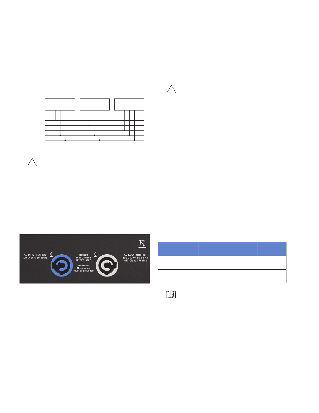
AC CONNECTORS
The UPQ-D Series loudspeaker user panel includes two
powerCON 20 connectors (Figure 6), one for AC Input (blue)
and one for AC Loop Output (gray).
Figure 6: AC Input (Left) and AC Loop Output (Right) Connectors
AC Input (Blue)
The blue AC Input connector supplies power to a
UPQ-D Series loudspeaker. The 3-conductor powerCON 20
is rated at 20 A and uses a locking connector that prevents
accidental disconnections. A 10-foot AC power cable, rated
at 15 A, is included with each loudspeaker. If the included
AC power cable is replaced, make sure to use a cable with
the appropriate power plug (on the other end) for the region
where the unit will be operated. The UPQ-D Series require a
The maximum number of loudspeakers that can be looped
from the AC Loop Output connector is determined by the
voltage of the power source, the current draw of the looped
loudspeakers, the circuit breaker rating, and the rating of the
AC power cable connected to the first UPQ-D Series
loudspeaker (Table 1).
Ta bl e 1 : M ax i mu m U PQ-D 1/ 2/ 3 t h at C a n B e Lo o pe d w i th A C P o we r
Circuit Breaker/
Connector Rating
15 A
20 A
115 V AC 230 V AC 100 V AC
6 looped
(7 total)
9looped
(10 total)
13 looped
(14 total)
18 looped
(19 total)
5looped
(6 total)
8looped
(9 total)
NOTE: Current draw for a UPQ-D Series
loudspeaker is dynamic and fluctuates as
operating levels change. The indicated number of
loudspeakers that can be looped assumes that
operating levels are normal and not such that
loudspeakers are constantly limiting.
UPQ-D Series loudspeakers ship with a gray powerCON 20
cable mount connector, rated at 20 A, for assembling AC
looping cables. Assembled 1-meter AC looping cables
(PN 28.115.032.03) are also available from Meyer Sound.
14
Page 15
UPQ-D SERIES OPERATING INSTRUCTIONS
L
N
PE
SIDE FRONT REAR
U.S./Canada, 60 Hz
Black (L)
Europe, 50 Hz
Green (E)
White (N)
Brown (L)
Blue (N)
Green/
yellow (E)
!
!
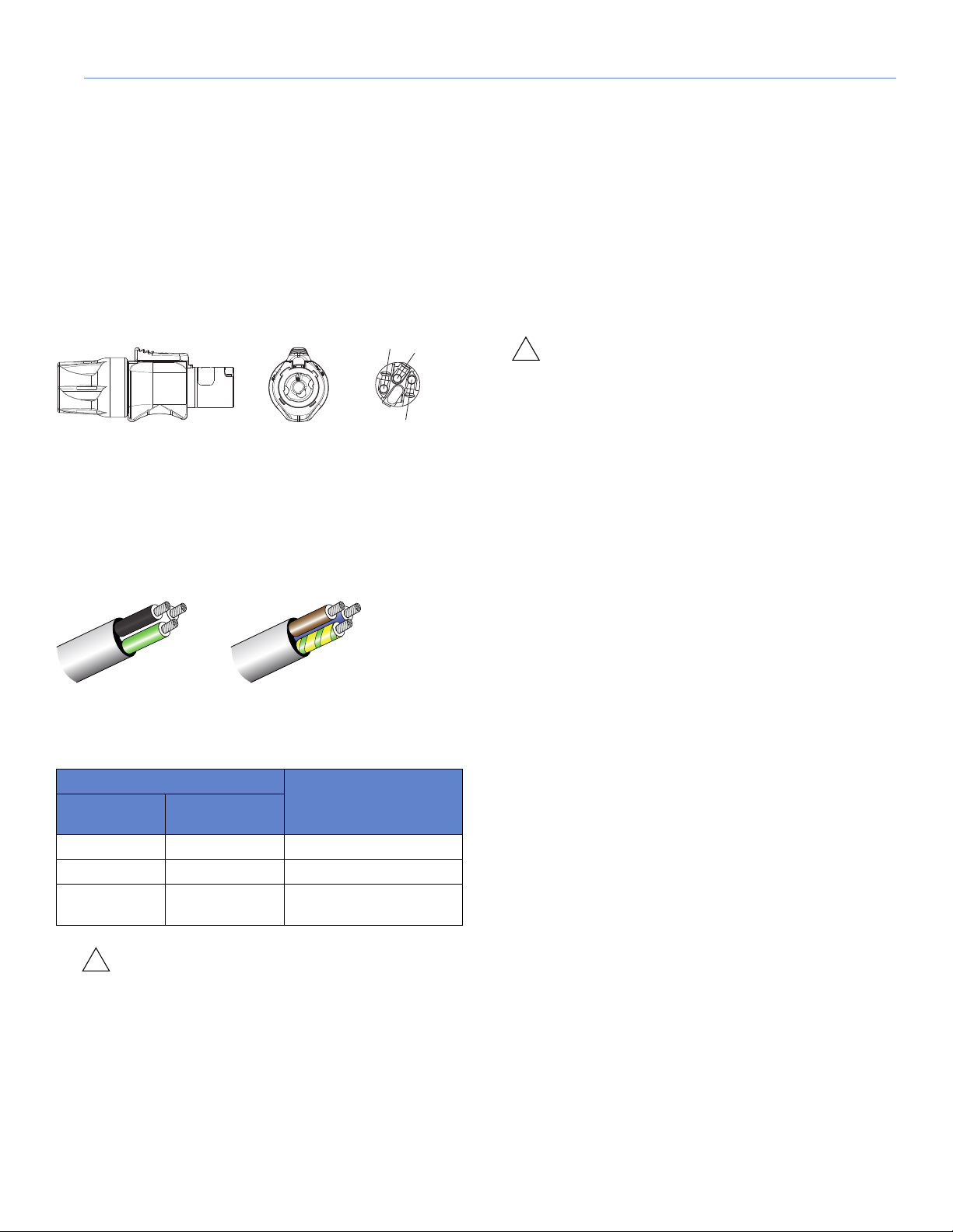
WIRING AC POWER CABLES
UPQ-D Series loudspeakers ship with a gray powerCON 20
cable mount connector, rated at 20 A, for assembling AC
looping cables (Figure 7). The pins on the powerCON 20 cable
mount connector are labeled as follows:
• L (Line)
• N (Neutral)
• PE (Protective Earth or Ground)
Figure 7: powerCON20Cable Mount Connector
How AC power cables are wired is determined by the type of
AC power distribution system used (see “AC Power
Distribution” on page 13). When wiring AC power cables for
single-line systems, use one of the wiring schemes shown in
Figure 8 and described in Table 2:
VOLTAGE REQUIREMENTS
A UPQ-D Series loudspeaker operates as intended when
receiving AC voltage within the following range:
• 90–264 V AC, 50–60 Hz
If the voltage drops below 90 V, the loudspeaker uses stored
power to continue operating temporarily; the loudspeaker
powers off if the voltage does not return to its operating range.
If the voltage rises above 275 V, the power supply could
become damaged.
CAUTION: The power source for a UPQ-D Series
loudspeaker should always operate within the
required operating range, at least a few volts from the
upper and lower limits. This approach ensures that AC
voltage variations from the service entry—or peak
voltage drops due to cable runs—will not cause the
loudspeaker’s amplifier to cycle on and off or cause
damage to the power supply.
CURRENT REQUIREMENTS
Current draw for loudspeakers is dynamic and fluctuates as
operating levels change. Because different cables and circuit
breakers heat up at varying rates, it is important to understand
the following types of current ratings and how they affect
circuit breaker and cable specifications.
Figure 8: AC Wiring Scheme
Ta bl e 2: AC W ir i ng S ch e me
Wire Color Attach to the
U.S. / Canada
60 Hz
Black Brown Hot or live (L)
White Blue Neutral (N)
Green Green and Yellow
European
50 Hz
Following
Te rm i n al
Protective earth / ground
(E or PE)
CAUTION: When wiring AC power cables and
distribution systems, it is important to preserve
AC line polarity and connect the earth ground at both
ends of the cable. A UPQ-D Series loudspeaker
requires a grounded connection. Always use a
grounded outlet and plug. It is extremely important that
the system be properly grounded to operate safely and
properly. Do not ground-lift the AC cable.
• Idle Current — The maximum rms current during idle
periods.
• Maximum Long-Term Continuous Current — The
maximum rms current during a period of at least
10 seconds. The maximum long-term continuous current is
used to calculate temperature increases for cables and to
ensure that the size and gauge of each cable conforms to
electrical code standards. This current rating is also used
to select appropriately rated, slow-reacting thermal
breakers, which are recommended for loudspeaker power
distribution. In addition, the maximum long-term
continuous current can be used to calculate the AC
looping capability for UPQ-D Series loudspeakers.
• Burst Current — The maximum rms current during a
period of around 1 second. The burst current is used as a
rating for magnetic breakers. It is also used for calculating
the peak voltage drop in long AC cable runs according to
the following formula:
V pk (drop) = I pk x R (cable total)
• Maximum Instantaneous Peak Current — A rating for
fast-reacting magnetic breakers.
15
Page 16

CHAPTER 2: POWER REQUIREMENTS
!
Use the information in Appendix C, “UPQ-D Series
Specifications.” to select the appropriate cable gauge and
circuit breaker ratings for the system’s operating voltage.
The minimum electrical service amperage required by a
loudspeaker system is the sum of the maximum long-term
continuous current for all loudspeakers. An additional
30 percent above the combined Maximum Long-Term
Continuous amperages is recommended to prevent peak
voltage drops at the service entry.
NOTE: For best performance, the AC cable
voltage drop should not exceed 10 V
(10 percent at 115 V and 5 percent at 230 V). This
approach ensures that the AC voltage variations from
the service entry—or peak voltage drops due to longer
cable runs—do not cause the amplifier to cycle on and
off.
INTELLIGENT AC POWER SUPPLY
The UPQ-D Series Intelligent AC™ power supply
automatically selects the correct operating voltage (allowing
the loudspeaker to be used internationally without manually
setting voltage switches), eliminates high inrush currents
with soft-start power up, suppresses high-voltage transients
up to several kilovolts, filters common mode and differential
mode radio frequencies (EMI), and sustains operation
temporarily during low-voltage periods.
Powering on UPQ-D Series
When powering on a UPQ-D Series loudspeaker, the
following startup events take place over several seconds.
1. Audio output is muted.
2. Voltage is detected and the power supply mode is automatically adjusted as necessary.
3. The power supply ramps up.
4. On the user panel, the Active/Status LED flashes multiple
colors successively.
5. The Active/Status LED turns solid green, indicating the
loudspeaker is unmuted and ready to output audio.
CAUTION: If the Active/Status LED does not
turn solid green, or the UPQ-D Series
loudspeaker does not output audio after 10 seconds,
remove AC power immediately and verify that the
voltage is within the required range. If the problem
persists, contact Meyer Sound Technical Support.
16
Page 17

ELECTRICAL SAFETY GUIDELINES
Earth ground
Chassis ground
Make sure to observe the following important electrical and
safety guidelines.
• The powerCON 20 connector should not be engaged or
disengaged when under load or energized. Either
de-energize or disconnect the other end of the cable.
• UPQ-D Series loudspeakers require grounded outlets.
Always use a grounded outlet and plug.
UPQ-D SERIES OPERATING INSTRUCTIONS
• Do not use a ground-lifting adapter or cut the AC cable
ground pin.
• Do not exceed the current capability of the 20 A AC Input
connector for the loudspeaker. When looping
loudspeakers, consider the total current draw for all
loudspeakers on the circuit, including the first loudspeaker.
• Make sure the AC power cable for the loudspeaker has the
appropriate power plug (on the other end) for the area in
which the loudspeaker will be operated. In addition, the AC
power cable must be rated for the total current draw of all
loudspeakers looped from the power source.
• Do not operate the unit if the power cable is frayed or
broken.
• Keep all liquids away from UPQ-D Series loudspeakers to
avoid hazards from electrical shock.
17
Page 18

CHAPTER 2: POWER REQUIREMENTS
18
Page 19

CHAPTER 3: AMPLIFICATION AND AUDIO CONNECTORS
The UPQ-D Series drivers are powered by a proprietary
2-channel, open-loop, class D amplifier. The audio signal is
processed with electronic crossover, correction filters for flat
phase and frequency responses, and by driver protection
circuitry. Each channel has peak and rms limiters that prevent
driver over-excursion and regulate voice coil temperatures.
The UPQ-D Series user panel (Figure 9) includes Input and Loop
output connectors for audio, Limit and Active LEDs, and RMS
connectors and controls (see Chapter 6, “RMS Remote
Monitoring System”).
AUDIO CONNECTORS
The UPQ-D Series loudspeakers are available with XLR 3-pin
(Figure 10) or 5-pin connectors (Figure 11) for audio Input and
audio Loop output. XLR 5-pin connectors accommodate both
balanced audio and RMS signals.
Figure 10: XLR 3-Pin Audio Connectors, Input and Loop Output
Figure 9: UPQ-D Series User Panel (3-pin XLR and optional RMS)
Figure 11: XLR 5-Pin Audio Connectors, Input and Loop Output
Audio Input (XLR 3-Pin or 5-Pin Female)
The XLR 3-pin or 5-pin female Input connector accepts
balanced audio signals with an input impedance of 10 k
connector uses the following wiring scheme:
• Pin 1 — 1 kΩ to chassis and earth ground (ESD clamped)
• Pin 2 — Signal (+)
• Pin 3 — Signal (–)
• Pin 4 — RMS (polarity insensitive)
• Pin 5 — RMS (polarity insensitive)
• Case — Earth (AC) ground and chassis
NOTE: Pins 4 and 5 (RMS) are included only with
XLR 5-pin connectors.
Ω. The
19
Page 20

CHAPTER 3: AMPLIFICATION AND AUDIO CONNECTORS
!
Pins 2 and 3 carry the input as a differential signal. Pin 1 is
connected to earth through a 1 kΩ, 1000 pF, 15 V clamped
network. This circuitry provides virtual ground lift for audio
frequencies while allowing unwanted signals to bleed to
ground. Make sure to use balanced XLR audio cables with
pins 1–3 connected on both ends. Telescopic grounding is
not recommended and shorting an input connector pin to the
case may cause a ground loop, resulting in hum.
TIP: If the loudspeaker produces unwanted noise
or hiss, disconnect its input cable. If the noise
stops, there is most likely nothing wrong with the
loudspeaker. To locate the source of the noise, check
the source audio, AC power, and electrical ground.
Audio Loop Output (XLR 3-Pin or 5-Pin Male)
The XLR 3-pin or 5-pin male Loop output connector allows
multiple loudspeakers to be looped from a single audio
source. The Loop output connector uses the same wiring
scheme as the Input connector (see “Audio Input (XLR 3-Pin
or 5-Pin Female)” on page 19). For applications that require
multiple UPQ-D Series loudspeakers, connect the Loop
output of the first loudspeaker to the Input of the second
loudspeaker and so forth.
NOTE: The Loop output connector is wired in
parallel to the Input connector and transmits
the unbuffered source signal even when the
loudspeaker is powered off.
Calculating Load Impedance for Looped Audio Signals
To a v oid d i st o rt i on w h en lo o pin g m ul ti pl e l ou d spe ak e rs ,
make sure the source device can drive the total load
impedance of the looped loudspeakers. In addition, the
source device must be capable of delivering approximately
20 dBV (10 V rms into 600
the operating bandwidth of the loudspeakers.
Ω) to yield the maximum SPL over
NOTE: Most source devices are capable of
driving loads no less than 10 times their output
impedance.
TIP: Audio outputs from Meyer Sound’s Galileo
GALAXY Network Platform have an output
impedance of 50 ohms. Each output can drive up to 20
Meyer Sound (10 k
CAUTION: Make sure that all cables for looped
loudspeakers are wired correctly (Pin 1 to
Pin 1, Pin 2 to Pin 2, and so forth) to prevent the
polarity from being reversed. If one or more
loudspeakers in a system have reversed polarity,
frequency response and coverage will be significantly
degraded.
Ω) loudspeakers without distortion.
TRUPOWER LIMITING
The UPQ-D Series loudspeakers employ Meyer Sound’s
®
advanced TruPower
constant driver impedance and set the limiting threshold by
measuring voltage alone. This method is inaccurate, because
driver impedances change as frequency content in the source
material changes, and as thermal values for the loudspeaker’s
voice coil and magnet vary. Consequently, conventional
limiters often begin limiting prematurely, which reduces
system headroom and dynamic range.
In contrast, TruPower limiting anticipates varying driver
impedances by measuring both current and voltage to
compute the actual power dissipation in the voice coil. This
approach improves performance, both before and during
limiting, by allowing the driver to produce the maximum SPL
across its entire frequency range while also retaining signal
peaks. TruPower limiting also eliminates power compression
at high levels over lengthy periods, which helps regulate voice
coil temperatures, thereby extending the life of the driver.
l im it in g . Co n v en ti o n al li m i te rs a s su m e a
To c a lc ul a t e t he lo a d i m pe d an ce f o r th e l oo p e d l ou d s pe a k er s ,
divide 10 k
the number of looped loudspeakers. For example, the load
impedance for 10 UPQ-D Series loudspeakers is 1000
(10 k
source device should have an output impedance of 100
less. This same rule applies when looping a UPQ-D Series
loudspeaker with other Meyer Sound self-powered
loudspeakers.
20
Ω (th e input i mpedanc e for a si ngle lo udspeak er) by
Ω/ 10). To drive this number of looped loudspeakers, the
Ω
Ω or
Page 21

UPQ-D SERIES OPERATING INSTRUCTIONS
!
!
!
!
HF and LF Limit LEDs
The low- and high-frequency drivers for UPQ-D Series
loudspeakers are powered by separate amplifier channels, each
with their own limiter. Limiting activity is indicated with two Limit
LEDs on the user panel. The top Limit LED (Figure 12) indicates
limiting for the high-frequency channel and the bottom Limit
LED indicates limiting for the low-frequency channel.
Figure 12: UPQ-D1/2/3 Limit LEDs
When engaged, the limiters not only protect the drivers but also
prevent signal peaks from causing excessive distortion in the
amplifier channels, thereby preserving headroom and
maintaining smooth frequency response at high levels. When
levels return to normal, below the limiter thresholds, limiting
ceases.
A UPQ-D Series loudspeaker performs within its acoustical
specifications at normal temperatures when the Limit LEDs are
unlit, or when the LEDs are lit for 2 seconds or less and then turn
off for at least 1 second. If the LEDs remain lit for longer than
3 seconds, the loudspeaker enters hard limiting where:
• Increases to the input level have no effect
• Distortion increases due to clipping
If a loudspeaker is overheating (for RMS-equipped
loudspeakers, one can verify this situation in Compass RMS), a
reduction in SPL may be necessary. If after a reduction in SPL
and an appropriate cooling period the Active/Status LED
continues to flash red (does not return to solid green), contact
Meyer Sound Technical Support.
If the Active/Status LED flashes red and the loudspeaker does
not output audio, contact Meyer Sound Technical Support
immediately.
CAUTION: If a UPQ-D Series loudspeaker
system consistently overheats before reaching
the desired SPL, consider adding more units to the
system.
NOTE: During startup, the On/Status LED flashes
multiple colors successively. For more
information about the power on sequence, see
“Intelligent AC Power Supply” on page 16.
TIP: When a UPQ-D Series loudspeaker is
connected to an RMS network, the Compass RMS
software provides additional feedback about the
loudspeaker’s hardware status and operating
temperature. For more information, see Chapter 6, “RMS
Remote Monitoring System.”
AMPLIFIER COOLING SYSTEM
The UPQ-D Series loudspeaker is convection cooled. The
amplifier’s heat sink provides natural convection cooling from
the air flowing near its fins.
• Drivers are subjected to excessive heat and excursion,
thereby compromising their lifespan
CAUTION: The Limit LEDs indicate when a safe,
optimum level is exceeded. If a UPQ-D Series
loudspeaker system begins to limit before reaching the
desired SPL, consider adding more units to the system.
CAUTION:
ON/STATUS LED
During normal operation, when a UPQ-D Series loudspeaker is
powered on, the On/Status LED is solid green. If the
loudspeaker encounters a hardware fault, or the unit begins to
overheat, the LED flashes red. In some instances, the
loudspeaker will continue to output audio while the LED flashes
red, though with a reduction in the limiter threshold and acoustic
output to protect the loudspeaker.
CAUTION: To ke e p a UPQ -D Se ri es l ou dsp ea ke r
from overheating, allow at least 3 inches behind
the loudspeaker for proper ventilation.
TIP: The UPQ-D Series loudspeaker heat sink can
reach temperatures up to 80° C (176° F) during
extreme operation. Wait 15 minutes for the unit to cool
before touching.
21
Page 22

CHAPTER 3: AMPLIFICATION AND AUDIO CONNECTORS
22
Page 23

CHAPTER 4: ADDING LOW FREQUENCY CONTROL
!
A UPQ-D Series loudspeaker system can be deployed with
Meyer Sound self-powered low frequency control elements
(see Table 3). These subwoofers achieve very low frequency
responses and extend the system response appreciably,
increasing the overall acoustic power of the system in the
lowest frequencies.
The ideal ratio of UPQ-D Series loudspeakers to low
frequency control element depends on the following
variables:
• Subwoofer model
• System configuration
• Frequency content of the source material
• Headroom required for low frequencies
For most applications, the ratios in Table 3 should yield
good results.
Ta bl e 3: Re c o mm e nd e d Meyer Sound Subwoofer
Subwoofer Frequency
Response
USW-210P 32–123 Hz ±4 dB 1:1 for most applications
750-LFC 37–110 Hz ±4 dB 1:1 for most applications
900-LFC 32–115 Hz ±4 dB 2:1 for most applications
1100-LFC 30–85 Hz ±4 dB 4:1 for most applications
Recommended Ratio
(Number of UPQ-D Series per
Subwoofer)
1:2 for applications requiring
more low end
1:1 for applications requiring
extreme low end
ADDING SUBWOOFERS BY DAISY-CHAINING
Full-range signals can be connected directly to
Meyer Sound self-powered loudspeakers, because the
loudspeakers have built-in active crossovers. Subwoofers
can be added to a UPQ-D Series system by simply
daisy-chaining them to the UPQ-D Series loudspeakers.
When UPQ-D Series loudspeakers are coplanar, or they are
very close together (about four to six feet like in the case of
pole mounting), the phase response will work well in the
area of interaction and the result will be a fairly flat
frequency response. However, the response will show an
increase in the 60–200 Hz range where the response of the
loudspeakers overlaps.
NOTE: If the subwoofer’s Limit LEDs begin to
light before reaching the required SPL, consider adding more subwoofers to meet the SPL
requirements without exposing the drivers to excessive heat and excursion.
USING A PROCESSOR
In larger systems when individual control for the
UPQ-D Series loudspeakers and subwoofers are needed or
desired, if the UPQ-D Series loudspeakers and subwoofer
are more than six feet apart, or if a delay is required between
them, use a measurement system like Meyer Sound’s SIM
to determine appropriate delay and polarity settings.
CAUTION: Make sure the source signal is
sufficient to drive the total load impedance of
the daisy-chained loudspeakers (see “Calculating
Load Impedance for Looped Audio Signals” on
page 20).
TIP: MAPP can be used to accurately predict
the appropriate loudspeaker deployment and
subwoofer integration for loudspeaker systems,
complete with coverage data, system delay and
equalization settings, rigging information, and
detailed design illustrations. For more information,
see “MAPP System Design Tool” on page 33.
To d a is y -c ha i n t he su g ges te d n u mbe r o f U PQ- D S eri es
loudspeakers for the selected subwoofer (see Table 1):
1. Connect the source signal to the Input of the first
UPQ-D Series loudspeaker, then connect the Loop
output of the first loudspeaker to the Input of the second
loudspeaker and so forth.
2. Connect the Loop output of the last UPQ-D Series
loudspeaker in the chain to the subwoofer Input.
23
Page 24

CHAPTER 4: ADDING LOW FREQUENCY CONTROL
24
Page 25

CHAPTER 5: QUICKFLY RIGGING
The UPQ-D Series loudspeakers are compatible with
®
Meyer Sound’s QuickFly
system, a comprehensive
collection of custom-designed rigging, flying, and mounting
options. Comprising rugged, reliable, and easy-to-configure
components, QuickFly supports deployment of UPQ-D
Series loudspeakers as either individual loudspeakers or as
arrays at precise angles to take full advantage of their
directional components. The top and bottom plates for the
UPQ-D Series cabinet are constructed of heavy-duty,
high-strength, corrosion-resistant 6061-T6 aluminum and
include threaded metric holes (for M10 screws) for easy
connection to QuickFly rigging and third-party mounting
options.
IMPORTANT SAFETY CONSIDERATIONS!
When installing Meyer Sound loudspeakers, the following
precautions should always be observed:
• All Meyer Sound products must be used in accordance
with local, state, federal, and industry regulations. It is
the owner’s and user’s responsibility to evaluate the
reliability of any rigging method for their application.
Rigging should only be carried out by experienced
professionals.
BASIC EYE BOLT RIGGING
The UPQ-D Series loudspeaker ships with two M10 threaded,
25 mm eye bolts that attach to the top or bottom of the
loudspeakers and can be used to suspend them. A minimum
of two eye bolts is required when suspending a single
loudspeaker. The use of two eye bolts provides the added
flexibility of aiming and tilting the loudspeaker for targeted
coverage.
Figure 13: UPQ-D Series Top Plate with Threaded Holes for Eye Bolts
• Use mounting and rigging hardware that has been rated
to meet or exceed the weight being hung.
• Make sure to attach mounting hardware to the building's
structural components (studs or joists), and not just to
the wall surface. Verify that the building's structure and
the anchors used for the installation will safely support
the total weight of the mounted loudspeakers.
• Use mounting hardware appropriate for the surface
where the loudspeaker will be installed.
• Make sure bolts and eye bolts are tightened securely.
Meyer Sound recommends using Loctite
®
on eye bolt
threads and safety cables.
• Inspect mounting and rigging hardware regularly.
Immediately replace any worn or damaged components.
Figure 14: UPQ-D Series Loudspeaker with Two Eye Bolts
NOTE: Up to two UPQ-D Series loudspeakers,
oriented vertically, can be suspended with
Meyer Sound eye bolts at a 5:1 safety factor. For this
configuration, the top loudspeaker would have two
eye bolts installed on its top plate and two eye bolts
installed on its bottom plate for connecting to the
second loudspeaker. Additional M10 eye bolts
(PN 40.185.013.01 for a set of 2) are available from
Meyer Sound.
25
Page 26

CHAPTER 5: QUICKFLY RIGGING
!
UPQ-D SERIES RIGGING ACCESSORIES
To m o ve be y on d t he ba s ic ey e b o lt r i gg i ng , M e ye r S o un d o ff er s U PQ - D S er i es ri gg i ng ac c es s or i es th at fa c il i ta t e m or e
configurations (Table 4).
Ta bl e 4: ULT R A- X 4 0/ 4 2 R i gg i ng O pt i on s
Model Features
MYA-UPQ Mounting Yoke
(PN 40.185.052.01)
MPA-UPQ Array Adapter Plate
(PN 40.185.054.01)
Eye bolts
(PN 40.185.013.01)
The MYA-X40 Yoke suspends a single UPQ-D Series loudspeaker and supports a wide range of
horizontal and vertical adjustments. The bottom bar of the yoke attaches to the bottom of the loudspeaker. The kit includes two M10 x 20mm knobs/washers and two M10 x 1.5 x 70 hex head
screws.
The MPA-UPQ Array Adapter Plate kit includes two plates to facilitate installation of UPQ-D Series
loudspeakers in both horizontal and vertical clusters at angles between 34° and 50°. The kit
includes eight M10 x 20 mm knobs and washers.
Replacement black-coated M10 1.5 x 17 mm eye bolts, quantity 2
POLE-MOUNTING THE UPQ-D SERIES
A single UPQ-D Series loudspeaker may be mounted on a
heavy-duty loudspeaker stand with a standard 38 mm (1.5 in)
pole using its integral pole mount receptacle. The load rating
for the stand must meet or exceed the weight of the
UPQ-D Series loudspeaker (95 lb or 43 kg) and the pole must
be installed according to the manufacturer’s instructions.
THE MYA-UPQ MOUNTING YOKE
The MYA-UPQ (PN 40.185.052.01) mounting yoke suspends
a single UPQ-D Series loudspeaker and allows a wide range
of horizontal and vertical adjustment. The mounting yoke’s
bottom bar attaches to the bottom plate of the loudspeaker
with two M10 mounting screws (included). A “C” or “G”
hanging clamp and steel safety cable (not included) are
required to suspend the MYA-UPQ mounting yoke.
Figure 15: UPQ-D Series Mounted on Pole
CAUTION: Make sure the pole is designed to
support the total weight of the UPQ-D Series
loudspeaker and observe all safety precautions
specified by the pole manufacturer.
26
Figure 16: MYA-UPQ Mounting Yoke
NOTE: The top bar of MYA-UPQ mounting
yoke accommodates hanging clamps with
standard 1/2-inch or 12 mm bolts.
Page 27

UPQ-D SERIES OPERATING INSTRUCTIONS
Shackle holes
when used
horizontally
M10 screw to
loudspeaker
M10 screws to
loudspeaker
Shackle holes
when used
vertically
M10 screw to
loudspeaker
Shackle holes
when used
vertically
!
THE MPA-UPQ ARRAY ADAPTER
The MPA-UPQ array adapter provides a solid connection
between UPQ-D Series loudspeakers to form horizontal and
vertical arrays of up to three loudspeakers. The six M10 screw
holes at the front of the adapter plate are used to adjust the
distance between the loudspeakers to achieve the desired
splay angle (from 34° to 50°) and coverage. The adapter plate
has three rows of shackle holes that offer the flexibility of flying
horizontal and vertical arrays, as well as single loudspeakers.
Suspending Single Loudspeakers Vertically with the MPA-UPQ
A single MPA-UPQ array adapter plate can be used to
suspend a single UPQ-D Series loudspeaker vertically. The
adapter plate attaches to the top center of the loudspeaker
with the included M10 knobs. Shackles attach to the adapter
plate’s middle shackle holes (oriented up).
Figure 17: MPA-UPQ Array Adapter Plate
The MPA-UPQ array adapter kit (PN 40.185.054.01) includes
two plates and eight M10 knobs and washers. A single kit can
create an array of two UPQ-D Series loudspeakers; two kits
are required for an array of three loudspeakers.
Arrays are assembled by attaching the array adapter plates to
the top and bottom plates of the UPQ-D Series loudspeakers
and securing them with the included M10 knobs and washers.
CAUTION: The MPA-UPQ array adapter
supports a maximum of three UPQ-D Series
loudspeakers in an array.
Figure 18: Attaching an Array Adapter Plate
TIP: A second MPA-UPQ array adapter plate
attached to the bottom can be used to pull back
for severe downtilt angles using the last shackle hole.
27
Page 28

CHAPTER 5: QUICKFLY RIGGING
Suspending Single Loudspeakers Horizontally with the MPA-UPQ
Tw o MPA -U PQ a r ra y ad a pt e r pl at e s ca n be u se d t o s u sp e nd
a single UPQ-D Series loudspeaker horizontally. The adapter
plates attach to the top and bottom edges of the loudspeaker
with the included M10 knobs. Shackles attach to the adapter
plate’s side shackle holes (oriented up).
Figure 19: MPA-UPQ Suspending a Single Loudspeaker Horizontally
Vertical Arrays with the MPA-UPQ
MPA-UPQ vertical arrays are constructed by placing adapter
plates on the tops and bottoms of the loudspeakers between
each loudspeaker. The adapter plates are oriented with the
middle shackle row in.
Horizontal Arrays with the MPA-UPQ
MPA-UPQ horizontal arrays are constructed by placing
adapter plates on the tops and bottoms of the loudspeakers
between each loudspeaker. The adapter plates are oriented
with the middle shackle row up.
Figure 21: MPA-UPQ, Vertical Array
NOTE: For a list of available splay angles for
arrayed UPQ-D Series loudspeakers, see
“MPA-UPQ Splay Angles for Arrayed Loudspeakers”
on page 29.
NOTE: Optimal acoustical performance for a
UPQ-D Series array is achieved by using the
adequate number of units as well as selecting the
specific angles between cabinets to fill the
requirements of the application. In general, larger
angles can create a hole in the coverage and smaller
angles can create too much interaction.
NOTE: MAPP, covered in greater detail in
Chapter 6, is the tool of choice to enable users
to make accurate and comprehensive predictions for
optimal coverage(s) during the design phase.
Figure 20: MPA-UPQ, Horizontal Array
28
Page 29

MPA-UPQ Splay Angles for Arrayed
50°
46°
42°
38°
Loudspeakers
The MPA-UPQ array adapter plate has six different M10
screw holes for adjusting the splay angle for arrayed
UPQ-D Series loudspeakers. The following illustrations show
the possible splay angles for arrayed loudspeakers.
UPQ-D SERIES OPERATING INSTRUCTIONS
Figure 24: MPA-UPQ with Loudspeakers Arrayed at 42°
Figure 22: MPA-UPQ with Loudspeakers Arrayed at 50°
Figure 23: MPA-UPQ with Loudspeakers Arrayed at 46°
Figure 25: MPA-UPQ with Loudspeakers Arrayed at 38°
29
Page 30

CHAPTER 5: QUICKFLY RIGGING
34°
Figure 26: MPA-UPQ with Loudspeakers Arrayed at 34°
30
Page 31

CHAPTER 6: RMS REMOTE MONITORING SYSTEM
The UPQ-D Series loudspeakers optionally include an RMS
remote monitoring system module, allowing them to be
connected to an RMS network. RMS reports, in real time, the
status and power usage of multiple Meyer Sound
loudspeakers from a Mac
The RMServer
™
communicates with Meyer Sound
®
or Windows®-based computer.
loudspeakers equipped with RMS modules. RMServer is a
compact, Ethernet-based hardware unit with two FT-10 RMS
data ports. RMServer stores system configurations internally,
eliminating most manual data entry. Systems can be
monitored from a computer at front-of-house or backstage, or
from a laptop anywhere within the venue over WiFi.
NOTE: For the latest RMS system requirements,
visit the Meyer Sound website
(http://www.meyersound.com
).
NOTE: RMS does not control AC power.
COMPASS CONTROL SOFTWARE
Compass Control Software provides extensive system status
and performance data for each loudspeaker via the RMServer
tab including amplifier voltage, limiting activity, power output
and driver status, as well as mute and solo capability.
Loudspeakers are added to the RMS network and assigned a
node name during a one-time discovery procedure. After
loudspeakers are identified on the RMS network, they appear
in Compass RMS as icons that can be customized to suit the
needs of the application (Figure 27).
Individual loudspeakers can be physically identified with the
Wink option in RMS which lights the Wink LED on the RMS
module of that particular loudspeaker. Conversely, a
loudspeaker can be identified in Compass by pressing the
Identify button on the loudspeaker’s RMS module.
Loudspeaker icons can be arranged in Compass RMS and
saved as pages to represent how the loudspeakers have been
deployed in the system. Multiple pages can be saved and
recalled for specific performances and venues.
RMS MODULE
The UPQ-D Series RMS user panel (Figure 28) includes an
Identify button, Remote Mute switch, Wink/Activity LED, and
two Network connectors.
Figure 28: UPQ-D Series RMS Module
NOTE: The Identify button and Wink/Activity LED
on the RMS user panel are used exclusively by
RMS and have no effect on the acoustical or electrical
activity of the loudspeaker.
Figure 27: Compass RMS Window
Identify Button
The Identify button serves the following functions:
• If the loudspeaker has not yet been discovered on the RMS
network (Wink/Activity LED not lit), press the Identify
button to discover it.
• To r e mo v e t he lo u dsp ea k er fr o m t he RM S n e two rk , pr es s
and hold the Identify button during startup (see “Resetting
the RMS Module” on page 32).
• To wink a discovered loudspeaker, press the Identify
button. The Wink LED on the loudspeaker icon in Compass
RMS lights up and the Wink/Activity LED on the
loudspeaker’s RMS user panel turns solid green. Press the
Identify button again to unwink the loudspeaker.
31
Page 32

CHAPTER 6: RMS REMOTE MONITORING SYSTEM
TIP: The loudspeaker can also be winked by
clicking the Wink button on the loudspeaker
icon in Compass RMS.
Wink/Activity LED (Green)
The green Wink/Activity LED indicates the status of the
loudspeaker:
• During startup, the LED flashes green 10 times.
• If the loudspeaker has not yet been discovered on the
RMS network, the LED is not lit after startup.
• If the loudspeaker has been successfully discovered on
the RMS network, the LED flashes green continuously
and flashes more rapidly with increased data activity.
• When the loudspeaker is winked, either by clicking the
Wink button in Compass RMS or by pressing the Identify
button on the RMS user panel, the LED is solid green.
The LED remains solid green until the loudspeaker is
unwinked.
TIP: The Wink function is useful for identifying
the physical loudspeaker corresponding to a
loudspeaker icon in Compass RMS.
Remote Mute Switch
The recessed Remote Mute switch on the UPQ-D Series
RMS module (Figure 29) determines whether Compass RMS
can control muting and soloing of the loudspeaker. The
UPQ-D Series ships from the factory with the switch
enabled.
RMS Network Connectors
The Weidmuller 2-conductor, locking connectors transfer
data to and from the RMS network. Two connectors are
provided to allow for easy connection of multiple
(daisy-chained) loudspeakers on the network. Included with
each RMS-equipped loudspeaker are RMS cable
connectors and mounting blocks for constructing RMS
cables. The mounting blocks allow the Weidmuller
connectors to be securely attached to the RMS module with
screws.
NEURON ID FOR RMS MODULE
Each RMS module has a unique 12-character Neuron ID
(NID) that identifies the loudspeaker on the network. The
NID is automatically detected by RMServer but can also be
entered manually, if necessary, when configuring RMS
systems in Compass RMS without loudspeakers present.
The NID label is located on the RMS user panel near the
orange Network connectors.
RESETTING THE RMS MODULE
The Identify button can be used to reset the UPQ-D Series
RMS module when powering on the loudspeaker. This
action will cause the module to be removed from the RMS
network.
To r e se t t h e R MS m o du l e:
1. Power down the loudspeaker.
2. Press and hold the Identify button.
3. While continuing to hold down the Identify button, power
on the loudspeaker.
Figure 29: Remote Mute Switch
• Disable: When the Remote Mute switch is set to Disable
(to the left), the loudspeaker cannot be muted or soloed
from Compass RMS.
• Enable: When the Remote Mute switch is set to Enable
(to the right), the loudspeaker can be muted and soloed
from Compass RMS.
NOTE: Compass RMS has a preference that
can be set to disable Mute and Solo functions,
eliminating any possibility of accidentally muting
loudspeakers.
32
4. After the Wink/Status LED flashes on and off, release the
Identify button. The RMS module is reset and the
loudspeaker is removed from the RMS network.
Page 33

CHAPTER 7: SYSTEM DESIGN AND INTEGRATION TOOLS
This chapter introduces MAPP, Meyer Sound’s patented
system design tool, the Galileo GALAXY Network Platform,
and SIM, a comprehensive system for measurement and
analysis.
MAPP SYSTEM DESIGN TOOL
The MAPP System Design Tool (Figure 30) is a powerful,
cross-platform application for accurately predicting the
coverage pattern, frequency response, phase response,
impulse response, and SPL capability of single or arrayed
Meyer Sound loudspeakers.
Figure 30: MAPP System Design Tool
MAPP client software allows for configuration of
Meyer Sound loudspeaker systems and definition of the
environment in which they operate, including air temperature,
pressure, humidity, and even the location and composition of
surfaces. Importation of CAD (.DXF) files containing detailed
venue information to act as a visual aid is also possible.
MAPP prediction requests are sent by the client software to
Meyer Sound servers, where complex, high-resolution
(magnitude and phase) polar data is processed with
sophisticated acoustical prediction algorithms. The resulting
predictions are then displayed in the MAPP client software.
TIP: Meyer Sound offers seminars and webinars
on using MAPP. For more information, visit
www.meyersound.com
.
MAPP Capabilities
With MAPP, a user can:
•Simulate different loudspeaker configurations to refine
system designs and determine the best coverage for
intended audience areas
•Model loudspeaker interactions to locate constructive
and destructive interferences, so that loudspeakers can
be re-aimed and repositioned as necessary
Whether planning for fixed installations or for tours with
multiple venues, use MAPP to accurately predict the
appropriate loudspeaker deployment for each job, complete
with coverage data, system delay and equalization settings,
rigging information, and detailed design illustrations. MAPP’s
accurate, high-resolution predictions ensure that systems
will perform as expected, thereby eliminating unexpected
coverage problems and minimizing onsite adjustments.
The key to the accuracy of MAPP’s predictions is
Meyer Sound’s exhaustive database of loudspeaker
measurements. Performance predictions for each
loudspeaker are based on 720 1/48th-octave-band
measurements taken with a SIM audio analyzer (see “SIM
Measurement System” on page 34) in the Meyer Sound
anechoic chamber. The extraordinary consistency between
Meyer Sound loudspeakers guarantees that predictions from
MAPP will closely match their actual performance.
•Place microphones anywhere in the sound field and
predict loudspeaker frequency response, phase
response, and sound pressure levels at each microphone
position
•Determine delay settings for fill loudspeakers using the
Inverse Fast Fourier Transform feature
•Preview the results of signal processing to determine
optimum settings for the best system response
•Automatically calculate load information for arrays to
determine necessary minimum rigging capacity,
front-to-back weight distribution, and center of gravity
location
•Generate and export system images and full-system PDF
reports for client presentations
33
Page 34

CHAPTER 7: SYSTEM DESIGN AND INTEGRATION TOOLS
GALILEO GALAXY NETWORK PLATFORM
The Galileo GALAXY Network Platform is a sophisticated
loudspeaker management tool for controlling all
Meyer Sound speaker types. The GALAXY loudspeaker
processor extends a high level of audio control in driving
and aligning loudspeaker systems with multiple zones. It
provides a powerful tool set for corrective equalization (EQ)
and creative fine-tuning for a full range of applications from
touring to cinema.
Users can readily program the GALAXY processor using
Compass software running on a host computer or via the
Compass Go application for the iPad. Compass Control
Software includes custom-designed settings for each family
of speakers, as well as to integrate families together. For
example, the Product Integration feature matches the phase
characteristics between Meyer speaker families to ensure
the most coherent summation.
Processing tools for inputs and outputs include delay,
parametric EQ and U-Shaping EQ. Output processing also
includes polarity reversal, Low-Mid Beam control (LMBC),
atmospheric correction, and All Pass filters.
The built-in summing and delay matrices allow a user to
easily assign gain and delay values, respectively, at each
cross point. This capability greatly facilitates using one
loudspeaker to satisfy multiple purposes.
Front panel controls let a user intuitively and quickly operate
a GALAXY processor without a computer during live use.
The rear panel includes SIM bus port(s) for direct connection
to Meyer Sound’s SIM audio analyzer, allowing the GALAXY
processor to function as a line switcher for the analyzer.
With this capability, a user can take measurements from any
selection of GALAXY inputs and outputs without patching
beyond a single connection to the analyzer.
The GALAXY 408, GALAXY 816 and GALAXY 816-AES3
processor versions have the same audio processing
capability with different I/O. See www.meyersound.com to
locate their datasheets for more information.
allows application of precise corrections to balance system
response using frequency and phase domain information.
Source Independent Measurement Technique
The SIM audio analyzer implements Meyer Sound’s source
independent measurement technique. This dual-channel
method makes analysis of statistically unpredictable
excitation signals possible. Any excitation signal, within the
desired frequency range, can be used to obtain highly
accurate measurements for acoustical or electronic systems.
For example, during a performance, both the input signal and
the measured output of the loudspeaker system can be
analyzed by SIM and the results can be used to:
•View measurement data as amplitude versus time
(impulse response) or amplitude and phase versus
frequency (frequency response)
•View single-channel frequency domain data with a
logarithmic frequency axis
•Determine and internally compensate for propagation
delays using the SIM Delay Finder
SIM Applications
SIM’s main applications are testing and aligning loudspeaker
systems, which entails:
•Measuring propagation delays between subsystems to
determine appropriate delay times
•Verifying correct polarity
•Measuring and comparing phase responses of
subsystems
•Measuring variations in frequency response caused by the
acoustical environment and the placement and interaction
of loudspeakers to determine corrective equalization
•Optimizing subwoofer integrations
SIM MEASUREMENT SYSTEM
The SIM audio analyzer is a high-resolution audio
measurement system comprising software, hardware,
microphones, and accessory cables. SIM presents measured
audio frequencies at a resolution of 48 points per octave,
where the 48 points per octave are arranged in even
frequency increments in each octave group, equal to the total
frequencies in that octave divided by 48. This resolution
34
•Optimizing loudspeaker arrays
SIM can also be used in the following applications:
•Microphone calibration and equalization
•Transducer evaluation and correction
•Echo detection and analysis
•Vibration analysis
•Architectural acoustics
Page 35

APPENDIX A: MEYER SOUND WEATHER PROTECTION
!
UPQ-D SERIES OPERATING INSTRUCTIONS
The Weather Protection option from Meyer Sound is
intended to increase the useful life of Meyer Sound
loudspeakers when they are installed outdoors and exposed
to different and often harsh weather conditions.
Meyer Sound Weather Protection includes a penetrating
treatment to raw wood, use of special primers, and plating
on all steel parts used (or alternatively, the use of stainless
steel hardware). Weather Protection is designed to prevent
malfunctions caused by harsh operating environments and
slows the accelerated wear and tear that occurs in outdoor
environments.
When Is Weather Protection Advisable?
Weather Protection is strongly recommended for all
permanent outdoor installations where loudspeakers are
directly exposed to the elements. This recommendation
includes desert and semi-arid climates, where protection
against dust and sand is important, and where infrequent
rainstorms can contribute to deterioration of loudspeaker
components.
Weather Protection is also recommended when the
loudspeakers are sheltered from direct exposure to
precipitation, but are nevertheless exposed to prolonged
high humidity, fog or mist. Examples would be installations
on covered outdoor terraces or pavilions.
Weather Protection is further advisable for portable or
touring systems when any significant outdoor use is
anticipated. Even though standard procedures may call for
using external protective measures, these are often not
implemented in time to prevent moisture intrusions that
could lead to premature performance degradation of the
loudspeaker.
Climate Variation and Owner Maintenance
The wear and tear on a loudspeaker will vary significantly
with different climatic conditions. For example, a
weather-protected loudspeaker installed in a
sunlight-exposed location on an ocean pier will experience
much harsher conditions than a loudspeaker in a similar
installation that is shaded by trees and exposed only to
rainfall. The constant exposure to direct UV radiation and a
salt air environment will cause a loudspeaker to wear more
quickly than one with partial UV shielding and exposed only
to freshwater moisture.
air environments, the exterior grille can quickly show signs
of oxidation, causing unsightly discoloration.
Apart from selecting suitable weather protection, the
progress of wear and tear on the loudspeaker can be
slowed by a regular schedule of inspection and cleaning.
This maintenance is particularly necessary in harsh
environments. Inspection and cleaning should include
routine removal of any visible oxidation or environmental
particulates, as these can accelerate metal corrosion or
decay of the cabinet. If installed loudspeakers are not in use
for an extended period, exterior protection or temporary
removal and storage of the loudspeakers should be
considered.
Benefits of Weather Protection
There are several benefits to selecting the Meyer Sound
Weather Protection option:
Functionality—Weather Protection prolongs the service life
of the loudspeaker by preventing premature degradation of
internal components.
Safety—Weather Protection lessens the chance of electrical
malfunctions or structural failures.
WARNING: IT IS THE RESPONSIBILITY OF
PURCHASERS/USERS/OPERATORS TO
SELECT WEATHER PROTECTION WHEN
APPROPRIATE FOR THEIR USE AND TO
PERIODICALLY INSPECT THEIR LOUDSPEAKER
INSTALLATIONS FOR ANY DETERIORATION THAT
MAY LEAD TO SAFETY CONCERNS.
Aesthetics—Weather Protection slows wear and tear on the
exterior of the loudspeaker in harsh conditions. Early signs
of wear and tear on the exterior of the loudspeaker indicate
over-exposure to the elements.
Standards Compliance—Weather Protection helps in
meeting IP ratings for loudspeakers. IP ratings are an
internationally recognized standard often used in
installations involving our products. A further explanation of
IP ratings is given in the “IP Ratings” Section on page 37.
Wear can eventually affect the performance of the
loudspeaker. It also affects aesthetics. For example, in salt
35
Page 36

APPENDIX A: MEYER SOUND WEATHER PROTECTION
WEATHER PROTECTION COMPONENTS
Standard Weather Protection
Meyer Sound designs toward an IP rating of IPX4 (see “IP
Ratings” on page 37) for Standard Weather Protection,
which includes the following components:
•Wood treatment—Prior to cabinet manufacturing, the
raw wood receives a special treatment that penetrates
and stabilizes the wood fibers to withstand a wide range
of temperatures and exposure to extreme humidity.
•Cabinet finishing—The assembled cabinets receive a
highly impervious finish that includes a sealing primer
and a finishing topcoat. The coatings are applied on both
surfaces, with one coat on the interior and two on the
exterior. The final step is a two-part modified acrylic
urethane similar to that used in military applications.
•Driver treatment—All cone drivers are coated with a
water-resistant sealant.
•Exterior protection—Grille frames are coated to resist
corrosion, and all components that mount to the cabinet
use custom gaskets and stainless steel fasteners.
If in doubt about an installation method, contact Meyer
Sound Technical Support for assistance.
Always discuss the environmental conditions of your Meyer
Sound installation with your Sales Manager, and verify the
availability of Weather Protection for your selected
loudspeaker models. The Sales Manager, together with
Te ch n ic a l Su p po r t, wi l l v er i fy th e a pp ro pr i at e l ev e l o f
weather protection for the loudspeakers and related rigging
hardware.
•Removable rain hood—The rain hood is designed to
shield connectors even in wind-driven rain.
INSTALLATION PRACTICES
Meyer Sound assumes normal and accepted installation
practices are used when installing Meyer Sound
Loudspeakers outdoors. Deviation from such practices may
cause weather protection to be ineffective and void the
warranty for the loudspeaker.
Examples of unacceptable and acceptable installation
practices include:
•Loudspeakers installed outdoors should not face
upward.
•Loudspeakers with a rain hood should be installed in
such a way that the rain hood opening is not facing any
direction but down.
•Meyer Sound-supplied rigging components should not
be modified (for example, by drilling additional holes in a
MUB for mounting to a wall). When an installer/integrator
modifies a Meyer Sound supplied rigging component to
support their installation method, it is considered
compromised and out of warranty.
•All loudspeaker cabling must be installed with a
“drip-loop” or equivalent method to ensure that rain or
water is NOT wicked toward the loudspeaker.
36
Page 37

UPQ-D SERIES OPERATING INSTRUCTIONS
IP RATINGS
IP stands for “Ingress Protection.” The current format for expressing an IP rating is a 2-digit code. The first digit of an IP
rating represents protection from solid objects. The second digit of an IP rating represents protection from water or
moisture. Table 5 provides a chart of IP ratings and the corresponding definitions of the rating.
NOTE: IP ratings only apply to the “ENCLOSURE.” A loudspeaker is considered an enclosure and as such an
IP rating can be applied to it. Rigging hardware is not an enclosure and therefore IP ratings do not apply. Also,
cable and cable-mount connectors used to connect to the loudspeaker are NOT part of the enclosure and therefore
not part of the IP rating. Only the chassis-mounted part of the connector is considered part of the enclosure.
Ta bl e 5: IP R at i ng s D e f in i ti o n C h ar t
First Digit
(Protection against solid
objects)
XCharacteristic numeral is
0No protection.0No protection.
1Protected against solid
2Protected against solid
3Protected against solid
4Protected against solid
5Protected against dust.
Definition Second Digit
(Protection against
liquids)
XCharacteristic numeral is
not required to be specified.
1Protected against vertically
objects over 50 mm.
2Protected against direct
objects over 12 mm.
3Protected against direct
objects over 2.5 mm.
4Protected against direct
objects over 1 mm.
5Protected against
Limited ingress permitted.
Definition
not required to be specified.
falling drops of water.
sprays up to 15° from the
vertical.
sprays up to 60° from the
vertical.
sprays from all directions.
Limited ingress permitted.
low-pressure jets of water
from all directions. Limited
ingress permitted.
6Totally protected against
dust.
6Protected against strong
7Protected against the effect
8Protected against the effect
jets of water from all
directions. Limited ingress
permitted.
of temporary immersion
between 15 cm and 1 m.
of long-term submersion of
1 m or more.
37
Page 38

APPENDIX A: MEYER SOUND WEATHER PROTECTION
38
Page 39

APPENDIX B: RAIN HOODS
!
!
Weather-protected UPQ-D Series loudspeakers include a rain hood for indoor/outdoor touring and sheltered outdoor
installations. Meyer Sound offers two rain hood models: A fixed rigid rain hood for permanent installations and a foldable hood
for portable applications. Please specify the desired rain hood when placing an order.
RIGID RAIN HOOD
The UPQ-D Series rigid removable rain hood is easily attached and removed with the included four screws (Figure 31).
Figure 31: UPQ-D Series with rigid rain hood in Vertical Orientation (left), Horizontal Orientation (top right) and Interior Cable Routing (bottom right))
To a t ta c h t he U P Q- D S e ri e s ri g id ra i n h oo d :
1. Attach any required cables to the UPQ-D Series loudspeaker.
2. Carefully route the cables, so that they wrap over and down the inner rainhood wall.
3. Attach the rain hood to the user panel, and secure it to the center of the panel with its four 6-32 screws.
4. Make sure to tighten the screws to create a good seal against the user panel. The recommended torque value for the screws
is 10–12 in-lb (1.1–1.4 N·m).
CAUTION: There is only one proper vertical loudspeaker orientation and one proper horizontal loudspeaker orien-
tation once the rainhood is installed. See Figure 31.
CAUTION: The weather-protected UPQ-D Series loudspeaker must be mounted with a 0
slight down-tilt. This angle shields the driver from the elements and does not allow water to accumulate. Do not tilt
the cabinet up, as the drivers and cabinet will accumulate water.
NOTE: Weather-protected units using the rigid rainhood are rated IPX4 for water intrusion.
° tilt, or preferably with a
39
Page 40

APPENDIX B: RAIN HOODS
!
!
FOLDABLE RAIN HOOD
The UPQ-D Series foldable rain hood is installed on the unit when shipped. Four screws secure its frame permanently into place
(Figure 32).When using the rainhood, the loudspeaker has only one possible vertical and one possible horizontal position, as all
cables must exit from the lower end of the loudspeaker.
Figure 32: UPQ-D Series with foldable rain hood in vertical (left) and horizontal (right) orientations
To u s e t he UP Q- D S e ri e s f ol d ab l e r ain h o od :
1. Detach the Velcro straps and extend the rain hood.
2. Lift the front flap.
3. Attach any required cables to the UPQ-D Series loudspeaker.
The clear windows allow easy location of the connectors on the user panel.
4. Secure the cable protector with the Velcro attachments.
5. Secure the front flap Velcro edges.
6. Secure the flap on the right/top side of the speaker over the front flap.
7. To stow the rain hood, reverse the steps.
CAUTION: The weather-protected UPQ-D Series loudspeaker must be mounted with a 0
slight down-tilt. This angle shields the driver from the elements and does not allow water to accumulate.
CAUTION: The UPQ-D Series loudspeaker must be oriented so that the cord exits at the bottom of the rainhood.
Use care when installing the loudspeaker to ensure the rainhood is positioned to work properly when unfolded.
° tilt, or preferably with a
40
Page 41

APPENDIX C: UPQ-D SERIES SPECIFICATIONS
UPQ-D SERIES ACOUSTICAL, ELECTRICAL, AND PHYSICAL SPECIFICATIONS
ACOUSTICAL
UPQ-D1 UPQ-D2 UPQ-D3
Operating Frequency
Range
Frequency Response 58 Hz – 18 kHz ±4 dB 61 Hz – 16.5 kHz ±4 dB 57 Hz – 18 kHz ±4 dB
Phase Response 80 Hz to 18 kHz ±45° 80 Hz to 18 kHz ±45° 80 Hz to 18 kHz ±45°
Linear Peak SPL 135.5 dB with crest factor >17 dB
Coverage 80° H x 50° V (–6 dB)
55 Hz – 18 kHz 55 Hz – 18 kHz 55 Hz – 18 kHz
Note: Recommended maximum operating frequency range. Response depends on loading conditions and room
acoustics.
Note: Measured free field with 1/3 octave frequency resolution at 4 meters.
138 dB with 19 dB crest factor
(M-noise), 132 dB (Pink Noise), 135
dB (B-noise)
Note: Linear Peak SPL is measured in free-field at 4 m referred to 1 m. Loudspeaker SPL compression measured
with M-noise at the onset of limiting, 2-hour duration, and 50-degree C ambient temperature is < 2 dB.
M-noise is a full bandwidth (10 Hz–22.5 kHz) test signal developed by Meyer Sound to better measure the loudspeaker’s music performance. It has a constant instantaneous peak level in octave bands, a crest factor that
increases with frequency, and a full bandwidth Peak to RMS ratio of 18 dB. The presence of a greater-than (>) symbol with regard to crest factor indicates it may be higher depending on EQ and boundary loading.
Pink noise is a full bandwidth test signal with Peak to RMS ratio of 12.5 dB.
B-noise is a Meyer Sound test signal used to ensure measurements reflect system behavior when reproducing the
most common input spectrum, and to verify there is still headroom over pink noise.
100° H x 60° V (–10 dB)
(M-noise), 134.5 dB (Pink Noise),
137 dB (B-noise)
50° x 50° (–6 dB)
60° x 60° (–10 dB)
135 dB with crest factor >17 dB
(M-noise), 132 dB (Pink Noise),
134 dB (B-noise)
80° x 80° (–6 dB)
100° x 100° (–10 dB)
TRANSDUCERS
Low Frequency One high-power 15-inch cone driver; 2 nominal impedance
High Frequency One 4-inch diaphragm compression driver; 8 nominal impedance
AUDIO INPUT
Ty pe D if fe r en t ia l, el e ct ro n ic a ll y b a la nc e d
Maximum Common
Mode Range
Connectors XLR 3-pin female input with male loop output; optional XLR 5-pin connector to accommodate both balanced audio
Input Impedance 10 k differential between pins 2 and 3
Wiring Pin 1: Chassis/earth through 1 k, 1000 pF, 15 V clamp network to provide virtual ground lift at audio frequencies
Nominal Input Sensitivity 0 dBV (1 V rms) continuous average is typically the onset of limiting for noise and music
Input Level Audio source must be capable of producing +20 dBV (10 V rms) into 600 to produce maximum peak SPL over the
±15 V DC, clamped to earth for voltage transient protection
and RMS signals.
Pin 2: Signal +
Pin 3: Signal – (optional polarity reversal switch)
Case: Earth ground and chassis
Note: Pins 4 and 5 (RMS) only included with XLR 5-pin connector that accommodates both balanced audio and
RMS signals.
operating bandwidth of the loudspeaker
41
Page 42

APPENDIX C: UPQ-D SERIES SPECIFICATIONS
AMPLIFIER
Ty pe Tw o- c ha nn e l, op e n- lo o p, Cl a ss D
To ta l O ut p ut Po w er 2 2 50 W p ea k
Note: Peak power based on the maximum unclipped peak voltage the amplifier will produce into the nominal load
impedance.
THD, IM TIM <.02%
Cooling Convection
AC POWER
Connectors powerCON 20 input with loop output
Automatic Voltage Selection
Safety Agency Rated
Operating Voltage
Turn On /Turn Of f Poin ts 90 V AC tur n- on , no t ur n- off; i nt er nal fu se pro te ct ion ab ov e 26 5 V AC
Current Draw
Idle Current 0.27 A rms (115 V AC); 0.25 A rms
Maximum Long-Term
Continuous Current
Burst Current 3.7 A rms (115 V AC); 1.9 A rms (230
90–265 V AC, 50–60 Hz
100–240 V AC, 50–60 Hz
(230 V AC); 0.29 A rms (100 V AC)
2.0 A rms (115 V AC); 1.0 A rms (230
V AC); 2.3 A rms (100 V AC)
V AC); 4.3 A rms (100 V AC)
0.27 A rms (115 V AC); 0.25 A rms
(230 V AC); 0.29 A rms (100 V AC)
2.0 A rms (115 V AC); 1.0 A rms (230
V AC); 2.3 A rms (100 V AC)
3.6 A rms (115 V AC); 1.8 A rms (230
V AC); 4.1 A rms (100 V AC)
0.27 A rms (115 V AC); 0.25 A rms
(230 V AC); 0.29 A rms (100 V AC)
2.0 A rms (115 V AC); 1.0 A rms (230
V AC); 2.3 A rms (100 V AC)
3.8 A rms (115 V AC); 1.9 A rms (230
V AC); 4.4 A rms (100 V AC)
Note: AC power cabling must be of sufficient gauge so that under burst current rms conditions, cable transmission
losses do not cause the loudspeaker’s voltage to drop below the specified operating range.
Maximum Instantaneous
Peak Current
Inrush Current <20 A peak <20 A peak <20 A peak
RMS NETWORK (OPTIONAL)
PHYSICAL
Dimensions W: 19.00 in (483 mm) x H: 28.15 in (715 mm) x D: 18.18 in (462 mm);
Weight 95 lb (43 kg)
Enclosure Premium multi-ply birch with slightly textured black finish
Protective Grille Powder-coated, hex-stamped steel with black mesh
Rigging Aluminum end plates on top and bottom with metric M10 threaded points; integral 1-1/2 in (38 mm) pole mount
8.2 A rms (115 V AC); 4.2 A rms (230
V AC); 9.3 A rms (100 V AC)
Tw o- c on du c to r t w is t ed -p a ir ne t wo rk th at reports all operating parameters of amplifiers to system host computer.
receptacle on bottom
7.8 A pk (115 V AC); 4.0 A pk (230 V
AC); 9.1 A pk (100 V AC)
8.4 A pk (115 V AC); 4.1 A pk (230 V
AC); 9.7 A pk (100 V AC)
42
Page 43

ENVIRONMENTAL
Operating Temperature 0 °C to +45 °C
Non Operating
Te mp e ra tu r e
Humidity To 95% at 45 °C (non-condensing)
Operating Altitude To 5,000 m (16,404 ft)
Non Operating Altitude To 12,000 m (39,000 ft)
Shock 30 g 11 msec half-sine on each of 6 sides
Vibration 10 Hz – 55 Hz (0.010 m peak-to-peak excursion)
–40 °C to +75 °C
UPQ-D SERIES OPERATING INSTRUCTIONS
43
Page 44

APPENDIX C: UPQ-D SERIES SPECIFICATIONS
28.15 in
[715 mm]
19.00 in
[483 mm]
34°
1.50 in
[38 mm]
7.88 in
[200 mm]
18.18 in
[462 mm]
14.75 in
[375 mm]
7.88 in
[200 mm]
8.67 in
[220 mm]
UPQ-D1/D2/D3 LOUDSPEAKER DIMENSIONS
Figure 33: UPQ-D1/D2/D3 Loudspeaker Dimensions
44
Page 45

UPQ-D1/D2/D3 WITH RAIN HOOD LOUDSPEAKER DIMENSIONS
28.15 in
[715 mm]
3.85 in
[98 mm]
21.27 in
[540 mm]
15.86 in
[403 mm]
4.96 in
[126 mm]
7.33 in
[186 mm]
19.00 in
[483 mm]
4.62 in
[117.5 mm]
UPQ-D SERIES OPERATING INSTRUCTIONS
Figure 34: UPQ-D1/D2/D3 Loudspeaker with Rain Hood Dimensions
45
Page 46

APPENDIX C: UPQ-D SERIES SPECIFICATIONS
46
Page 47

Page 48

Meyer Sound Laboratories Inc.
2832 San Pablo Avenue
Berkeley, CA 94702
www.meyersound.com
T: +1 510 486.1166
© 2019
Meyer Sound Laboratories Inc. All rights reserved.
UPQ-D1/D2/D3 Operating Instructions PN 05.291.005.01 A
 Loading...