

Page 1
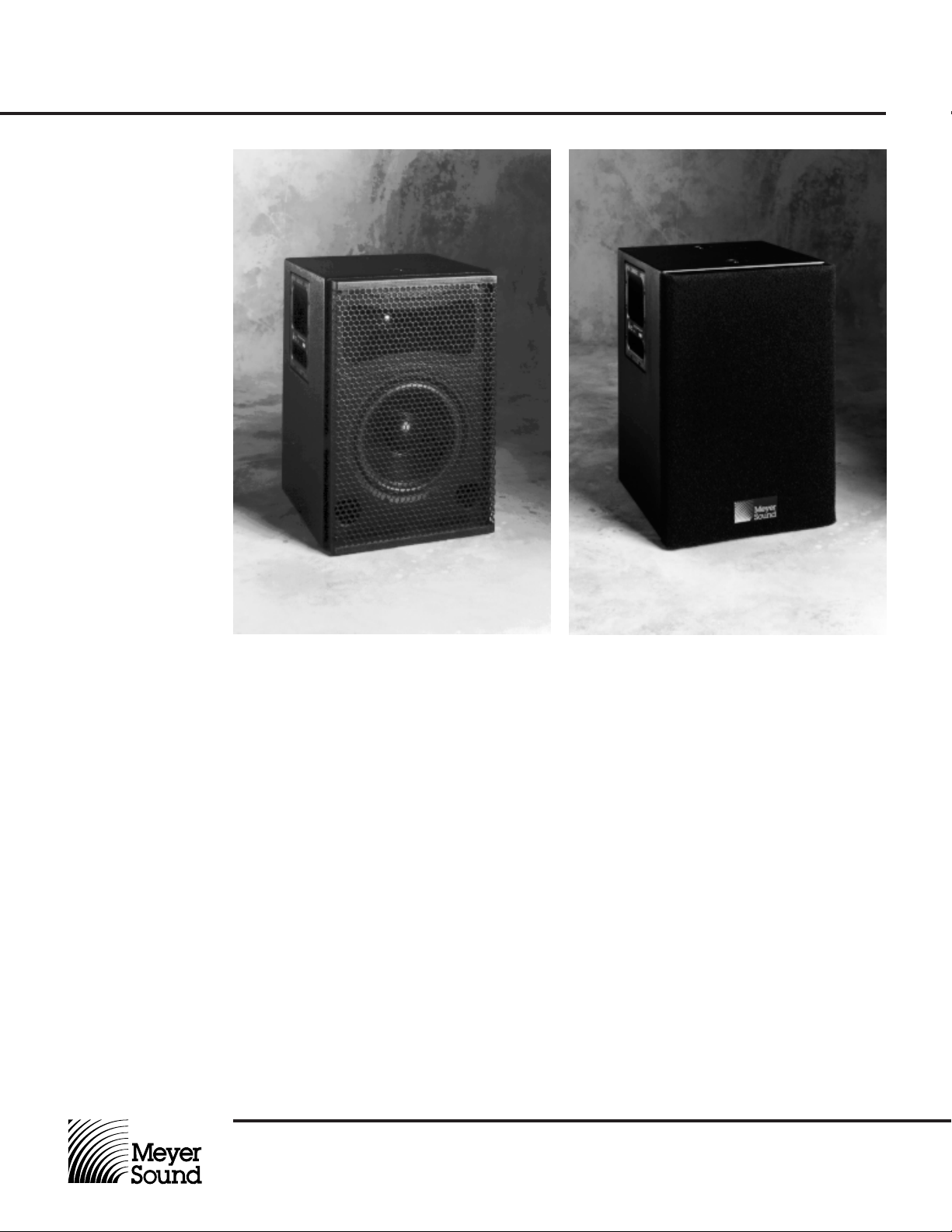
UPL-1 & UPL-2
High Definition
Reinforcement
Loudspeakers
The Meyer Sound
UPL-1 and UPL-2 are
self-contained, highdefinition, powered
loudspeakers suitable
for a wide variety of
high quality sound
reinforcement applications. The UPL-1
and UPL-2 incorporate line-level control
electronics mounted
within a rear panel
chassis, including:
• dual power
amplifiers for
biamplification
• an active balanced
input circuit with
switchable sensitivity (+4 dBu or
-10 dBV)
Operating Instructions
• an active crossover
utilizing optimized
pole-zero filter
combinations to
achieve acoustical
transparency and
linear phase
• independent protection circuits for
each loudspeaker
driver
The UPL-1 and UPL-2 are two-way systems
comprising a 10-inch cone low-frequency
driver and 1-inch high-frequency driver housed
in a vented cabinet. Both drivers are of a proprietary design, and are individually selected
for maximum linearity. The high-frequency
horn driver employs a titanium dome and silk
suspension in a patented, low distortion design
(US patent number 4,152,552). It is coupled to
° by 40° modified radial horn in the UPL-1,
a 90
and to a 60° aspherical waveguide in the UPL-2.
Aligned to closely approximate true point
source radiators within their coverage area,
the UPL-1 and UPL-2 feature tightly controlled
time delay response with minimal deviation
from linear phase across the full frequency
range of their operation. Each unit is individually factory-calibrated to ensure a free-field
frequency response that is flat within ±2 dB
from 50 Hz to 18 kHz. The UPL-1 and UPL-2
each deliver 124 dB peak SPL (1 meter) with
>100 dB dynamic range.
Meyer Sound Laboratories, Inc.
2832 San Pablo Avenue
Berkeley, CA 94702
Page 2

UPL-1 & UPL-2
High Definition
Reinforcement
Loudspeakers
Operating Instructions
Amplifiers and
Driver Protection
Power and Fuses
Connections
Independent power biamplifiers maximize system
headroom, efficiency and damping while minimizing distortion. The low frequency amplifier delivers
200 watts burst output power, while the high frequency amplifier provides 100 watts. Both employ
complementary power MOSFET output stages
operating class A at moderate listening levels
(<90 dB SPL), and class AB at high levels.
The UPL-1 and UPL-2 accept AC voltages from 90
to 260 VAC, at 50 or 60 Hz, in four ranges. Select
the range that is closest to the local mains voltage.
Do not switch among AC voltage ranges with the
power cable connected to an outlet. The UPL-1
and UPL-2 require a grounded outlet. Never cut
the earth ground pin or “float” the mains ground.
The UPL-1 and UPL-2 present a 10k ohm input
impedance at a three-pin XLR-type receptacle
wired as follows:
Pin 1 — Audio common
Pin 2 — Signal low (-)
Pin 3 — Signal high (+)
Case — Earth (AC) ground
Shorting any input connector pin to the case may
form a ground loop and cause hum. Standard
audio cables with XLR-type connectors may be
used for balanced signal sources. Unbalanced
sources will require an in-line adapter.
Where multiple UPL-1’s or UPL-2’s are driven from
a single source, it is best to “mult” at the source
output and run individual shielded cables to each
of the loudspeaker inputs.
The driver protection circuits employ thermo-predictive limiters and soft peak clamps to guard
against damage from excessive amplifier power
and ensure graceful overload characteristics.
Always set the voltage selector switch before connecting and operating the unit.
The unit is protected by a fast-acting fuse in the
voltage selector switch. If the fuse blows, check
the line voltage and voltage switch setting. Always
replace the fuse with the same type and rating.
Be certain that the source equipment is capable of
driving the total load impedance presented by the
paralleled loudspeaker input circuits. For example,
since the input impedance is 10k ohms, a source
output that can drive 600 ohms will handle a maximum of 16 UPL-1’s or UPL-2’s in parallel
(625 ohms total load impedance). If any of the
paralleled loudspeakers loses power, however, it
may cause distortion in some, or all, of the others.
The best solution for driving multiple units from one
source is to use individual, isolated outputs. This
can be accomplished, for example, by assigning
one channel of a CP-10 Complementary Phase
Parametric Equalizer to each loudspeaker and
branching the source output to the CP-10 inputs.
The system may then be aligned using SIM
tem II.
®
Sys-
Sensitivity Switch
Signal / Overload
Indicator
For professional balanced equipment, use the
+4 dBu setting. For semiprofessional and consumer unbalanced equipment, use the -10 dBV
setting. Driving the UPL-1 or UPL-2 from a +4 dBu
source with the switch set to -10 dBV will result in
increased noise.
Note that the -10 dBV setting is
In normal operation, the rear-panel LED will glow
green. At high listening levels, the LED may flash
red on program peaks. This indicates the onset of
overload, where the loudspeaker protection limiters
are activated.
Meyer Sound Laboratories, Inc.
2832 San Pablo Avenue
Berkeley, CA 94702
more sensitive
(designed for
setting:
• +4 dBu position:
1.23 VRMS = 114 dB SPL
• -10 dBV position:
0.316 VRMS = 114 dB SPL
If the LED is continuously red for an extended
period (8 hours or longer), thermal damage may
result.
lower
signal levels) than the +4 dBu
Page 3

UPL-1 & UPL-2
High Definition
Reinforcement
Loudspeakers
Operating Instructions
Installation
Calibration Port
Physical
Dimensions
The UPL-1 and UPL-2 are are aligned for flat frequency response in free field (no adjacent boundary surfaces). Placing either unit next to a wall or
floor will cause the low frequencies to be exaggerated, requiring equalization to correct. Always
allow at least 6 inches clearance behind the
speaker for cooling airflow.
3
The UPL-1 and UPL-2 are fitted with four
/8"-16
nut plates, two each on the enclosure top and
bottom. These may be used to attach the enclosures to cables for hanging, or to a suitable support plate for mounting on a loudspeaker stand.
Each rigging nut plate is designed to support the
weight of a single cabinet.
The calibration port is for factory use only. Do not
apply external voltages to any of the connector
pins.
Note. The UPL-1 and UPL-2 are not weatherresistant, and should not be installed outdoors
where they may be exposed to the elements.
To protect from hazard of shock and component failure, avoid rain or liquid spilled on the
amplifier chassis.
To avoid accidental disconnections, the UPL-1 and
UPL-2 cabinets are fitted with four tie-wrap anchors located at the four corners of the rearmounted amplifier chassis. Power and signal input
cables may be secured by inserting a plastic locking tie-wrap through any of these anchors, wrapping it around the cable(s) and locking it in place.
The UPL-1 and UPL-2 are not user-serviceable.
Refer service to an authorized Meyer Sound Service Center or to Meyer Sound.
8.88"
14.00"
20.75"
14.00"
UPL-2 UPL-1
20.75"
2.0"
9.20"
16.42"
15.54"
8.00"
13.20"
8.50"
14.00"
Meyer Sound Laboratories, Inc.
2832 San Pablo Avenue
Berkeley, CA 94702
Page 4

UPL-1 & UPL-2
High Definition
Reinforcement
Loudspeakers
Operating Instructions
Specifications
Acoustical
Frequency Response
Phase Response
Maximum SPL
Signal-to-Noise Ratio
Coverage Angle
Electrical
Input Type
Notes:
1. Subject to room loading.
Amplifier Type
Specified for 8 feet actual
distance between loudspeaker cabinet and a single
boundary surface, measured
with one-third octave fre-
Crossover
quency resolution in fixed
ISO bands.
Power
2. Specified with grill removed.
Response tolerance ±3 dB
with grill screen and foam in
place.
3. U.S. patent #5,185,801 (additional patent pending).
4. U.S. patent #4,152,552.
Unless otherwise specified, all
acoustical measurements are
Physical
Input Connector
Power Inlet
Driver Complement
Enclosure
Finish
Dimensions
performed at 1 meter from front
baffle on high-frequency horn
axis. Acoustical decibels are
specified re 20µPa.
Weight
Protective Grill
Rigging
1
UPL-1
UPL-2
Nominal Input Level
Power Output
Low Frequency
High Frequency
THD, IM, TIM
Low Frequency
High Frequency
1
±2 dB from 50 Hz to 18 kHz
2
-3 dB at 32 Hz and 20 kHz
+60°, -0° from 120 Hz to 18 kHz
124 dB peak @ 1 meter
> 100 dB
90° horizontal by 40° vertical
60° horizontal and vertical
Electronically balanced, 10k ohms impedance
Accepts either +4 dBu or -10 dBV, switchable
Complementary power MOSFET output stages
200 watts burst capability
100 watts burst capability
< .02 %
Optimized pole-zero filter combinations to complement
transducer response and to achieve acoustical transparency and flat phase
3
Voltage selector switch for 100/120/220/240 VAC, 50 or
60 Hz (accepts voltages from 90 to 260 VAC), 175 W
maximum
XLR (A-3) female
3-pin IEC male receptacle
10" diameter cone (2" voice coil)
1" titanium dome horn driver (1" voice coil)
4
1.6 cu. ft. vented, multi-ply Finnish birch
Black textured
14" W x 20 3⁄4" H x 14" D (+ 2 1⁄2" additional depth for
amplifier chassis and 2" for grill frame with foam)
70 lbs (32 kg)
Perforated metal screen, grey foam covering
3
/8"-16 nut plates, top and bottom
Maximum
Continuous SPL
by Frequency
16k
8k
4k
2k
1k
500
250
125
62
30
Frequency (Hz)
100 110 120
90
Continuous SPL (dB)
05.553.006.01 B © Meyer Sound, 1995.
Meyer Sound Laboratories, Inc.
2832 San Pablo Avenue
Berkeley, CA 94702
 Loading...