

Page 1
UM-1C
The UltraMonitor delivers the final
— 12
Features
High gain-before-feedback
Ultra-low distortion
Ultra-flat frequency response
Rugged and reliable
Applications
Stage Monitoring
Clubs and concerts
Low-throw coverage
Fill coverage
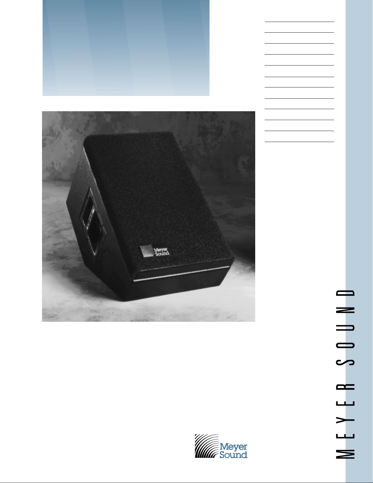
UltraMonitor™
–
–
— 9
–
–
— 6
–
–
— 3
–
–
— 0
Inches
word on high-powered, critical monitoring.
Specifically designed for touring reinforcement, the highly accurate, rugged UM-1C
biamplified system consists of a proprietary
12-inch low-frequency driver in a vented
enclosure, and a symmetrical pattern 45degree high-frequency horn with driver.
The UM-1C proprietary drivers provide
exceptional efficiency and power handling,
with ultra-low distortion for high clarity.
Very flat frequency response allows control
of feedback at high sound levels.
The sturdy, multi-ply hardwood enclosure with textured finish withstands road
abuse. The unit comes with handles and,
optionally, aircraft-style rigging pan fittings.
The UltraMonitor requires a highquality professional stereo power amplifier
capable of delivering up to 250 watts per
channel continuously into 8 ohms, with a
signal voltage gain of 20dB (minimum)
to 30dB (maximum).
Meyer Sound Laboratories, Inc.
2832 San Pablo Avenue
Berkeley, CA 94702
(510) 486-1166
FAX (510) 486-8356
Page 2

UM-1C Specifications
Acoustical – UM-1C/M-1A System
Frequency Response
Maximum SPL
1
2
with amplifier rated at: 250 W/8 ohms/ch. 60 W/8 ohms/ch.
70-18,000 Hz +4 dB
Continuous 125 dB 120 dB
Peak 135 dB 126 dB
HF Coverage, -6dB points 45 degrees symmetrical
UM-1C Loudspeaker
Transducers
Low Frequency MS-12 12-inch cone driver, 8 ohms
High Frequency MS-1401B 1.4-inch throat driver, 16 ohms
High-Frequency Horn 45 degree constant-directivity
HF Network Y-1PD
Function DC blocking and passive filters with alternate connection
terminal to adjust VHF response (16k peak or flat)
Enclosure 0.8 cu. ft. vented, multi-ply Finnish birch
Finish Black textured
Protective Grill Perforated steel screen, charcoal-grey foam covering
Connector Cannon EP-4 male, EP-5 male (Europe only)
Rigging (optional) Aircraft pan fittings or
Physical Dimensions 14" W x 14" H x 22
3
⁄8"-16 nut plates
1
⁄2" D
Weight 67 lbs. (30.4 kg)
M-1A Control Electronics Unit
Input Type Balanced (active), 47K ohms
Output Type Active push-pull, will drive 600 ohms
Maximum Input/Output Level
Balanced +26 dBu
Unbalanced +20 dBu
Hum and Noise
3
<-90 dBV
Dynamic Range 120 dB
Sense Inputs 10k ohms true differential, opto-isolated
Electronic Crossover Frequency 1600 Hz
Low-Frequency Delay Type Active all-pass
Driver Protection Circuitry
Low Frequency RMS limiter
High Frequency RMS limiter
VHF Peak limiter
Indicators
Sense, Hi and Lo Green LEDs
Limit, Hi, Lo, and VHF Red LEDs
Safe Green LEDs
Power Supply, Positive and Negative Green LEDs
Controls
Front Panel Input level control, AC on/off switch
Preset Panel VHF control, Lo Cut switch, Safe switch, VHF switch
Connectors
Balanced Inputs/Outputs 3-pin XLR (A-3), RTS
Subwoofer Circuit Input Unbalanced,
1
⁄4" phone jacks
1
⁄4" phone jack
(inserts Lo Cut, disables Level control)
Sense Inputs Banana jacks
Note 1:
Measured 1 meter on-axis,
half-space conditions,
pink noise input, in thirdoctave bands.
Note 2:
Loudspeaker driven with
weighted noise.
Note 3:
“A”- weighted, unbalanced.
Power 120/240V AC, 50/60 Hz (internally switchable)
Physical Dimensions 19" W x 1
3
⁄4" H x 73⁄4" D Standard rack mount
Weight 8 lbs. (3.6 kg)
Page 3

The M-1A Control
UltraSeries™ M-1A
Power
Sense Limit
Safe
Adj
Lo Cut
Cal
VHF
Var
Safe
∞
20
10
8
4
3
2
1
0
Attn dB
5
6
+ -
Lo
Hi
VHF
Electronics Unit
The UM-1C UltraMonitor operates as a
system with the M-1A Control Electronics Unit (one per channel). Optimized for
the UM-1C and UPA-1C loudspeakers
and pre-aligned at the factory, the M-1A
contains frequency response and phase
response alignment circuitry, and Meyer
Sound’s exclusive SpeakerSense™ driver
protection circuitry, incorporating both
peak and RMS signal limiting.
A single-channel device operating
at line level, the M-1A is the final component in the signal chain before the
amplifier.
SpeakerSense driver protection
circuitry protects the UM-1C loudspeaker
components from damage due to overheating under high power conditions.
This unique circuit continuously monitors the power applied to the UM-1C
drivers, and individually limits the highfrequency and low-frequency outputs
when the safe operating limits of the
drivers are exceeded. Until the onset of
overload, the SpeakerSense circuitry
has no effect on the signal.
Also provided is a switch-selectable
Safeguard function, which widens the
safety margin of the system and is intended to be used when extended periods
of overload are anticipated. The Safeguard switch and other setup controls
are located behind a cover plate on the
M-1A front panel, providing a means of
securing the system installer’s presets.
To enhance the effectiveness of the
UltraMonitor in stage monitoring applications, the M-1A incorporates sliding filters
which band-limit the system response
under full-power conditions. This has the
effect of discriminating for vocal information in the signal to increase clarity, and
is particularly useful when onstage levels
are high and leakage becomes a problem.
For this reason, it is recommended that
subwoofers be used with the system if it
must pass the full audio frequency range at
all times (as, for example, in keyboard
or drum monitors). The preferred choice
of subwoofer for the UltraMonitor is the
Meyer Sound USW-1.
Page 4

Architectural and
Engineering Specifications UM-1C/M-1A
Physical Dimensions
©1993 Meyer Sound 04051071.03A
7.5"
14.0"
7.5"
1"
2"
13.0"
15.0"
11.0"
14.44"
52
o
4.13"
22.38"
6.0"
2.2"
2.13"
Connector
(Recessed)
2.63"
18.5"
7.0"
3.18"
Meyer Sound Laboratories has
devoted itself to designing,
manufacturing and refining
components that deliver superb
The compact speaker system shall be
of the two-way type, with a 12" lowfrequency loudspeaker front-mounted in
a ducted bass-reflex hardwood plywood
enclosure, a compression driver
mounted on a high-frequency horn
which has a 1.4" throat, and a separate
Control Electronics Unit.
The Control Electronics Unit shall
contain a power supply capable of
operat-ing from a 120/240V AC, 50/60
Hz line, electronic crossover circuitry,
electronic delay for the phase alignment
of the low-frequency speaker, low- and
high-frequency protection filters which
automatically activate under high power
conditions, RMS limiters which protect
the speakers from overheating, equalization circuitry, active balanced input, and
indicator LEDs for power and limiters.
Total harmonic distortion shall be less
than .1%. “A”- weighted noise level shall
be at least 110dB below maximum rated
output of +26 dBu.
The speaker system, its companion
Control Electronics Unit, and a power
amplifier rated at 250 watts/channel into
8 ohms shall meet the following performance criteria: frequency response, 70 Hz to
18 kHz plus or minus 4 dB measured with
1/3 octave pink noise at 1 meter on axis;
output of 125 dB SPL one meter on axis
with peaks of 135dB SPL when driven with
“A”-weighted noise. Total mid-band harmonic distortion shall be less than 1% at
110 dB SPL and 3% at 120 dB SPL one
meter on axis. High frequency distribution
pattern, 45 degrees symmetrical.
Speaker enclosure dimensions are
14" W x 14" H x 221⁄2" D, weight 67 lbs
(30.4 kg).
Control Electronics Unit dimensions are
19" W x 13⁄4" H 73⁄4" D, weight 8 lbs (3.6 kg).
The speaker system shall be the Meyer
Sound UM-1C.
The Control Electronics Unit shall be
the Meyer Sound M-1A.
sonic reproduction. Every part of
every component is designed and
built to exacting specifications and
undergoes rigorous, comprehensive
testing in the laboratories.
Research remains an integral,
driving force behind all production.
Meyer strives for sound quality that
is predictable and neutral over an
extended lifetime and across an
extended range.
Sound
engineering
for the art
and science
of sound.
Meyer Sound Laboratories, Inc.
2832 San Pablo Avenue
Berkeley, CA 94702
(
510
) 486-1166
FAX (
510
) 486-8356
 Loading...