

Page 1
HARDWARE GUIDE COMPASS RMS
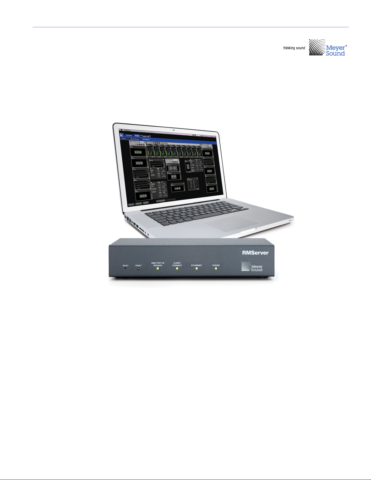
RMServer
Keep this important user guide.
Check www.meyersound.com for updates.
Page 2

© 2014
Meyer Sound Laboratories, Inc. All rights reserved.
Compass RMServer/Remote Monitoring System Hardware Guide, PN 05.222.024.01 A
The contents of this manual are furnished for informational purposes only, are subject to change without notice, and should not be construed as a commitment by Meyer Sound Laboratories Inc. Meyer Sound assumes no responsibility or liability for any errors or inaccuracies that may appear in this manual. Except as permitted by applicable copyright law, no part of this publication may be reproduced,
stored in a retrieval system, or transmitted, in any form or by any means, electronic, mechanical, recording or otherwise, without prior written permission from Meyer Sound.
MEYER SOUND and the Meyer Sound wave logo are trademarks of Meyer Sound Laboratories Inc. and are registered in the United States
Patent and Trademark Office, as well as in other countries.
The following is a partial list of additional Meyer Sound trademarks and service marks:
650-P*, 650-R2*, Acheron*, AlignALink, BroadbandQ*, CAL, Callisto, Compass*, Compass RMS, Composite EQ, Constellation*, CueConsole, CueStation, D-Mitri*, EXP*, Galileo*, GuideALink, Intelligent AC, LCS, LEO, LEO-M, M Series, M1D, M2D, M3D, MAPP Online Pro*,
Matrix3, MatrixLink, M'elodie*, Meyer Sound MAPP Online, MICA*, MILO*, MINA, MSL-4*, MultiSense, QuickFly*, QuietCool, REM*, RMS,
RMServer, SIM*, SpaceMap*, SpeakerSense, Stella, Thinking Sound*, TM Array, TruPower*, TruShaping*, UltraSeries, U-Shaping*, VariO,
VRAS, Wild Tracks.
All third-party trademarks mentioned herein are the property of their respective trademark holders.
*Registered in the United States Patent and Trademark Offices
ii
Page 3

CONTENTS
Chapter 1: Introduction 5
How to Use This Manual 5
The Compass RMS Remote Monitoring System 5
Workflow for Compass RMS Configurations 7
Chapter 2: Installing and Configuring RMServer 9
About RMServer 9
RMServer Features and Functions 9
Installation and Mounting 10
Setting Up an RMS Network with RMServer 10
Connecting RMServer 10
Configuring the RMServer Web Server 12
Chapter 3: Connecting RMS Networks 21
Network Specifications 21
Twisted-Pair Cabling 21
Ethernet Hubs and Switches 22
Design Tips for RMS networks 23
Ethernet Configurations 24
Chapter 4: HP/MP RMS Module 29
Installing the HP/MP RMS Module 29
Installing the Mute Jumper on the HP/MP RMS Module 33
HP/MP RMS User Panel 34
Neuron ID for HP/MP RMS Modules 34
Resetting the HP/MP RMS Module 35
Chapter 5: UltraSeries RMS Module 37
Installing the UltraSeries RMS Module 37
Installing the Mute Jumper on the UltraSeries RMS Module 38
UltraSeries RMS User Panel 39
Neuron ID for UltraSeries RMS Modules 40
Resetting the UltraSeries RMS Module 40
Chapter 6: DX RMS Module 41
Installing the DX RMS Module 41
DX RMS User Panel 41
Neuron ID for DX RMS Modules 42
Resetting the DX RMS Module 42
Chapter 7: MX RMS Module 43
Installing the MX RMS Module 43
Installing the Mute Jumper on the MX RMS Module 45
MX RMS User Panel 46
Neuron ID for MX RMS Modules 46
Resetting the MX RMS Module 46
iii
Page 4

CONTENTS
Chapter 8: LYON RMS Module 49
Installing the LYON RMS Module 49
Lyon RMS User Panel 50
Neuron ID for Lyon RMS Modules 51
Resetting the Lyon RMS Module 51
Chapter 9: MPS-488HP External Power Supply with RMS 53
MPS-488HP RMS User Panel 53
Neuron ID for MPS-488HP RMS Module 54
Resetting the MPS-488HP RMS Module 54
The MPS-488HP in Compass Software 54
Appendix A: Comparison of RMS Modules 55
Appendix B: Troubleshooting RMS Problems 57
Appendix C: External Muting and External Warning Relays 61
Wiring RMServer for External Muting and External Warning Relays 62
Configuring External Muting in the RMServer Web server 63
Configuring Warning Relays in the RMServer Web Server 64
Email Notification for Externally Triggered Muting and Warning Relays 65
Appendix D: FTR-120 Free Topology Repeater 67
About the FTR-120 67
Installing and Using the FTR-120 67
RMS Configuration Sheet 69
70
iv
Page 5
CHAPTER 1: INTRODUCTION
This introductory chapter includes the following topics:
■ “How to Use This Manual” on page 5
■ “The Compass RMS Remote Monitoring System” on
page 5
■ “Workflow for Compass RMS Configurations” on page 7
HOW TO USE THIS MANUAL
Make sure to read this user guide in its entirety before configuring a Compass RMS™ system. In particular, pay close
attention to material related to safety issues.
As you read this user guide, you will encounter the following
icons for notes, tips, and cautions:
NOTE: A note identifies an important or useful
piece of information relating to the topic under
discussion.
TIP: A tip offers a helpful tip relevant to the topic
at hand.
CAUTION: A caution gives notice that an
action may have serious consequences and
could cause harm to equipment or personnel, or
could cause delays or other problems.
[Default Values] are bracketed and are displayed in type-
writer (monospace) font.
Information and specifications are subject to change.
Updates and supplementary information are available at
www.meyersound.com
■ Compass RMS product page.
■ RMS product page.
■ Webinars and Product Tutorials areas of the Education
page.
■ Sound Support page.
Meyer Sound Technical Support is available at:
■ Te l: +1 510 486.1166
■ Web: www.meyersound.com/support
■ Email: techsupport@meyersound.com
.Some places to check are:
THE COMPASS RMS REMOTE MONITORING SYSTEM
NOTE: In this manual, both RMS-equipped
loudspeakers and MPS-488HP power supplies
are generically referred to as "devices."
The Compass RMS remote monitoring system provides
extensive real-time displays on a Windows or Mac OS X
computer of status and performance data for each loudspeaker in a system, including amplifier voltage, limiting
activity, power output, and fan and driver status. Soloing
and muting of each loudspeaker is also available. Compass
RMS consists of:
■ RMS module: Each loudspeaker in an RMS network has
an RMS module installed in it, which monitors parameters like limiting, fan speed, heat sink temperature, and
amplifier power, and reports that information back to the
Compass control software. The RMS module stores the
type of loudspeaker in which it is installed, a loudspeaker
ID, and a user-assigned name. Some Meyer Sound loudspeakers come standard with an RMS module installed
while others offer it as an option. For more information,
visit the Meyer Sound website.
■ RMServer: Loudspeakers and other devices on an RMS
network are connected to a computer running Compass
software through RMServer hardware. Up to 50 loudspeakers or 12 MPS-488HP power supplies can be
attached to each RMServer. RMServer replaces all iLON
hardware used in legacy systems; iLON hardware is
incompatible with Compass-based RMS networks.
■ Compass control software: Provides an integrated envi-
ronment for controlling and monitoring loudspeaker systems. Compass uses a graphical user interface running
on a remote computer to display information provided by
the Compass RMS remote monitoring system, and provide comprehensive control of CAL column array loudspeakers, Galileo loudspeaker management processors,
and Callisto array processors.
Compass software includes a context-sensitive help system, and full copy and paste of all settings and groups of
settings. The tabbed interface can be scaled to any display
resolution and the color scheme or contrast can be configured for either day or night. Windows and Mac OS X versions have the same user interface, so switching between
platforms is completely transparent.
■ After Hours Emergencies: +1 510 486.0657
5
Page 6
CHAPTER 1: INTRODUCTION
TIP: For information on installing and using
Compass control software, see the Quick Start
Guide on the Compass RMS product page at
www.meyersound.com
.
Compass RMS incorporates an established network platform developed by Echelon Corporation, the world’s leading
supplier of networking technology for sensing, monitoring,
and control. The networking platform supports Free Topology, is polarity insensitive, does not require coaxial or fiber
optic cabling, and is not affected by power losses at loudspeaker nodes. An RMS network is a real-time data acquisition system, which means that no data is lost during
transmission.
Once loudspeakers are identified on the RMS network, they
appear in the Compass software as icons or meter views
with pop-up text displays; they are automatically added to
the RMServer inventory and Compass Project.
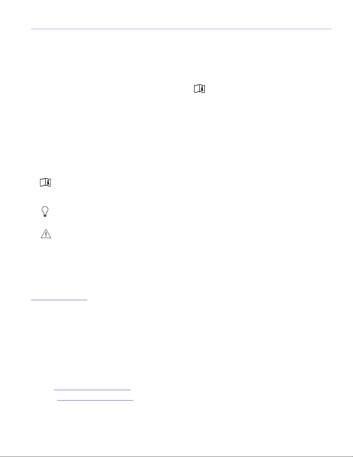
Figure 2: A user-created page under the RMS tab in Compass.
Compass RMS Software System Requirements
Compass RMS software runs as a tab within the Compass
software environment. Compass requires a computer run-
®
ning Windows
sound.com for the latest compatibility information and more
information about Compass.
or Mac OS X. Please visit www.meyer-
Figure 1: Some RMS objects as they appear on user pages.
Compass displays all loudspeakers on the network on usercreated pages under the RMS tab. Pages display icons and
meter views that you customize to suit your needs. Loudspeaker icons and meter views can be arranged to represent
how the loudspeakers have been deployed in the system.
Multiple pages can be created for specific system configurations and venues, saved as an RMS Project, and reloaded
as needed.
Loudspeaker data is updated 2-5 times per second. Individual loudspeakers can be physically identified with the Wink
option in Compass, which lights the Wink LED on the RMS
module for that particular loudspeaker. Conversely, a device
can be in identified in Compass by pressing the Identity or
Service button on the device’s RMS module.
Additional Networking Hardware Requirements
Depending on the number of loudspeakers in the RMS network, as well as the length of cabling used, additional networking hardware — such as repeaters, terminators,
switches, or hubs — may be required. In some cases, multiple RMServers may be recommended. For more information, see Chapter 3, “Connecting RMS Networks.”
6
Page 7

RMS USER GUIDE
WORKFLOW FOR COMPASS RMS CONFIGURATIONS
To configure a Compass RMS system, use the following
steps:
1. Prepare any retrofitted or legacy equipment for integration into a Compass RMS system. For more information,
see the next section, “Upgrading, Retrofitting, and Legacy Loudspeakers” on page 7
2. Install RMServer as described in the section “Installation
and Mounting” on page 10
3. Attach RMServer to the computer’s Ethernet port or to a
network router or network switch as described in the
section “Remote Computer Connection” on page 10
4. Connect RMServer to your RMS-equipped devices as
described in the sections “Connecting RMServer to Your
RMS-Equipped Loudspeakers” and “Connecting
RMServer to the MPS-488HP” on page 11
5. Configure network settings on RMServer and your computer. as described in the section “Configuring the
RMServer Web Server” on page 12
6. Install the Compass control software. For more information, see the Quick Start Guide on the Compass RMS
product page at www.meyersound.com
.
7. Launch and configure the Compass control software. For
more information, see the Quick Start Guide on the Compass RMS product page at www.meyersound.com
.
Upgrading, Retrofitting, and Legacy Loudspeakers
Additional steps in setting up a Compass RMS system are
required if:
To facilitate manual initialization, be sure to make a list of the
models and Neuron IDs of all loudspeakers other than those
built after June 2012. The Neuron ID is displayed on each
loudspeaker’s RMS user panel. You can use the datasheet
on page 69 of this user guide for creating a list of loudspeakers in the setup For more information see the section
“Setting IDs for legacy RMS cards” in the Quick Start Guide
available on the Compass RMS product page at www.mey-
ersound.com.
Transitioning from a Legacy iLON System
Upgrading from a legacy, iLON-based system to a Compass-based RMS network is not difficult. The main difference, of course, is the substitution of RMServer units for
iLON 10 Ethernet adapters and iLON 600 servers. However,
there are a few important things to note:
■ You MUST disconnect the host station hardware and
remove it entirely from the network; it is incompatible
with Compass RMS. This includes removing U10 USB
connectors, iLON 10 Ethernet adapters, and iLON 600
servers.
■ In distributed systems and some other situations, a leg-
acy iLON system may have been configured with small
groups of loudspeakers attached to individual iLON
hardware units. Smaller groups can be consolidated in a
Compass RMS system, up to RMServer's maximum of
50 loudspeaker nodes.
■ Reverting back to an iLON-based RMS system after
upgrading to a Compass-based RMS network is not recommended, but it is possible to do simply by restoring
the iLON hardware in place of RMServer, and using the
old RMS software instead of Compass. However, doing
this is likely to require rediscovering the entire system.
■ You are transitioning from a legacy iLON-based RMS
system.
■ You are retrofitting any Meyer Sound loudspeakers with
RMS modules.
■ You are using Meyer Sound loudspeakers that contain
RMS modules but were built prior to June 2012. This
usually will be the case if you are transitioning from an
iLON-based RMS system.
It is always the case in these last two situations, and usually
the case when transitioning from an iLON-based system,
that each loudspeaker must be manually initialized with its
loudspeaker ID information. Loudspeakers built after June
2012 with RMS modules installed are initialized at the factory.
NOTE: Some products are not supported by
legacy RMS software and iLON-based sys-
tems.
Retrofitting Loudspeakers with RMS Modules
Information on installing RMS modules into Meyer Sound
loudspeakers that did not come with them can be found
elsewhere in this manual:
■ For loudspeakers requiring an HP/MP RMS module, see
“Installing the HP/MP RMS Module” on page 29. To
enable mute and solo capabilities in these loudspeakers,
see “Installing the Mute Jumper on the HP/MP RMS
Module” on page 33.
7
Page 8

CHAPTER 1: INTRODUCTION
■ For loudspeakers requiring an UltraSeries RMS module,
see “Installing the UltraSeries RMS Module” on page 37.
To enable mute and solo capabilities in these loudspeakers, see “Installing the Mute Jumper on the UltraSeries
RMS Module” on page 38.
■ For loudspeakers requiring a DX RMS module, see
“Installing the DX RMS Module” on page 41. To enable
mute and solo capabilities in these loudspeakers, see
“Remote Mute Switch” on page 42
8
Page 9
CHAPTER 2: INSTALLING AND CONFIGURING RMSERVER
ABOUT RMSERVER
RMServer is the central hardware component of a Compass
RMS remote monitoring system. RMServer is a compact
server that connects up to 50 RMS-equipped loudspeakers
or 12 MPS-488HP power supplies to a computer running
Compass control software. (Each MPS-488HP can drive up
to eight loudspeakers for a total of 96 loudspeakers on a
single RMServer.)
RMSERVER FEATURES AND FUNCTIONS
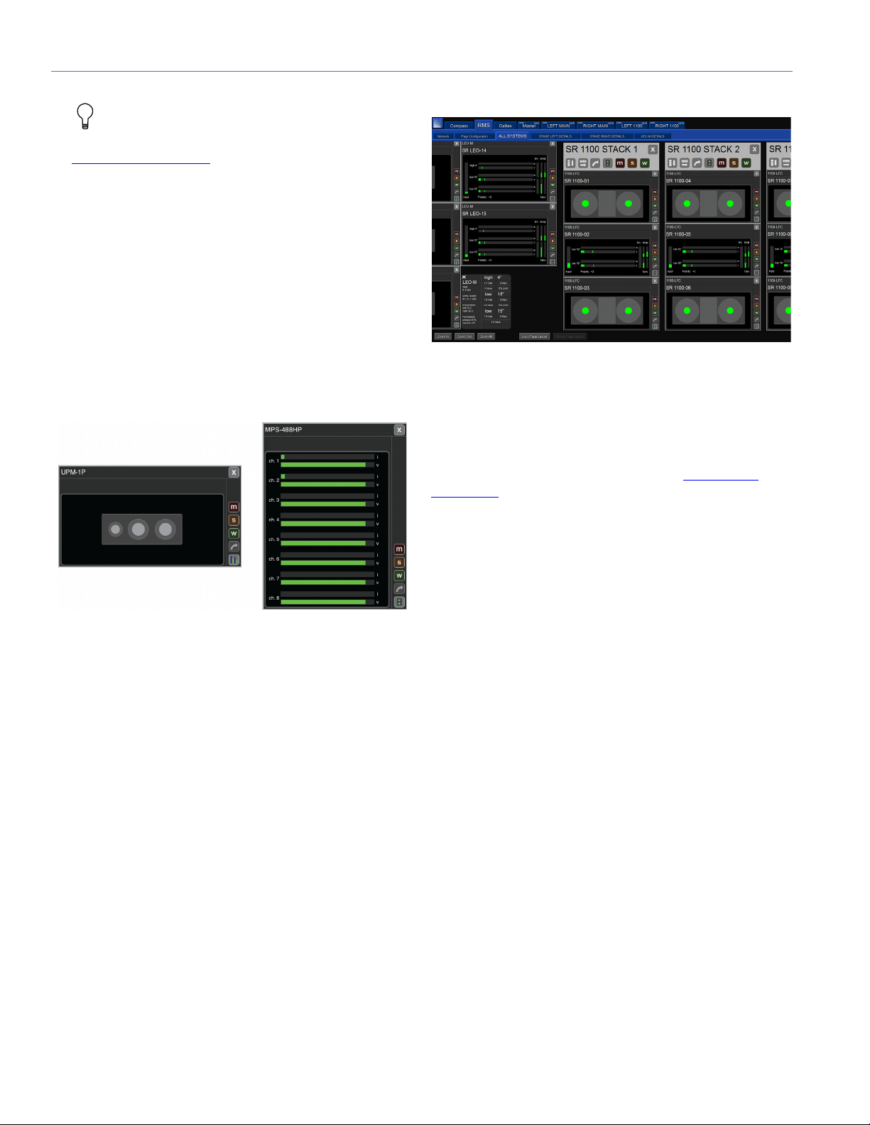
RMServer Front Panel
Figure 1: The RMServer front panel
The RMServer front panel contains a Reset button and a
number of indicators.
Reset button: Pressing the Reset button restarts RMServer.
There are several reset modes invoked by different kinds of
button presses. For more information on restarting
RMServer, see the section“Restarting RMServer” on
page 18.
Fault indicator: Indicates loudspeaker faults and abnormal
operating conditions. The Fault indicator is also used to
show when RMServer is running in failsafe mode. For more
information on when to use failsafe mode see the section
“RMServer Failsafe (Recovery) Mode” on page 18.
RMS TP/FT10 Receive LED: Indicates that RMServer is
receiving messages from a device.
Client Connect LED: Indicates that RMServer is failsafeconnected to a client computer running Compass control
software.
Ethernet LED: Indicates Ethernet activity when RMServer is
connected to a computer running Compass control software.
AC Power LED: Indicates when RMServer is receiving AC
power.
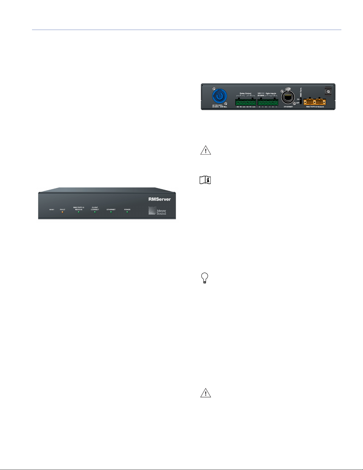
RMServer Rear Panel
Figure 2: The RMServer rear panel.
PowerCon AC Power Connector: This locking connector
mates with the provided AC power cable.
CAUTION: Make sure the AC power cable has
the appropriate power plug (on the other end)
for the area in which you will operate RMServer.
NOTE: RMServer incorporates Meyer Sound’s
Intelligent AC power supply, which automatically adjusts for any line voltage between 90 and 264
volts, and provides both soft turn-on and transient
protection.
Relay Outputs: Alert conditions can be signaled to external
devices by changing the state of two onboard relays.
+12V Output: Provides voltage for outboard contact closure
relays connected to RMServer's opto-isolated inputs, such
as those used in fire alarm or other emergency systems to
trigger loudspeaker muting.
TIP: For more information about connecting
relays to RMServer's inputs, see the sec-
tion“Connecting RMServer” on page 10.
Opto-Inputs 1 and 2: For installations where RMServer is
part of a fire alarm or evacuation system, the active audio
inputs (main program sources) of all devices connected to
that RMServer can be muted using these opto-isolated
inputs. The mute can be triggered with a relay closure
attached to the Opto Input pins. Each pin is triggered when
it receives a voltage 3 to 20 VDC greater than its associated
COM pin. The source of this voltage is commonly the +12 V
output. When triggered, the isolated opto input instructs
RMServer to mute all Mute Enabled connected loudspeakers.
CAUTION: Do not send voltages greater than
20 V DC to the Logic I/O pins as this may damage the input circuitry.
9
Page 10

CHAPTER 2: INSTALLING AND CONFIGURING RMSERVER
NOTE: The logic I/O connectors (Relay out-
puts, +12 V, Inputs 1 and 2) are optically isolated from the RMServer circuitry. In addition, each
COM pin is isolated to allow for the use of appropriate reference voltages for each associated logic function. A logic function is triggered when the + pin on
the connector receives a voltage 3 to 20 V DC greater
than its associated COM voltage.
Ethernet Connector: RJ-45 connector for connecting
RMServer to an Ethernet network, so it can be controlled
from a computer running Compass control software. Use a
shielded CAT-5e cable (recommended) or high-quality Ethernet data cable.
RMS termination switch: RMServer is capable of providing
standard 52.3 ohm network termination.
■ To engage network termination on RMServer, use a
paper clip, screwdriver, or similar small implement to flip
the RMS Term switch to the On position.
RMS TP/FT10 Network connectors: The two Weidmuller
connectors transfer data to and from the RMS network. Two
connectors are provided to allow for easy connection of
multiple daisy-chained loudspeakers on the network. RMS
cable connectors and mounting blocks for constructing
RMS cables are included with each RMS-equipped loudspeaker. The RMS blocks allow the cables to be securely
attached to the RMS module with screws.
SETTING UP AN RMS NETWORK WITH RMSERVER
To connect RMServer into your system and set up an RMS
network:
1. Attach RMServer to the computer’s Ethernet port or to a
network router or network switch.
2. Connect RMServer to your RMS-equipped devices.
3. Configure network settings on RMServer and your computer. For more information see the section “Configuring
the RMServer Web Server” on page 12.
4. Install the Compass control software.
5. Launch and configure the Compass control software.
CONNECTING RMSERVER
Power Connector
RMServer uses a locking PowerCon® connector to provide
AC voltage to the unit. Its internal switching power supply
accepts voltages from 90 to 264 V AC, 50/60 Hz.
CAUTION: Electrical Safety Issues! Pay close
attention to these important electrical and
safety issues:
RMServer MAC address: The ID displayed on the barcoded sticker on the rear panel is the MAC address of the
RMServer unit, which is displayed on the Network page of
the RMS tab in Compass software. (A MAC, or Media
Access Control, address is a unique identifier for a network
interface.)
INSTALLATION AND MOUNTING
Rackmount (Meyer Sound Part Number: 40.222.015.01) and
wallmount (Meyer Sound Part Number: 04.222.014.01) kits
are available for RMServer. Two RMServers can be installed
in one rackmount shelf.
For more information on mounting kits for RMServer, contact Meyer Sound.
An integral tie-wrap anchor (width: 0.176 in/4.47 mm) on the
rear panel enables strain relief for power and signal cables
attached to RMServer. Insert a plastic tie-wrap through the
anchor and wrap it around the cables.
■ Make sure the AC power cable has the appropriate
power plug (on the other end) for the area in which you
will operate RMServer.
■ Always use a grounded outlet and plug.
CAUTION: To comply with EMC standards,
only operate this device with the supplied
shielded power cord.
Remote Computer Connection
RMServer's RJ-45 port connects to a standard Ethernet port
with a shielded Cat-5e or Cat-6 cable. The Ethernet connection allows the unit to be controlled remotely from a Mac or
Windows computer running Compass control software.
RMServer can operate on the same network as Galileo processors and other Meyer Sound network devices.
10
Page 11

RMS USER GUIDE
IPv4, IPv6, and RMServer
The internet is currently near the beginning of a migration
from the IPv4 protocol it has used for years to the newer
IPv6 protocol. IPv4 uses a 32-bit address for each machine,
and unique addresses are running out. IPv6 uses 128-bit
addresses, commonly incorporating each computer’s fixed
Media Access Control (MAC) address.
This will be a long, slow transitional period, in which it will be
common for all systems employing IP to contain a mix of
systems capable of IPv4, IPv6, or both. Currently, it is easier
to use IPv6 in Mac OSX than in Windows, though Windows
is technically capable of it.
TIP: The settings in the Host and Network Infor-
mation section of RMServer web server's Basic
Settings tab pertain only to the use of IPv4. However,
for the most reliable flexibility in operation, Meyer
Sound recommends filling out all of the fields in the
Host and Network Information section, even if you do
not anticipate your network will need to use IPv4. For
more information on the Host and Network Information section, see the section “Configuring the
RMServer Web Server” on page 12.
NOTE: RMServer ships from the factory set to
a default static IPv4 address. In order to
change the IPv4 address, it is necessary to access
RMServer's web server page. For more information
on setting RMServer's IPv4 address, see the section
“Accessing the RMServer Web Server” on page 12.
The Bonjour and host name methods listed there
eliminate the use of IPv4.
Connecting RMServer to Your RMS-Equipped Loudspeakers
RMServer connects to RMS-equipped loudspeakers
through 20 AWG twisted pair, stranded, unshielded cable
(Belden 8205 or equivalent). To reduce the amount of
twisted-pair cabling in an RMS network, groups of neighboring loudspeakers can be daisy-chained.
For twisted-pair cabling, the following limitations apply:
■ Maximum number of RMS nodes: 50
■ Maximum number of MPS-488HP power supplies: 12
■ Maximum length of total cabling: 1640 ft (500 m). An
FTR-120 repeater can be used for cable runs longer than
500 m.
RMS-equipped loudspeakers and MPS-488HP power supplies can be mixed on a single RMServer (which has two
paralleled network connectors), as long as the total number
of loudspeakers does not exceed 50. Note that each MPS488HP counts as four loudspeakers for this purpose, even
though the power supply can drive up to eight loudspeakers. For example, you could connect five MPS-488HP units
(counting as 20 loudspeakers) and 30 RMS-equipped loudspeakers to a single RMServer.
TIP: For more information on connecting loud-
speakers in an RMS network, see Chapter 3,
“Connecting RMS Networks”.
Connecting RMServer directly to your computer
If you are using only a single RMServer unit and no Galileo
or other Meyer Sound device, you can connect it directly to
your computer's Ethernet port. This is the simplest possible
connection. If you are using IPv4, your computer and
RMServer must be set to the same IPv4 network range to
communicate.
Connecting RMServer to a network switch
Larger systems requiring more than one RMServer or that
include Galileo processors or other Meyer Sound devices
will connect to your computer through a network switch.
NOTE: When connecting an RMServer to a
computer through a router, make sure the
router is appropriately configured.
Connecting RMServer to the MPS-488HP
Figure 3: The rear panel of an MPS-488HP power supply includes the
same Weidmuller connectors found on RMS modules in loudspeakers.
RMServer is connected to an MPS-488HP power supply in
the same fashion as it is connected to RMS-equipped loudspeakers, via the Weidmuller connectors on the MPS488HP. Loudspeakers connected to an MPS-488HP differ
from Meyer Sound self-powered loudspeakers in that they
are powered by 48 VDC from the MPS-488HP, rather than
receiving AC power directly. Also, as mentioned above, for
the purposes of the loudspeaker inventory count, each
MPS-488HP must be counted as four loudspeakers.
11
Page 12
CHAPTER 2: INSTALLING AND CONFIGURING RMSERVER
TIP: For more information on integrating an
MPS-488HP into an RMS network, see
Chapter 3, “Connecting RMS Networks”.
RMServer Inventory
Under the control of Compass control software RMServer
compiles an inventory of all devices connected. In addition
to being displayed in Compass, this inventory is automatically saved in non-volatile memory onboard the RMServer
and loaded by default each time RMServer is powered up.
The inventory is retained unchanged until modified by the
user from within Compass.
Connecting Relays
In many sound systems it is necessary to have the ability to
mute all loudspeakers in an emergency or failure condition.
This function is usually triggered by a simple relay action.
RMServer's two inputs accommodate triggering of loudspeaker muting from external relays. Triggering of external
systems is supported by two onboard relays that fire under
conditions set in RMServer's web server pages. RMServer's
onboard relays can be wired to operate either as Normally
Open (NO) or Normally Closed (NC).
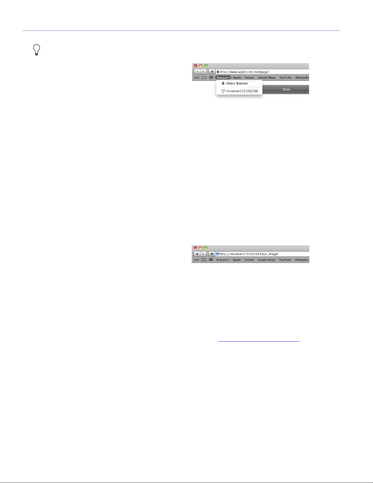
As a Bonjour Client (Safari only)
Figure 4: In Safari running in Mac OS X, Bonjour provides an easy
method of communicating to RMServer using IPv6.
Apple's Bonjour protocol supports IPv6 in Mac OS X, but
only IPv4 in Windows.
1. In Safari, open Safari Preferences and go to the Bookmarks tab.
2. In the Bookmarks bar section, click the Include Bonjour
check box to select it. Close the Preferences dialog.
3. Click on the Bonjour link on the left of the Bookmarks
bar. A menu will drop down.
4. Choose RMServer from the menu. It is identified in the
list with its host name and device name. The login page
will appear.
Using RMServer's Host Name
For more information on wiring and configuring RMServer
for use with fire alarm muting systems, see Appendix C,
“External Muting and External Warning Relays”
CONFIGURING THE RMSERVER WEB SERVER
Accessing the RMServer Web Server
The RMServer web server can be accessed in two different
ways: from Compass or using a browser.
The default user name and password for login are both
"admin".
RMServer can be accessed from Compass if it has already
been configured, has already been found by Compass, and
is displayed in the device list on the Network page:
■ Right-click on the device name of the server in the list
and choose Access Web Server from the menu that
drops down to open the web server login window.
The other way to access the web server is using a standard
browser. Meyer Sound recommends using Google Chrome,
Mozilla Firefox, or Apple Safari to communicate with
RMServer. There are three methods for accessing the web
server from a browser:
Figure 5: RMServer can be reached from any browser by using its host
name.
Communication with RMServer by its host name is accomplished using IPv6.
1. Open a browser.
2. In the URL address line, enter: rmserver<serial number>.local, where <serial number> is the serial number of
the RMServer unit, found on a sticker on the rear panel,
for example: http://rmserver213020341.local
. The web
server login page will appear.
Using RMServer's IPv4 Address
Meyer Sound recommends accessing RMServer using IPv6
whenever possible, however, users with Windows machines
or legacy equipment may need to continue using IPv4 to
access RMServer. The default IPv4 address of RMServer is
192.168.0.120.
1. If your network is already set to the 192.168.0.x network
range, you should skip step 3.
12
Page 13
RMS USER GUIDE
2. Connect your computer's Ethernet directly to RMServer.
3. Set your computer to a static IP address in the network
range 192.168.0.x.
4. Open your browser and point it to 192.168.0.120, the
default address of RMServer. The login page will appear.
TIP: If any of these methods appears to hang
up, try clicking in the URL address bar of the
browser and pressing Enter to reapply the URL
request.
Setting an IPv4 Address for RMServer
4. In the Network Information area, change the Static IP
Address field to an address with the network range you
want to use.
5. Enter the proper Subnet Mask and Gateway settings.
The default subnet mask is 255.255.255.0, the default
gateway address is 192.168.0.1.
6. Click the Save Settings button at the bottom of the window.
7. A dialog will appear saying that restart is required. Click
the Restart Now button to restart RMServer.
8. Change your computer (and router, if present) IP address
to the same network range as RMServer.
9. Test the connection by pinging RMServer with the ping
command in a terminal.
Settings
The Dashboard tab displays current settings. Settings are
adjusted in the Basic and Advanced Settings tabs.
Settings groups on the Basic and Advanced Settings pages
can be expanded or collapsed by clicking on the disclosure
triangle to the left of the settings group name.
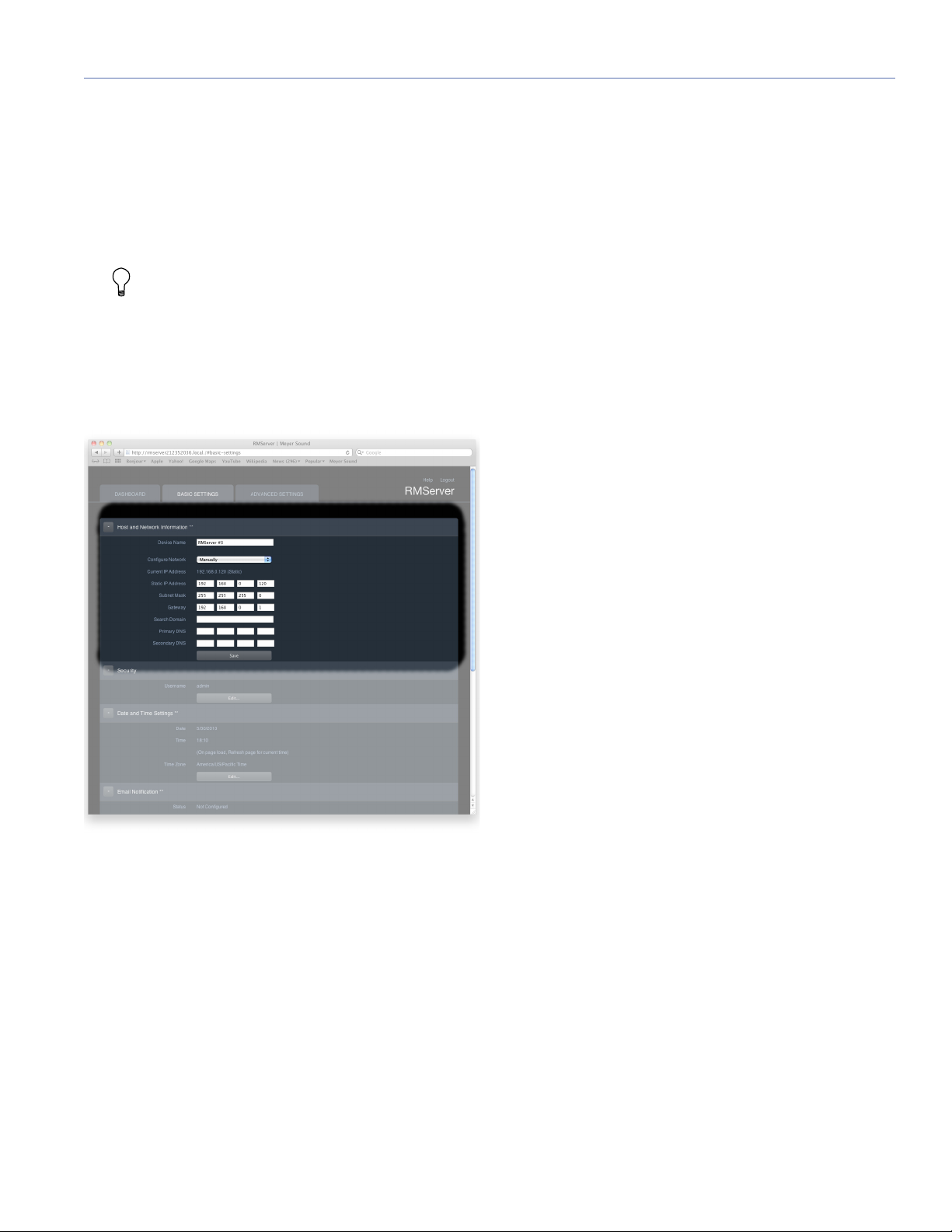
Figure 6: The Host and Network Information area of the Basic Settings
tab holds IPv4 settings.
In order for users employing IPv4 to communicate with
RMServer, the computer, router, and RMServer all need to
be set to the same IP network range. To set RMServer's
IPv4 address:
1. Login to RMServer's web server page.
2. Go to the Basic Settings tab.
3. In the Network Information area, confirm that the Configure field is set to Manually.
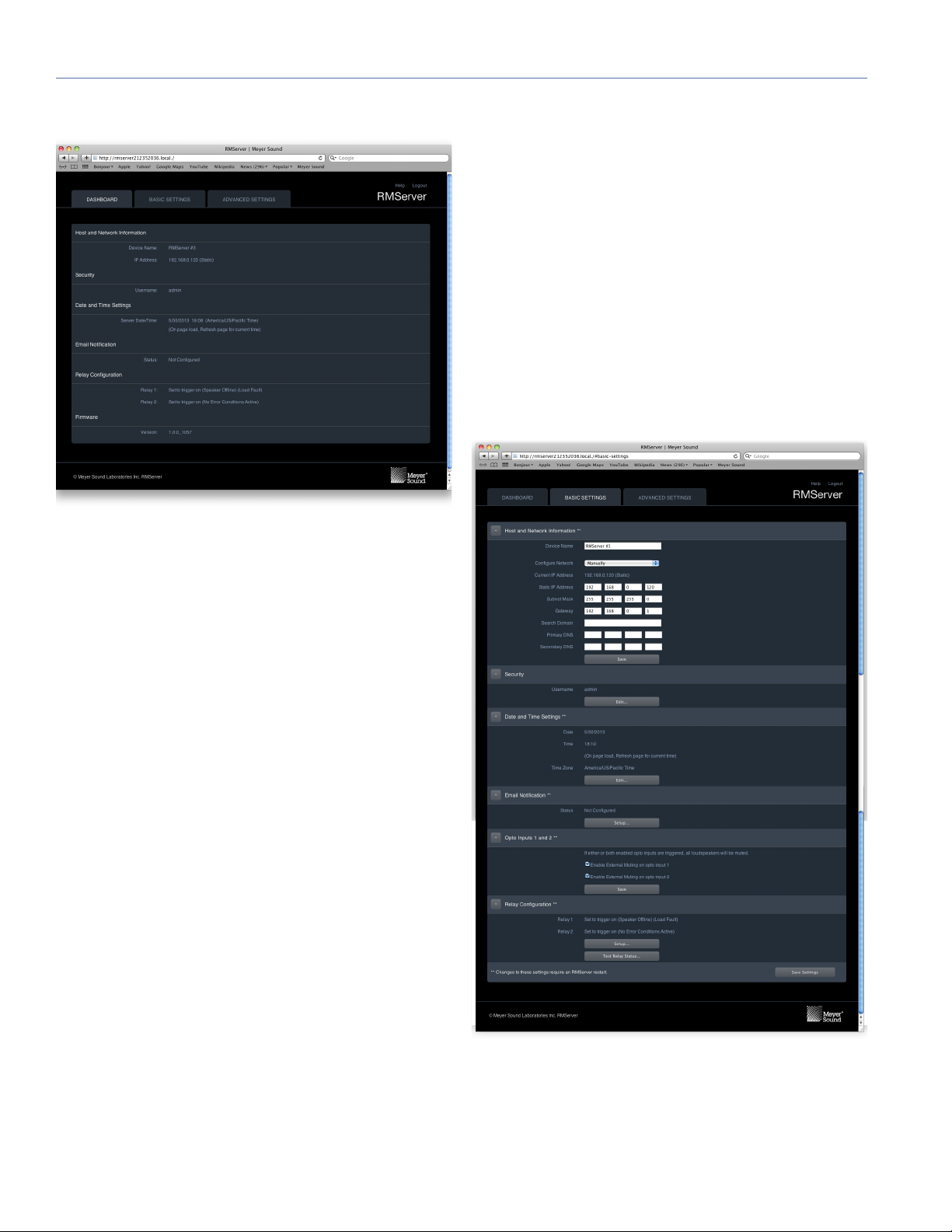
Dashboard
The Dashboard tab displays setup parameters for
RMServer, but editing of parameters is done on the Basic
and Advanced Settings pages.
13
Page 14
CHAPTER 2: INSTALLING AND CONFIGURING RMSERVER
Relay Configuration
Displays the fault conditions that trigger RMServer to
change the state of the indicated relay output.
[Relay 1: Set to trigger on (Speaker Offline) (Load
Fault)]
[Relay 2: Set to trigger on (Speaker Offline) (Load
Fault)]
Firmware
Displays the firmware version currently running in RMServer.
Basic Settings
Figure 7: The Dashboard in RMServer's web server displays essential
setup parameters for RMServer.
Host and Network Information:
Device Name: The name assigned by the user to the
RMServer unit.
[RMServer #n]
IP Address: IPv4 address of RMServer.
[192.168.0.120 (Static)]
Security
Username: The user account name. Default is admin.
Date and Time Settings
Server Date Time: The server date and time are used in
RMServer's logging and for timestamping email alerts, and
are usually set to the current date and time.
Email Notification
Displays email alerts that have been enabled by the user.
[Not Configured]
14
Figure 8: The Basic Settings page of RMServer's web server.
Page 15

RMS USER GUIDE
NOTE: Changes to settings in this section that are
marked with a double asterisk (**) take effect after
RMServer has been restarted.
Host Information and Network Information**:
Device Name: The name that will appear for RMServer in the
Network page of the RMS tab of Compass.
[RMServer #n]
Configure: Choose Manually or Using DHCP from the dropdown menu. Designates whether the IPv4 address of
RMServer is specified or assigned using DHCP.
Current IP address: The IPv4 address currently assigned to
the RMServer unit.
[192.168.0.120 (Static)]
Static IP Address: The IP v4 address used when Configure is
set to Manually.
[192.168.0.120]
Subnet Mask: The IPv4 subnet address.
[255.255.255.0]
Security Settings dialog:
Figure 9: The user name and password are edited in the Security
Settings dialog.
Username: Enter the user name you want. Any ASCII characters can be used. User names are case sensitive.
Password: Enter the password you want. Any ASCII characters can be used. Only the first eight characters of a password are used for verification. Passwords are case sensitive.
Reenter Password: Reenter the password you want.
Click the Save button in the lower right to save the settings.
The Cancel button in the lower left exits the dialog without
saving changes. A close box for the dialog is in the upper
left corner.
Gateway: The IPv4 address of a router in the network.
[192.168.0.1]
Search Domain: A search domain is a kind of shortcut DNS
filtering method to simplify reaching sites you visit often.
Once specified by the user, a search domain is automatically
appended to typed text in the URL address bar of a browser.
Enter the desired search domain in this field.
Primary DNS: DNS settings are used only when the mail
server specified for email alerts uses IPv4 protocol, and the
user wishes to address it by name, instead of by its IPv4
address. In other circumstances, DNS settings are not
needed.
[192.168.50.11]
Secondary DNS: Part of the DNS settings required to
address a mail server using IPv4 protocol by name.
[192.168.50.12]
Security
Username: Displays the current user name.
Edit button: Opens Security Settings dialog for editing the
user name or password.
Date and Time Settings
This section displays current date, time, and time zone settings. To change these settings, click the Edit button to open
the Date and Time Settings dialog.
Date: Displays the date on the server clock, which can be
set by the user to a convenient date and time, usually the
current date and time. The server clock is used by RMServer
when making log entries and timestamping email alerts.
[Date of manufacture]
Time: Displays the current time in hours and minutes, using
a 24-hour format (00:00 to 23:59). This field is set on page
load. Refresh the page to update this field to the current
time.
Time Zone: Displays the current time zone setting.
[America/US/Pacific Time]
Edit button: Opens the Date and Time Settings dialog,
where the date, time, and time zone settings can be edited.
15
Page 16

CHAPTER 2: INSTALLING AND CONFIGURING RMSERVER
Date and Time Settings Dialog
Figure 10: Date, time, and time zone are set in the Date and Time
Settings dialog.
Date: To change the date, click in the field and use the calendar that drops down to set the date.
Time: To change the time, click in the field and choose the
desired time from the list that drops down.
Time Zone: To change the time zone, click in the field and
choose your time zone from the list that drops down.
Click the Save button in the lower right to save the settings.
The Cancel button in the lower left exits the dialog without
saving changes. A close box for the dialog is in the upper
left corner.
Email Notification**
Status:
(Not Configured)
Setup button: Click to open the Edit Email Configuration dialog.
SMTP Server: The URL of the outgoing mail server.
Port:
[33]
The section of three security settings is enabled by the
checkbox at its top.
SMTP Server Requires Authentication checkbox: Enables
security settings.
Encryption Type: To set the encryption type, click in the field
and choose the desired encrypition from the menu that
drops down.
Username: Enter the username on the account you are logging into.
Password: Enter the username on the account you are logging into.
The Send Test Email button at the bottom of the dialog
sends a message to the email address specified in the Send
To: field, so that successful address of the email path is confirmed.
Click the Save button in the lower right to save the settings.
The Cancel button in the lower left exits the dialog without
saving changes. A close box for the dialog is in the upper
left corner.
TIP: For more information on using the Opto
Inputs and Relay Outputs, see Appendix C,
“External Muting and External Warning Relays.”
Edit Email Notification Dialog**
Send To: Enter the email address to which you want email
alerts sent. Multiple email addresses can be entered, separated by commas.
Events (checkboxes): These checkboxes indicate the events
whose occurrence triggers an email alert.
When external muting is triggered
When external relays are triggered
Intervals: Limits the frequency with which alarm signals are
sent.
Alarms no more than once per every (drop down w/times 15
s – 24 h)
SMTP Configuration: In order to send email notifications,
RMServer must be configured to communicate with an
SMTP server than can send mail. These are the same
parameters required to set up an email client on your computer, though the values you enter here may or may not be
the same as for your personal email.
Opto Inputs 1 and 2**
If either or both enabled opto inputs are triggered, all loudspeakers with mute jumpers configured will be muted.
Checkboxes:
Enable External Muting on opto input 1
Enable External Muting on opto input 2
The Save button applies any changes made in this section
and saves the settings to RMServer.
Relay Configuration**
Relay 1 Displays current settings for relay 1.
(Set to trigger on (Speaker Offline) (Load Fault))
Relay 2 Displays current settings for relay 1.
(Set to trigger on (Speaker Offline) (Load Fault))
Setup button: Opens the Edit Relay Setup dialog, where
relay behavior is specified.
16
Page 17
RMS USER GUIDE
Test Relay Status button: Opens the Test Relay Status dialog.
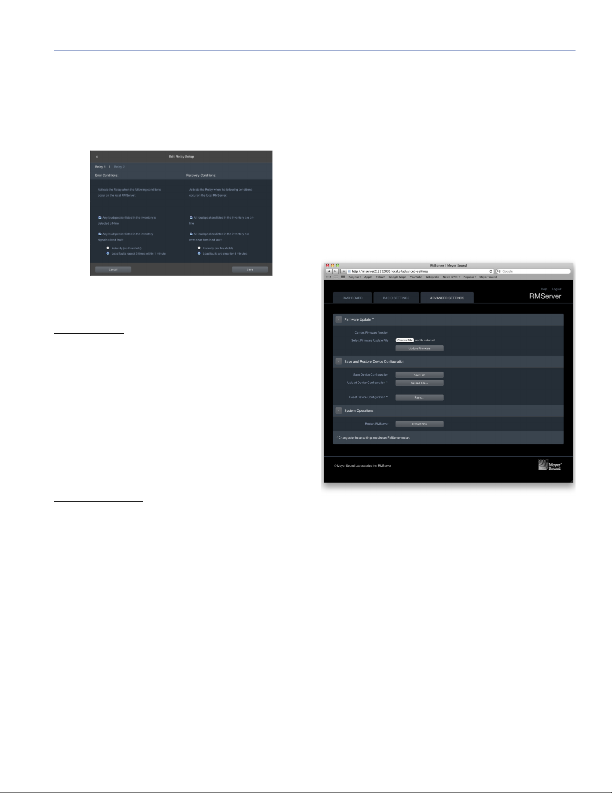
Edit Relay Setup Dialog**
Figure 11: Relay behavior is defined in the Edit Relay Setup dialog.
Relay 1/Relay 2: Click one of these legends at the top of the
dialog to edit settings for the selected relay.
Error Conditions
This section provides check boxes for the error conditions
that will trigger a state change of the relay being edited. The
relay will change state if either of the specified conditions
occurs.
Test Relay Status Dialog
Displays the current status of Relay 1 and Relay 2. The button next to each line changes the state of the indicated relay.
Click the Done button or the close box at the top left to
close the dialog and save the settings.
NOTE: Relays remain in the state indicated in the
Test Relay Setup dialog after it is closed. They are not
reset to the value they were in when the dialog was
opened.
Advanced Settings
Any loudspeaker listed in the inventory is detected off-line.
Any loudspeaker listed in the inventory signals a load fault:
For this condition, one of the associated radio buttons must
be chosen.
Instantly (no threshold)
Load faults repeat 3 times within 1 minute.
Recovery Conditions
This section provides check boxes for the conditions indicating restoration of normal operation that will trigger a state
change of the relay being edited. The relay will change state
if either of the specified conditions occurs.
All loudspeakers listed in the inventory are on-line
All loudspeakers listed in the inventory are now clear from
load fault: For this condition, one of the associated radio
buttons must be chosen.
Instantly (no threshold)
Load faults are clear for 5 minutes.
Click the Save button in the lower right to save the settings.
The Cancel button in the lower left exits the dialog without
saving changes. A close box for the dialog is in the upper
left corner.
Figure 12: The Advanced Settings page of RMServer's web server.
NOTE: Changes to settings in this section that are
marked with a double asterisk ( **) take effect after
RMServer has been restarted.
Firmware Update**
Current Firmware Version: Displays currently installed firmware version.
Select Firmware Update File: The Choose File button opens
a file browser for navigating to and selecting firmware
update files. When a file is selected, its name is displayed
next to the button.
Update Firmware button: Clicking this button begins execution of the firmware update process using the selected file
shown above.
17
Page 18
CHAPTER 2: INSTALLING AND CONFIGURING RMSERVER
For a complete firmware update procedure, see the section
“Updating RMServer's Firmware” on page 18.
Save and Restore Device Configuration
A device configuration file contains all of the settings from
the Basic Settings and Advanced Settings pages of the
RMServer web server page.
Save Device Configuration: Clicking the Save File button
saves the current device configuration to a file in your computer's default user Downloads folder.
Upload Device Configuration**: Clicking the Upload File button opens a file browser. Navigate to and select the Device
Configuration file you wish to upload to RMServer.
Reset Device Configuration**: Clicking the Reset button
restores factory default values for RMServer.
System Operations
Restart RMServer: Clicking the Restart Now restarts
RMServer, which reloads settings. Click this button after
making changes to sections marked with a double asterisk
(**) to make the changes take effect.
2. Click the Restart Now button in the System Operations
section of the Advanced Settings tab of RMServer's web
server to restart RMServer and reload the current settings.
3. Hold the Reset button on the front panel down for five
seconds while RMServer is running to restart RMServer
and restore the factory default settings.
4. Holding the Reset button on the front panel while powering on RMServer will restart the unit in failsafe mode.
Continue holding the Reset button until the Fault LED
remains solid.
When the power LED stays on solid, restart is complete. In
failsafe mode, the power LED flashes slowly.
NOTE: In the initial release of RMServer (with Com-
pass 3.0.0), if you are using Bonjour to communicate
with RMServer, the web server login page will not be
automatically displayed when restarting is complete.
However, the login page is easily accessed using any
of the regular methods.
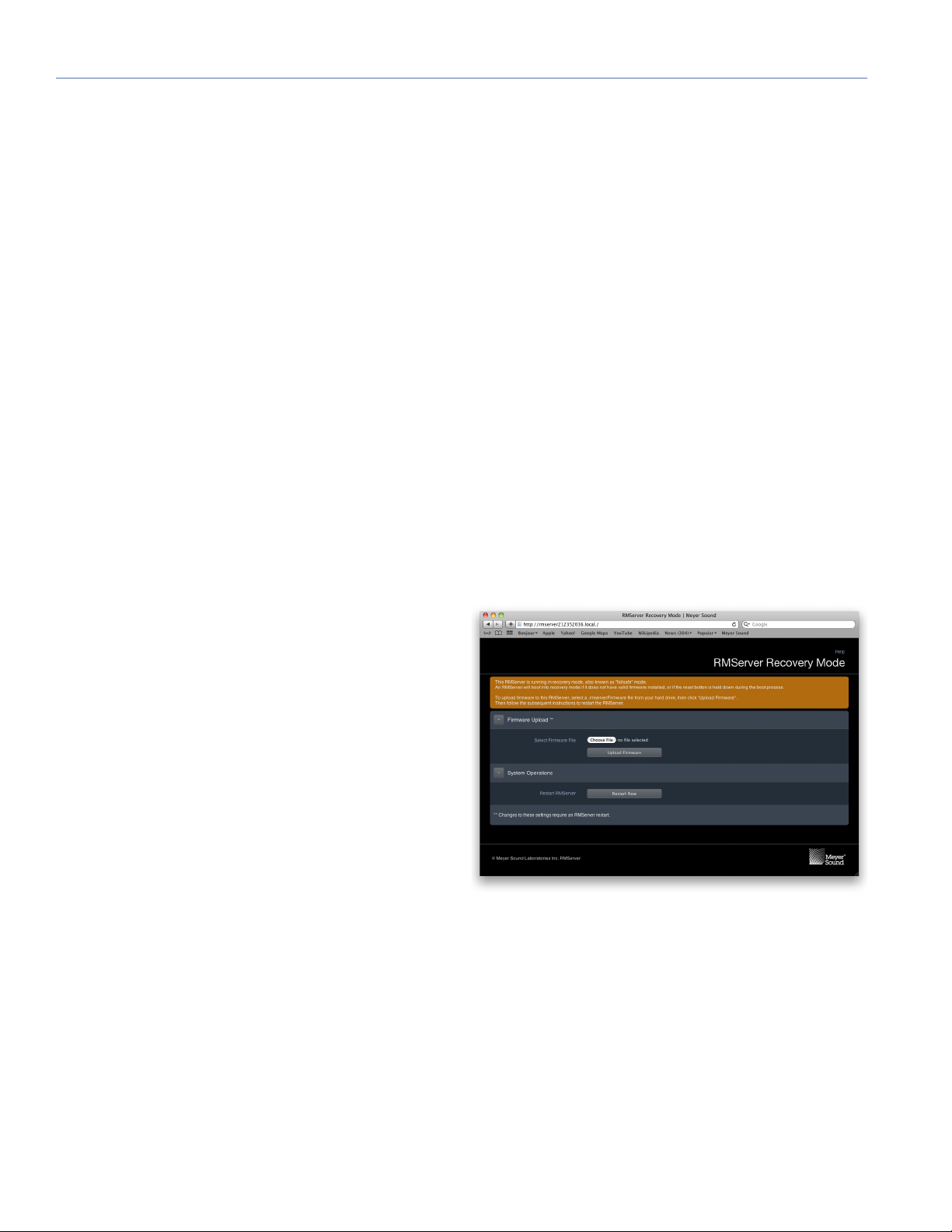
RMServer Failsafe (Recovery) Mode
Updating RMServer's Firmware
1. Login to the RMServer web server.
2. Access the Advanced Settings tab of the RMServer web
server.
3. Click the Choose File button in the Firmware Update
section to open a file browser.
4. Navigate to the firmware update file and click OK to
close the dialog.
5. Click the Update Firmware button to start the firmware
updating process.
6. When the updating process completes, restart RMServer
by clicking the Restart Now button in the dialog that
appears.
Restarting RMServer
There are four ways to restart RMServer. The front panel
Reset button is recessed, so a paper clip or similarly small
implement is required to press it.
1. Press the Reset button on the front panel once to restart
RMServer and reload the current settings.
Figure 13: The failsafe mode web server page is simpler than the normal
RMServer web server page.
Failsafe mode (also called "recovery" mode) should be
invoked only in cases of serious RMServer problems, such
as a failed firmware update or an inability of RMServer to
boot properly.
18
Page 19

If the unit does not boot, enter failsafe mode as described
above and then point your browser to the web server page.
The failsafe web server page is much simpler than the regular web server page, allowing only firmware updates (along
with updating instructions).
If RMServer cannot load the most recent firmware when it
boots up, it will try the previous version that was installed. If
neither one works, it will boot into failsafe mode on its own.
RMS USER GUIDE
19
Page 20

CHAPTER 2: INSTALLING AND CONFIGURING RMSERVER
20
Page 21

CHAPTER 3: CONNECTING RMS NETWORKS
This chapter documents connecting RMS networks and
includes the following topics:
■ “Network Specifications” on page 21
■ “Twisted-Pair Cabling” on page 21
■ “Ethernet Hubs and Switches” on page 22
■ “Design Tips for RMS networks” on page 23
■ “Ethernet Configurations” on page 24
NETWORK SPECIFICATIONS
Maximum Loudspeaker Nodes
■ 50 for each RMServer
NOTE: Each MPS-488HP power supply occu-
pies the bandwidth of four normal loudspeakers (four nodes). Bandwidth restrictions dictate that a
maximum of 12 MPS-488HPs can be connected to a
single network interface or RMServer
NOTE: The SB-3F loudspeaker occupies the
bandwidth of two normal loudspeakers. Therefore, a maximum of 25 SB-3F loudspeakers can be
connected to single network interface or RMServer
Maximum Network Length (without Repeaters)
■ Free topology: 500 m (1,640 ft) with 20 AWG, 18 AWG or
16 AWG cable and one 52.3-ohm type terminator
■ Ethernet: 10BASE-T network limitations plus standard
twisted pair limitations
■ Twisted-pair cabling: Total length per network segment
should not exceed 1640 ft (500 m). For systems with network repeaters, the distance to the first loudspeaker also
should not exceed 1640 ft (500 m).
NOTE: For optimum performance, the twisted-
pair cabling between RMServer and first loud-
speaker should not exceed 1,450 ft (450 m).
Termination
■ Free topology: One 52.3-ohm type terminator at any
point
Network Platform
■ Differential Manchester encoding; polarity insensitive,
free topology
Transceiver
■ EMI, complies with FCC Part 15, Class A; UL recognized;
VDE, EMI compliant
Cable Type
■ Twisted-pair: 20 AWG (Belden 8205 or equivalent)
twisted pair, stranded, unshielded
■ Low-voltage; Multi-conductor multimedia control cable
(Belden 1502R or equivalent)
■ Ethernet: Category 5 (Cat 5) or higher specification
NOTE: The maximum length for Ethernet
cables is 328 ft (100 m). When connecting
RMServer to an Ethernet hub or switch, use a
straight-through (patch) cable. When connecting
directly to a computer Ethernet port, use a crossover
cable.
Connector Type
■ Twisted pair: Weidmuller 2-conductor locking connector
■ Ethernet: 10BASE-T, type RJ-45
■ Portable: XLR and EN3
Data Rate
■ 200 ms transfer rate with 20 loudspeakers
CAUTION: Compass RMS software and hard-
ware components interact continuously, communicating information about the connected
loudspeakers to the host computer. If the network is
overloaded, critical data may reach the host computer very slowly, or not at all. Meyer Sound recommends that Ethernet-based RMS configurations be
deployed as a closed network, to reduce congestion
from outside network activity. All Galileo units in the
system should be on this network.
TWISTED-PAIR CABLING
The Weidmuller Network connectors on RMS modules are
connected via twisted-pair cables. The twisted-pair cabling
is connected directly to RMServer .
21
Page 22
CHAPTER 3: CONNECTING RMS NETWORKS
,OOP
)NPUT
#
#
.ET WOR K
3ER
VICE
7
I
NK
2ES
E
T
!CT I
VI
T
Y
2EM OT E -O NI TOR
4O,OUDSPEAKER
3ERVER#05(OST
4O#05
Y
Free Topology twisted-pair technology allows a nearly
infinite number of ways to wire RMS-equipped loudspeakers. However, an individual Free Topology network can
address a maximum of 50 loudspeaker nodes over a maximum length of 500 meters (1640 feet) using 20 AWG cable
(Belden 8205 or equivalent) and a single bus terminator. A
double-terminator topology allows a maximum cable length
of 1400 meters (4593 feet) when using 22 AWG cable, and
2700 meters (8858 feet) using 16 AWG cable.
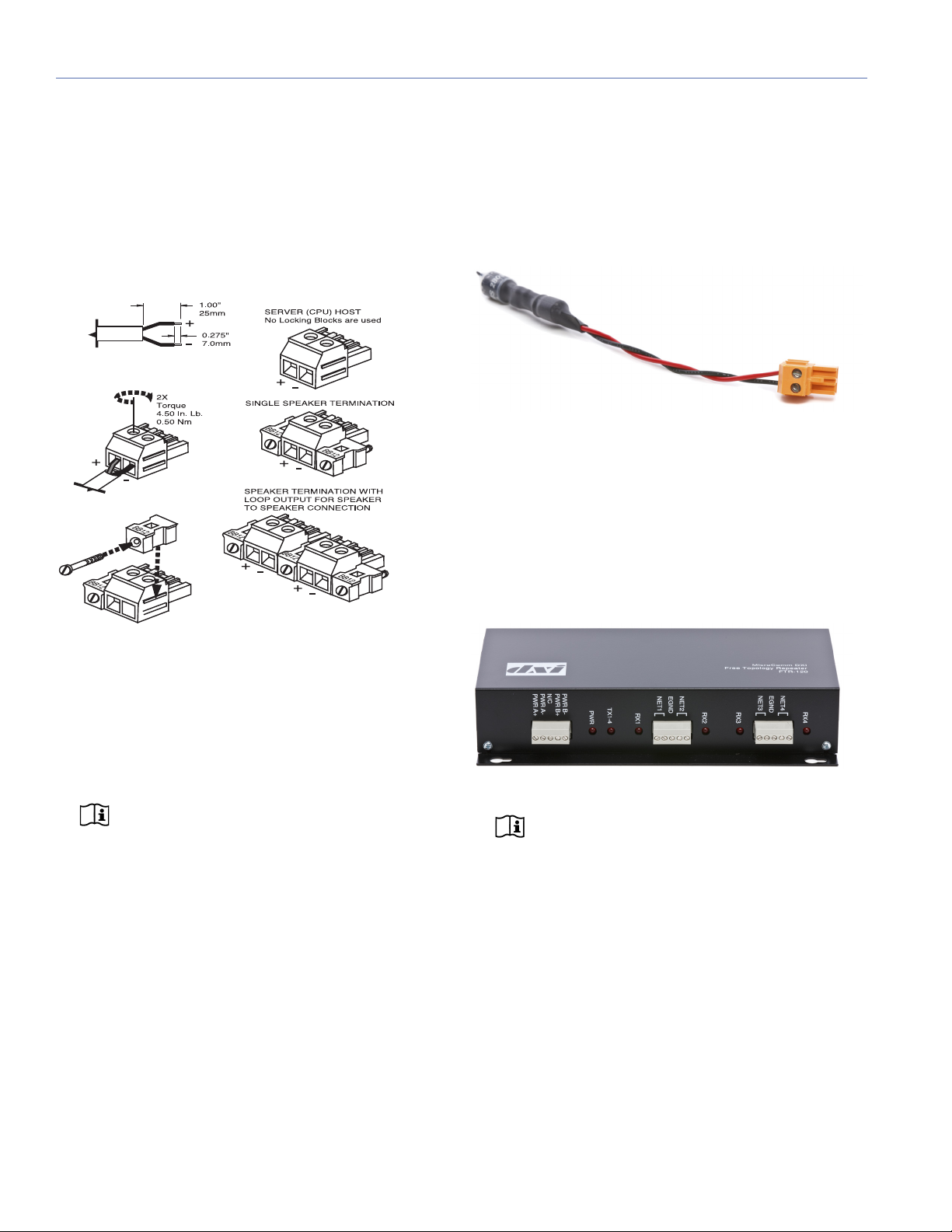
Network Terminators
An RMS network terminator is a simple resistive, capacitive
device designed to prevent electrical reflections on the network. Each RMServer contains switchable onboard termination. If needed, additional terminators can be installed at
almost any location in the network depending on the topology used.
Figure 2: An RMS network terminator
Network Repeaters
A network repeater (such as the FTR-120 Free Topology
Repeater from MicroComm DXI) connects multiple segments of network cabling. It re-times, strengthens, and
regenerates the signal and sends it back to the network. A
network repeater allows you to increase the geographical
coverage of an RMS network.
Figure 1: Twisted-pair connectors for RMS-equipped devices
To reduce the amount of twisted-pair cabling in an RMS network, groups of neighboring loudspeakers can be daisy
chained.
to RMServer can be spliced at a junction box or breakout
panel with multiple outputs that can be patched to multiple
In addition, a twisted-pair cable connected directly
loudspeaker destinations.
NOTE: Multiple RMServers are required if you
want to connect more than 50 device nodes
(loudspeakers, etc.) to a host computer running the
Compass RMS system.
traffic capacity of the network as well as the signal
strength over longer cable runs.
This will increase the data
Custom Twisted-Pair Connectors
When designing twisted-pair cable runs, you can use custom connectors (such as 5-pin XLR connectors) or terminal
blocks to make the installations more user-friendly. This is
common for theater and touring applications.
Figure 3: FTR-120 Network Repeater
NOTE: For information on using the FTR-120
Free Topology Repeater, see Appendix D,
“FTR-120 Free Topology Repeater.”
ETHERNET HUBS AND SWITCHES
A hub is a device that joins multiple computers or other network devices to form a single network. Switches are similar
to hubs but are more intelligent; they can inspect data as it
is received, determine the source and destination of the
data, and forward it appropriately. Switches conserve network bandwidth and offer better performance than hubs.
A hub or a switch is needed for RMS networks containing
multiple RMServers, or if you are sharing an existing Ethernet network connection.
22
Page 23

DESIGN TIPS FOR RMS NETWORKS
Different designs have their own strengths and weaknesses.
The following tips will help you make the most of your RMS
network design:
■ Avoid making “dedicated single runs” for each loud-
speaker when designing a system. Make only a single
twisted-pair run to loudspeaker locations or arrays when
possible. Once you have reached the loudspeaker array
location, daisy chain or loop through all the loudspeakers
in the array. This will help reduce cable load on the network.
CAUTION: If you must make dedicated
twisted-pair runs to each loudspeaker (for
example, when using VEAM connectors) do not
exceed the total recommended cable length
(1,640 ft), or plan on using a repeater to minimize
data loss.
■ Use a single twisted-pair run from the RMServer location
to a breakout panel. Locate RMServer as close as possible to the breakout panel, which should itself be located
as close as possible to the loudspeakers.
RMS USER GUIDE
■ If you are receiving poor data or experiencing other com-
munications problems, use a terminator in the network to
help increase network stability.
■ When using a venue’s existing Ethernet-based network,
work with the venue’s IT department to reserve static IP
addresses for the RMS network.
■ When possible, use a closed Ethernet-based network to
reduce congestion from outside network activity.
23
Page 24

CHAPTER 3: CONNECTING RMS NETWORKS
Compass Control
Software
Mac or Windows
Compass Control
Software
Mac or Windows
Network Switch
BDF
ANALOG
(DISABLED FOR
AES/EBU)
A
12345678
9101112
OUTPUT
INPUT
13 14 15 16
CE
ANALOG OR
AES/EBU STEREO
Connect to SIM
3022 or 3088 only
C
E
INP
UT
CAT 5E or Better Network Cable
RMS FT-10 Twisted Pair Network Cable
Belden® 8205
ETHERNET CONFIGURATIONS
Figure 4, Figure 5, and Figure 6 illustrate some basic Ethernet configurations.
NOTE: The maximum length for Ethernet
cables is 328 ft (100 m). Do not exceed this
length when connecting RMServer s to your computer, as well as to Ethernet switches and hubs.
NOTE: Ethernet-based RMS systems must
conform to Ethernet network design specifications, which are beyond the scope of this manual. A
general knowledge of Ethernet networks is very helpful in planning Compass RMS systems.
NOTE: A closed, separate Ethernet network is
recommended for Compass RMS systems to
reduce congestion from outside network traffic. All
Galileo units in the system should be on this network.
Figure 4: Basic RMS network with a single RMServer (top) and with multiple RMServers, Callisto, and a router (bottom).
24
Page 25

RMS USER GUIDE
Intranet
Compass Control
Software
Mac or Windows
CAT 5E or Better Network Cable
RMS FT-10 Twisted Pair Network Cable
Belden® 8205
Figure 5: Basic Ethernet Configuration Using Existing Intranet Infrastructure
25
Page 26

CHAPTER 3: CONNECTING RMS NETWORKS
FTR-120
NETWORK REPEATER
12V D/C
Power Supply
RMS looped to loudspeakers
Compass Control
Software
Mac or Windows
Repeater is required when
cable length exceeds 1640 feet
CAT 5E or Better Network Cable
RMS FT-10 Twisted Pair Network Cable
Belden® 8205
Ethernet and Twisted-Pair Hybrid System (Large Venue Applications)
For larger venues such as theatres, stadiums, arenas,
hotels, and theme parks, systems using multiple RMServers
are preferred for increased network speed.
In large systems, long cable runs can be required from an
RMServer to the loudspeaker locations. One or more FTR120 repeaters can be incorporated to extend the maximum
cable run length. This forms a hybrid network of twisted-pair
and Ethernet cabling.
Figure 6: A large system using an FTR-120 repeater.
26
Page 27

Star Topology with Low Voltage Systems and Junction Point
Compass Control
Software
Mac or Windows
Custom RMS Hub or
Junction Point
MPS-488HP = 4 RMS network nodes
MPS-488HP = 4 RMS network nodes
Network Switch
AC INPUT
100--240V
~
60 Hz 830W MAX
EACH OUTPUT: 48VDC 96VA MAX. WARNING: Risk of Fire or Electric Shock. Do not interconnect output terminations.
LINK
IN 8IN 7IN 6IN 5IN 4IN 3IN 2IN 1
1 GND
2 +
3 --
AUDIO
PUSH
PUSHPUSHPUSHPUSHPUSHPUSHPUSH
OUT 8OUT 7OUT 6OUT 5OUT 4OUT 3OUT 2OUT 1
NOTE: NEC ANSI/NFPA 70 Class 2 Wiring may be used
48 VDC
+
--
S
+
--
AUDIO
RMS Network
Identity
Wink
Activity
CAT 5E or Better Network Cable
RMS FT-10 Twisted Pair Network Cable
Belden® 8205
Composite Multiconductor Cable
Belden® 1502
The MPS-488HP power supply is used in low-voltage systems. It is important to note that each MPS-488HP consumes four RMS nodes, regardless of how many
loudspeakers are actually connected to it. The junction point
illustrates the flexibility of a free topology network.
RMS USER GUIDE
Figure 7: A large system using a junction box and multiple MPS-488HPs. All junction point output ports are in parallel.
27
Page 28

CHAPTER 3: CONNECTING RMS NETWORKS
28
Page 29

CHAPTER 4: HP/MP RMS MODULE
The HP/MP RMS module is used in the following loudspeakers with HP-2, HP-4, MP-2, and MP-4 amplifiers.
Table 1: MP/HP Amplifier RMS Module
Part Number Series Loudspeakers
40.033.071.01 M-Series M2D-Sub, M3D, M3D-Sub, MICA,
MILO 60, MILO 120
Concert
Series
Industrial
Series
EXP
Series
600-HP, 700-HP, 650-P, DF-4, DS-2P,
DS-4P, MSL-4, MSL-6, MTS-4,
PSM-2, PSW-2, PSW-4, PSW-6,
SB-1, SB-2, SB-3F
Acheron 100, Acheron 80, Acheron LF
When equipped with an RMS module, Meyer Sound loudspeakers can be connected to an RMS network and monitored with Compass control software. Some Meyer Sound
loudspeakers, such as the M-Series loudspeakers, come
standard with an RMS module already installed. For other
Meyer Sound loudspeakers, an RMS module is available as
an option that can either be factory installed or installed at a
later date by a qualified service technician.
The following sections document how to install and use the
HP/MP RMS module:
■ “Installing the HP/MP RMS Module” on page 29
■ “Installing the Mute Jumper on the HP/MP RMS Module”
on page 33
INSTALLING THE HP/MP RMS MODULE
This section documents installing the HP/MP RMS module.
The installation procedure requires the following:
■ Standard #2 Phillips screwdriver
■ 3/8-inch nut driver
■ Fluke 87 multimeter or equivalent ohmmeter
NOTE: Before adding an RMS module to loud-
speakers with amplifiers manufactured before
1997, the loudspeakers must be retrofitted with TPL
control boards and RMS-ready user panels. The first
two digits of the loudspeaker’s serial number indicate
its year of manufacture; serial numbers starting with
96 or a lower number require retrofitting. For information, contact Meyer Sound Technical Services.
NOTE: Make sure to hold the HP/MP RMS
module by its edges. Avoid touching any of the
components on the module.
To install the HP/MP RMS module:
1. Remove the loudspeaker’s AC power cable and audio
cable and place the loudspeaker on a clean, low-static
firm surface. Orient the loudspeaker with the top facing
up. Wait at least five minutes before removing the HP/MP
RMS module.
■ “HP/MP RMS User Panel” on page 34
■ “Neuron ID for HP/MP RMS Modules” on page 34
■ “Resetting the HP/MP RMS Module” on page 35
NOTE: The HP/MP RMS module includes a
Mute Jumper that enables the loudspeaker’s
mute and solo capability when installed. Meyer
Sound currently ships RMS-equipped loudspeakers
with the Mute Jumper installed. These mute-enabled
loudspeakers can be identified by the blue “ME”
sticker on the HP/MP RMS user panel. Older RMSequipped loudspeakers can be easily mute-enabled
by installing the Mute Jumper. For more information,
see “Installing the Mute Jumper on the HP/MP RMS
Module” on page 33.
29
Page 30

CHAPTER 4: HP/MP RMS MODULE
2. To remove the amplifier from the loudspeaker cabinet:
■ Remove the eight large screws that secure the amplifier
to the cabinet.
■ Remove the amplifier from the cabinet slowly, taking care
to unplug the green loudspeaker connector on the top
side of the amplifier (there are two connectors for the
four-channel amplifiers).
■ While carefully removing the user panel, disconnect from
the user panel the signal cable from the input board (with
the gray connector), and disconnect from the AC mains
board the AC input cable (4-wire, green connector) from
the user panel.
■ Place the amplifier on a flat surface that is stable, clean,
and low-static.
3. To remove the user panel from the amplifier:
■ Remove the eight small screws from the user panel.
4. Remove the blank cover plate from the user panel by
removing the two nuts on the back of the user panel.
5. In the power supply chassis, locate the back right screw
hole (next to the transformer) on the floor of the chassis.
If the paint around the hole has not been sufficiently
removed (to allow for metal-to-metal contact with the
30
Page 31

RMS USER GUIDE
Rear right
screw hole
Plastic
connector
module standoff), remove the paint with a Dremel® tool
or sandpaper. Make sure to remove all debris from the
chassis before proceeding.
CAUTION: Do not grind down the metal
around the screw hole too much. If the metal is
too thin it will reduce the metal-to-metal contact (and
grounding) with the HP/MP RMS module.
7. Apply one drop of Loctite
®
to each of the four standoffs
on the HP/MP RMS module and then place the module
in the bottom of the power supply chassis with the LEDs
facing out and the standoffs aligned with the four screw
holes in the bottom of the chassis.
6. Remove the plastic connector on the power supply
board (next to the fan power connector).
31
Page 32

CHAPTER 4: HP/MP RMS MODULE
R13
8. Attach the short 9-wire gray ribbon cable from the
HP/MP RMS module to the connector on the power supply board. Make sure all pins are engaged and that the
connector is firmly seated.
9. While holding the HP/MP RMS module in place, place
the loudspeaker on its side and secure the module using
the four screws included with the kit.
10. Attach the 26-pin connector from the long ribbon cable
to the HP/MP RMS module connector. Make sure to fully
lock the connector.
11. Using an ohmmeter, measure the resistance for R13 on
the HP/MP RMS module. R13 is located about an inch to
the right of the center of the module. The resistance
should measure 10 ohms. If the resistance measures
47 ohms, the module is insufficiently grounded.
32
NOTE: Insufficient grounding may be caused
by too much paint surrounding the back right
screw hole (see Step 5), or it may be caused by overthinning the screw hole (if this is the case, a shorter
screw may fix the problem).
NOTE: The resistance for R13 will not read
10 ohms if the ribbon cable from the HP/MP
RMS module was not connected to the power supply
board (see Step 8).
Page 33

RMS USER GUIDE
Neuron ID label
Install here
12. Reconnect the AC input cable (4-wire, green connector)
from the user panel to the AC mains board. Reconnect
the signal cable from the input board (gray multipin connector) to the user panel. Make sure to fully lock the gray
multipin connector.
13. While carefully aligning the HP/MP RMS module’s network connectors and LEDs with the user panel, secure
the user panel to the amplifier with the eight small
screws.
14. Reconnect the green connector from the loudspeaker
cabinet to the top of the amplifier (there are two connectors for the four-channel amplifiers), then carefully slide
the amplifier back in the cabinet and secure it with the
eight large screws.
INSTALLING THE MUTE JUMPER ON THE HP/MP RMS MODULE
To use the mute and solo functions of the HP/MP RMS module, the Mute Jumper must be installed on the module.
Meyer Sound currently ships RMS-equipped loudspeakers
with the Mute Jumper installed. These mute-enabled loudspeakers can be identified by the blue “ME” sticker on the
HP/MP RMS user panel. Older RMS-equipped loudspeakers can be easily mute-enabled by installing the Mute
Jumper, available from Meyer Sound in a mute jumper kit,
P/N 476.005 RMS Mute Enable Replacement Upgrade
Jumper.
ME Sticker
To install the Mute Jumper on the HP/MP RMS module:
1. Remove the loudspeaker’s AC power cable and then
wait at least five minutes before removing the HP/MP
RMS module.
2. On the HP/MP RMS module, locate the two (J3) jumper
pins labeled SHORT TO ENABLE MUTE and install the
blue Mute Jumper on these two pins.
15. Affix the Neuron ID label to the bottom center of the user
panel, directly below the HP/MP RMS module’s LEDs
and network connectors.
16. Reconnect the loudspeaker’s AC power cable and audio
cable and apply power to the loudspeaker. The Activity
LED blinks to indicate the HP/MP RMS module is operational and ready to be discovered on the network.
RMS Mute Jumper
HP/MP RMS Module Jumper Pins
33
Page 34

CHAPTER 4: HP/MP RMS MODULE
CAUTION: Do not mistakenly install the Mute
Jumper on the white, unlabeled two-pin connector on the HP/MP RMS module. This connector is
for the VEAM connector option; using it for any other
purpose will damage the module.
3. Reinstall the HP/MP RMS module in the loudspeaker.
HP/MP RMS USER PANEL
The HP/MP RMS user panel has three LEDs, two buttons,
and two Network connectors.
Figure 8: HP/MP RMS Module
NOTE: The buttons and LED on the HP/MP
RMS user panel are used exclusively by Compass RMS and have no effect on the acoustical or
electrical activity of the loudspeaker.
Service LED (Red)
The red Service LED provides the following feedback:
■ When unlit, the loudspeaker is successfully connected to
the network and discovered.
Wink LED (Green)
The green Wink LED lights when a signal is sent from Compass by clicking the Wink button on a loudspeaker object in
meter view on a user page. This is useful for identifying the
physical loudspeaker corresponding to a loudspeaker icon
in Compass.
Reset Button
Pressing the Reset button causes the HP/MP RMS module’s
firmware to reboot; this will not affect whether the loudspeaker is discovered (which is stored in flash memory). You
can simultaneously press the Reset and Service buttons to
reset the HP/MP RMS module, undiscover the loudspeaker,
and remove it from the RMServer inventory (see “Resetting
the HP/MP RMS Module” on page 35).
Activity LED (Green)
The green Activity LED flashes continuously when the loudspeaker has been successfully discovered.
RMS Network Connectors
The two Weidmuller connectors transfer data to and from
the RMS network. Two connectors are provided to allow for
easy connection of multiple (daisy-chained) loudspeakers
on the network. Included with each RMS-equipped loudspeaker are RMS cable connectors and mounting blocks for
constructing RMS cables. The RMS blocks allow the cables
to be securely attached to the RMS module with screws.
■ When blinking once every two seconds, the loudspeaker
is connected to the network but not yet discovered in
Compass.
■ When lit continuously, the loudspeaker’s RMS hardware
has failed and may indicate that the module has been
damaged (contact Meyer Sound Technical Support).
Service Button
Pressing the Service button identifies the loudspeaker in the
Compass RMS system and notifies Compass that the loudspeaker is connected. You can simultaneously press the
Reset and Service buttons to reset the HP/MP RMS module,
undiscover the loudspeaker, and remove it from the
RMServer inventory (see “Resetting the HP/MP RMS Module” on page 35).
34
NEURON ID FOR HP/MP RMS MODULES
Each HP/MP RMS module has a unique 12-character Neuron ID (NID) that identifies the loudspeaker on the network.
The NID should be discovered automatically by the
RMServer to which it is connected, but can be entered manually, if necessary. The NID for the HP/MP RMS module is
located on the user panel below the orange RMS Network
connectors (see Figure 8 on page 34).
Page 35

RESETTING THE HP/MP RMS MODULE
You can use the Reset and Service buttons to reset the
HP/MP RMS module, which will cause the module to be
undiscovered and removed from the RMServer inventory.
To reset the HP/MP RMS module:
1. Press and hold the Service button for 10 seconds.
2. While continuing to hold down the Service button, press
and hold the Reset button for 5 seconds.
3. After releasing the Reset button, continue holding down
the Service button for 5 seconds. The HP/MP RMS module is reset and the loudspeaker is undiscovered and
removed from the RMServer inventory. The HP/MP RMS
module’s red Service LED blinks.
RMS USER GUIDE
35
Page 36

CHAPTER 4: HP/MP RMS MODULE
36
Page 37

CHAPTER 5: ULTRASERIES RMS MODULE
There are two UltraSeries RMS modules, which are used in
the following loudspeakers.
Table 2: UltraSeries RMS Modules
Part Number Series Loudspeakers
40.084.008.01
(UX)
40.076.028.01
(UPM)
M-Series M1D, MD1-Sub, M’elodie
UltraSeries 500-HP, JM-1P, MJF-212,
MJF-212A, UMS-1P, UPJ-1P,
UPJunior, UPM-1P, UPM-2P,
UPQ-1P, UPQ-2P
JM Series JM-1P
M-Series M2D
UltraSeries UPA-1P, UPA-2P, UM-1P,
UM-100P, USM-1P, USM-100,
USW-1P
EXP Series Acheron Studio
When equipped with an RMS module, Meyer Sound loudspeakers can be connected to an RMS network and monitored with Compass. Some Meyer Sound loudspeakers,
such as the M-Series loudspeakers, come standard with the
RMS module already installed. For other Meyer Sound loudspeakers, the RMS module is available as an option that can
either be factory installed or installed at a later date by a
qualified service technician.
The following sections document how to install and use the
UltraSeries RMS module:
by installing the Mute Jumper. For more information,
see “Installing the Mute Jumper on the UltraSeries
RMS Module” on page 38.
ME Sticker
INSTALLING THE ULTRASERIES RMS MODULE
This section documents installing the RMS module in UltraSeries loudspeakers. The same procedure can also be used
to install or replace an RMS module in several of the
M-Series loudspeakers (see Table 2). This installation procedure requires a standard #2 Phillips screwdriver.
NOTE: If you want to enable muting capability
for the loudspeaker, make sure to install the
Mute Jumper on the RMS module before installing it.
For more information, see “Installing the Mute
Jumper on the UltraSeries RMS Module” on page 38.
NOTE: The illustrations in the following proce-
dure show the UltraSeries UX RMS module.
However, this procedure is the same for UltraSeries
UPM RMS modules.
■ “Installing the UltraSeries RMS Module” on page 37
■ “Installing the Mute Jumper on the UltraSeries RMS
Module” on page 38
■ “UltraSeries RMS User Panel” on page 39
■ “Neuron ID for UltraSeries RMS Modules” on page 40
■ “Resetting the UltraSeries RMS Module” on page 40
NOTE: The UltraSeries RMS module includes a
Mute Jumper that when installed enables the
loudspeaker’s mute and solo capability. Meyer Sound
currently ships RMS-equipped loudspeakers with the
Mute Jumper installed. These mute-enabled loudspeakers can be identified by the blue “ME” sticker
on the UltraSeries RMS user panel. Older RMSequipped loudspeakers can be easily mute-enabled
NOTE: Make sure to hold the UltraSeries RMS
module by its edges. Avoid touching any of the
components on the module.
37
Page 38

CHAPTER 5: ULTRASERIES RMS MODULE
Copper strip
Locking
connector
To install the UltraSeries RMS module:
1. Remove the loudspeaker’s AC power cable and audio
cable and place the loudspeaker on a clean, low-static
flat surface. Orient the loudspeaker with the top facing
up. Wait at least five minutes before removing the UltraSeries RMS module.
2. Remove the four screws securing the cover plate for the
slot below the audio input module. Save the cover plate
in case you need it in the future.
4. Locate the ribbon cable beneath the audio input module
and attach this cable to the rear connector on the UltraSeries RMS module. Make sure to fully lock the connector.
5. Slide the UltraSeries RMS module into the open slot
(below the audio input module) and secure it with the
four screws.
6. Reconnect the loudspeaker’s AC power cable and audio
cable and apply power to the loudspeaker. The Activity
LED blinks to indicate the UltraSeries RMS module is
operational and ready to be discovered on the network.
3. Verify that the copper strip on the left side of the open
slot is not damaged and properly positioned. The copper
strip helps ground the UltraSeries RMS module to the
chassis. If you need to replace the copper strip, contact
Meyer Sound.
INSTALLING THE MUTE JUMPER ON THE ULTRASERIES RMS MODULE
To use the mute and solo functions of the UltraSeries RMS
module, the Mute Jumper must be installed on the module.
Meyer Sound currently ships RMS-equipped loudspeakers
with the Mute Jumper installed. These mute-enabled loudspeakers can be identified by the blue “ME” sticker on the
UltraSeries RMS user panel. Older RMS-equipped loudspeakers can be easily mute-enabled by installing the Mute
Jumper, available from Meyer Sound in a mute jumper kit, P/
N 476.005 RMS Mute Enable Replacement Upgrade
Jumper.
CAUTION: Do not mistakenly install the Mute
Jumper on the white, unlabeled two-pin connector on the UltraSeries RMS module. This connector is for the VEAM connector option; using it for any
other purpose will damage the module.
38
Page 39

RMS USER GUIDE
Install here
Install here
To install the Mute Jumper on the UltraSeries RMS module:
1. Remove the loudspeaker’s AC power cable and then
wait at least five minutes before removing the UltraSeries
RMS module.
2. On the UltraSeries RMS module, locate the two (J3)
jumper pins labeled SHORT TO ENABLE MUTE and
install the blue Mute Jumper on these two pins.
RMS Mute Jumper
ULTRASERIES RMS USER PANEL
The UltraSeries RMS user panel has three LEDs, two buttons, and two Network connectors.
Figure 9: UltraSeries RMS Module (UX, PN 40.084.008.01)
Figure 10: UltraSeries RMS Module (UPM, PN 40.076.028.01)
NOTE: The buttons and LEDs on the
UltraSeries RMS user panel are used exclusively by Compass RMS and have no effect on the
acoustical or electrical activity of the loudspeaker.
UltraSeries (UPM) RMS Module Mute Jumper Pins
Service LED (Red)
The red Service LED provides the following feedback:
■ When unlit, the loudspeaker is successfully connected to
the network and discovered.
■ When blinking once every two seconds, the loudspeaker
is connected to the network but not yet discovered in
Compass.
■ When lit continuously, the loudspeaker’s RMS hardware
has failed and may indicate that the module has been
damaged (contact Meyer Sound Technical Support).
Service Button
Pressing the Service button identifies the loudspeaker in the
Compass RMS system and notifies Compass that the loudspeaker is connected. You can simultaneously press the
Reset and Service buttons to reset the UltraSeries RMS
module, undiscover the loudspeaker, and remove it from the
RMServer inventory (see “Resetting the UltraSeries RMS
Module” on page 40).
UltraSeries (UX) RMS Module Mute Jumper Pins
3. Reinstall the UltraSeries RMS module in the loudspeaker.
39
Page 40

CHAPTER 5: ULTRASERIES RMS MODULE
Wink LED (Green)
The green Wink LED lights when a signal is sent from Compass by clicking the Wink button on a loudspeaker object in
meter view on a user page. This is useful for identifying the
physical loudspeaker corresponding to a loudspeaker icon
in Compass.
Reset Button
Pressing the Reset button causes the UltraSeries RMS
module’s firmware to reboot; this will not affect whether the
loudspeaker is discovered (which is stored in flash memory).
You can simultaneously press the Reset and Service buttons
to reset the UltraSeries RMS module, undiscover the loudspeaker, and remove it from the RMServer inventory (see
“Resetting the UltraSeries RMS Module” on page 40).
Activity LED (Green)
The green Activity LED flashes continuously when the loudspeaker has been successfully discovered
RESETTING THE ULTRASERIES RMS MODULE
You can use the Reset and Service buttons to reset the
UltraSeries RMS module, which will cause the module to be
reset, and loudspeaker to be undiscovered and removed
from the RMServer inventory.
To reset the UltraSeries RMS module:
1. Press and hold the Service button for 10 seconds.
2. While continuing to hold down the Service button, press
and hold the Reset button for 5 seconds.
3. After releasing the Reset button, continue holding down
the Service button for 5 seconds. The UltraSeries RMS
module is reset and the loudspeaker is undiscovered and
removed from the RMServer inventory. The UltraSeries
RMS module’s red Service LED blinks.
RMS Network Connectors
The two Weidmuller connectors transfer data to and from
the RMS network. Two connectors are provided to allow for
easy connection of multiple (daisy-chained) loudspeakers
on the network. Included with each RMS-equipped loudspeaker are RMS cable connectors and mounting blocks for
constructing RMS cables. The RMS blocks allow the cables
to be securely attached to the RMS module with screws.
NEURON ID FOR ULTRASERIES RMS MODULES
Each UltraSeries RMS module has a unique 12-character
Neuron ID (NID) that identifies the loudspeaker on the network. The NID should be discovered automatically by the
RMServer to which it is connected, but can be entered manually, if necessary. The NID for the UltraSeries RMS module
is located on the user panel below the orange RMS Network
connectors (see Figure 9 on page 39 and Figure 10 on
page 39).
40
Page 41

CHAPTER 6: DX RMS MODULE
The DX RMS module is used in the following loudspeakers:
■ M-Series MINA loudspeaker (comes standard)
■ EXP Acheron Designer loudspeaker (optional)
■ X-400C subwoofer (optional)
■ MJF-210 stage monitor (optional)
When equipped with an RMS module, Meyer Sound loudspeakers can be connected to an RMS network and monitored with Compass control software. Some Meyer Sound
loudspeakers, such as MINA, come standard with the RMS
module already installed. For other Meyer Sound loudspeakers, the RMS module is available as an option that can either
be factory installed or installed at a later date by a qualified
service technician.
The following sections document how to install and use the
DX RMS module:
■ “Installing the DX RMS Module” on page 41
■ “DX RMS User Panel” on page 41
■ “Neuron ID for DX RMS Modules” on page 42
■ “Resetting the DX RMS Module” on page 42
4. Slide the DX RMS module into the open slot (below the
audio input module) and secure it with the two screws.
5. Reconnect the loudspeaker’s AC power cable and audio
cable and apply power to the loudspeaker.
NOTE: The RMS modules in Acheron Designer,
MINA, and X-400C cannot be interchanged
with modules for other loudspeaker models.
DX RMS USER PANEL
The DX RMS user panel includes an Identify button, Wink/
Activity LED, Remote Mute switch, and two Network connectors.
INSTALLING THE DX RMS MODULE
This section documents installing the DX RMS module.This
installation procedure requires a standard #2 Phillips screwdriver
NOTE: Make sure to hold the DX RMS module
by its edges. Avoid touching any of the compo-
nents on the module.
To install the DX RMS module:
1. Remove the loudspeaker’s AC power cable and audio
cable and place the loudspeaker on a clean, low-static
flat surface. Orient the loudspeaker with the top facing
up. Wait at least five minutes before removing the DX
RMS module.
2. Remove the two screws securing the cover plate for the
slot below the audio input module. Save the cover plate
in case you need it in the future.
3. Locate the ribbon cable beneath the audio input module
and attach this cable to the rear connector on the DX
RMS module. Make sure to fully lock the connector.
Figure 11: DX RMS Module
NOTE: The button and LEDs on the DX RMS
user panel are used exclusively by Compass
RMS and have no effect on the acoustical or electrical activity of the loudspeaker.
Identify Button
The Identify button serves the following functions:
■ If the loudspeaker has not yet been discovered (Wink/
Activity LED not lit), press the Identify button to identify
the loudspeaker in the Compass RMS system and discover it.
■ To undiscover the loudspeaker and remove it from the
RMServer inventory, press and hold the Identify button
during startup (see “Resetting the DX RMS Module” on
page 42).
■ To wink a discovered loudspeaker, press the Identify but-
ton. The Wink LED on the loudspeaker icon in Compass
lights up and the Wink/Activity LED on the loudspeaker’s
RMS user panel turns solid green. Press the Identify button again to unwink the loudspeaker
41
Page 42

CHAPTER 6: DX RMS MODULE
Wink/Activity LED (Green)
The green Wink/Activity LED indicates the status of the
loudspeaker:
■ During startup, the LED blinks 10 times.
■ If the loudspeaker has not yet been discovered, the LED
is not lit after startup.
■ If the loudspeaker has been successfully discovered, the
LED flashes continuously and flashes more rapidly with
increased data activity.
■ When the loudspeaker is winked, either by clicking the
Wink button in Compass or by pressing the Identify button on the RMS user panel, the LED is solid green.
TIP: The Wink function is useful for identifying
the physical loudspeaker corresponding to a
loudspeaker object in Compass.
Remote Mute Switch
The recessed Remote Mute switch on the DX RMS user
panel determines whether Compass can control muting and
soloing of the loudspeaker. The DX RMS module ships from
the factory with the switch enabled.
NEURON ID FOR DX RMS MODULES
Each DX RMS module has a unique 12-character Neuron ID
(NID) that identifies the loudspeaker on the network. The
NID should be discovered automatically by the RMServer to
which it is connected, but can be entered manually, if necessary. The NID for the DX RMS module is located on the user
panel above the orange RMS Network connectors (see
Figure 11 on page 41).
RESETTING THE DX RMS MODULE
You can use the Identify button to reset the DX RMS module
when powering up the loudspeaker. This will cause the module to be reset, and the loudspeaker to be undiscovered and
removed from the RMServer inventory.
To reset the DX RMS module:
1. Disconnect the loudspeaker’s power cord.
2. Press and hold the Identify button.
3. While continuing to hold down the Identify button, reconnect the power cord.
4. After the Wink/Status LED blinks on and off, release the
Identify button. The DX RMS module is reset and the
loudspeaker is undiscovered and removed from the
RMServer inventory.
RMS Module
■ Disable: When the Remote Mute switch is set to Disable
(to the left), the loudspeaker cannot be muted and
soloed from Compass.
■ Enable: When the Remote Mute switch is set to Enable
(to the right), the loudspeaker can be muted and soloed
from Compass.
RMS Network Connectors
The two Weidmuller connectors transfer data to and from
the RMS network. Two connectors are provided to allow for
easy connection of multiple (daisy-chained) loudspeakers
on the network. Included with each RMS-equipped loudspeaker are RMS cable connectors and mounting blocks for
constructing RMS cables. The RMS blocks allow the cables
to be securely attached to the RMS module with screws.
42
Page 43

CHAPTER 7: MX RMS MODULE
pn 101.567
The MX RMS module is used in the following loudspeakers:
■ LEO-M loudspeaker (comes standard)
■ 1100-LFC loudspeaker (comes standard)
When equipped with an RMS module, Meyer Sound loudspeakers can be connected to an RMS network and monitored with Compass control software. Some Meyer Sound
loudspeakers, including LEO-M and 1100-LFC, come standard with the RMS module already installed. For other
Meyer Sound loudspeakers, the RMS module is available as
an option that can either be factory installed or installed at a
later date by a qualified service technician.
The following sections document how to install and use the
MX RMS module:
■ “Installing the MX RMS Module” on page 43
■ “Installing the Mute Jumper on the MX RMS Module” on
page 45
■ “Neuron ID for MX RMS Modules” on page 46
■ “Resetting the MX RMS Module” on page 46
INSTALLING THE MX RMS MODULE
This section documents installing the MX RMS module.This
installation procedure requires a standard #2 Phillips screwdriver.
To install the MX RMS module:
1. Remove the loudspeaker’s AC power cable and audio
cable and place the loudspeaker on a clean, low-static
flat surface. Orient the loudspeaker with the top facing
up. Wait at least five minutes before removing the MX
RMS module.
2. Remove the six screws securing the rear panel.
3. Disconnect the AC power connector.
43
Page 44

CHAPTER 7: MX RMS MODULE
Lift the
user panel
Disconnect the
ribbon cable from
the user panel
Lift to disconnect user panel
from AC mains power
Disconnect the ribbon cable
from the control card
Release the latches locking
down the ribbon cable
Disconnect the
power harness
4. Lift out the user panel.
NOTE: Make sure to hold the MX RMS module
by its edges. Avoid touching any of the compo-
nents on the module.
5. Disconnect the ribbon cable from the interconnect Input/
RMS module.
7. Unplug the user panel from the primary AC mains PCMA
board.
8. Disconnect the ribbon cable from the control card.
6. The main RMS PCBA module is attached to the amplifier
chassis, as can be seen in this top view.
44
9. Remove the ribbon cable from the main PCBA board by
releasing the latches on both sides of the connector.
Page 45

RMS USER GUIDE
Disconnect the
power harness
Lift the connector
from the board
Remove four screws, pn 101-270
mute jumper
10. Disconnect the power harness from the main RMS PCBA
board.
INSTALLING THE MUTE JUMPER ON THE MX RMS MODULE
To use the mute and solo functions of the MX RMS module,
the Mute Jumper must be installed on the module. Meyer
Sound currently ships RMS-equipped loudspeakers with the
Mute Jumper installed. These mute-enabled loudspeakers
can be identified by the blue “ME” sticker on the MX RMS
user panel. Older RMS-equipped loudspeakers can be easily mute-enabled by installing the Mute Jumper, available
from Meyer Sound in a mute jumper kit, P/N 476.005 RMS
Mute Enable Replacement Upgrade Jumper..
ME Sticker
To install the Mute Jumper on the MX RMS module:
1. Remove the loudspeaker’s AC power cable and then
wait at least five minutes before removing the MX RMS
module.
2. On the MX RMS module, locate the two (J3) jumper pins
labeled SHORT TO ENABLE MUTE and install the blue
Mute Jumper on these two pins.
11. Remove four screws to allow the card to be removed
from the amplifier chassis.
12. The MX RMS module used in LEO-M and the 1100-LFC.
RMS Mute Jumper
MX RMS Module Jumper Pins
pn 24.215.072.01
45
Page 46

CHAPTER 7: MX RMS MODULE
CAUTION: Do not mistakenly install the Mute
Jumper on the white, unlabeled two-pin connector on the MX RMS module. This connector is for
the VEAM connector option; using it for any other
purpose will damage the module.
3. Reinstall the MX RMS module in the loudspeaker.
MX RMS USER PANEL
The MX RMS user panel includes an Identify button, Wink/
Activity LED, Remote Mute switch, and two Network connectors.
Figure 1: MX RMS module user panel
NOTE: The button and LED on the MX RMS
user panel are used exclusively by Compass
RMS and have no effect on the acoustical or electrical activity of the loudspeaker.
Wink/Activity LED (Green)
The green Wink/Activity LED indicates the status of the
loudspeaker:
■ During startup, the LED blinks 10 times.
■ If the loudspeaker has not yet been discovered, the LED
is not lit after startup.
■ If the loudspeaker has been successfully discovered, the
LED flashes continuously and flashes more rapidly with
increased data activity.
■ When the loudspeaker is winked, either by clicking the
Wink button in Compass or by pressing the Identify button on the RMS user panel, the LED is solid green.
TIP: The Wink function is useful for identifying
the physical loudspeaker corresponding to a
loudspeaker icon in Compass.
RMS Network Connectors
The two Weidmuller connectors transfer data to and from
the RMS network. Two connectors are provided to allow for
easy connection of multiple (daisy-chained) loudspeakers
on the network. Included with each RMS-equipped loudspeaker are RMS cable connectors and mounting blocks for
constructing RMS cables. The RMS blocks allow the cables
to be securely attached to the RMS module with screws.
Identify Button
The Identify button serves the following functions:
■ If the loudspeaker has not yet been discovered (Wink/
Activity LED not lit), press the Identify button to identify
the loudspeaker in the Compass RMS system and discover it.
■ To undiscover the loudspeaker and remove it from the
RMServer inventory, press and hold the Identify button
during startup (see “Resetting the MX RMS Module” on
page 46).
■ To wink a discovered loudspeaker, press the Identify but-
ton. The Wink LED on the loudspeaker icon in Compass
lights up and the Wink/Activity LED on the loudspeaker’s
RMS user panel turns solid green. Press the Identify button again to unwink the loudspeaker.
TIP: The Wink function is useful for identifying
the physical loudspeaker corresponding to a
loudspeaker icon in Compass.
NEURON ID FOR MX RMS MODULES
Each MX RMS module has a unique 12-character Neuron ID
(NID) that identifies the loudspeaker on the network. The
NID should be discovered automatically by the RMServer to
which it is connected, but can be entered manually, if necessary. The NID for the MX RMS module is located on the user
panel below the orange RMS Network connectors (see
Figure 1 on page 46).
RESETTING THE MX RMS MODULE
You can use the Identify button to reset the MX RMS module
when powering up the loudspeaker. This will cause the module to be reset, and the loudspeaker to be undiscovered and
removed from the RMServer inventory.
To reset the MX RMS module:
1. Disconnect the loudspeaker’s power cord.
2. Press and hold the Identify button.
3. While continuing to hold down the Identify button, reconnect the power cord.
46
Page 47

4. After the Wink/Status LED blinks on and off, release the
Identify button. The MX RMS module is reset and the
loudspeaker is undiscovered and removed from the
RMServer inventory.
RMS USER GUIDE
47
Page 48

CHAPTER 7: MX RMS MODULE
48
Page 49

CHAPTER 8: LYON RMS MODULE
Remove four screws
The LYON RMS module is used only in the LYON loudspeaker, in which it comes standard.
When equipped with an RMS module, Meyer Sound loudspeakers can be connected to an RMS network and monitored with Compass control software. Some Meyer Sound
loudspeakers, including LYON, come standard with the RMS
module already installed. For other Meyer Sound loudspeakers, the RMS module is available as an option that can either
be factory installed or installed at a later date by a qualified
service technician.
The following sections document how to install and use the
LYON RMS module:
■ “Installing the LYON RMS Module” on page 49
■ “Neuron ID for Lyon RMS Modules” on page 51
■ “Resetting the Lyon RMS Module” on page 51
INSTALLING THE LYON RMS MODULE
This section documents installing the LYON RMS module.This installation procedure requires a standard #2 Phillips screwdriver.
To install the LYON RMS module:
1. Remove the loudspeaker’s AC power cable and audio
cable and place the loudspeaker on a clean, low-static
flat surface. Orient the loudspeaker with the top facing
up. Wait at least five minutes before removing the MX
RMS module.
2. Remove the 4 screws that hold the module to the amplifier rear panel.
3. Turn the module slightly to the right to allow the RMS
interconnect wire to clear the amplifier rear panel.
49
Page 50

CHAPTER 8: LYON RMS MODULE
Disconnect
ribbon cables
NID: 001848623900
PUSH
4. Remove the panel completely from the amplifier assembly (there should be enough room to reach the flat cable
that connects the module to the digital control card.)
NOTE: Make sure to hold the LYON RMS mod-
ule by its edges. Avoid touching any of the
components on the module.
5. Remove the flat cable from each circuit board connector
on the LYON RMS 4.1 module.
6. Install the new LYON RMS 4.1 module....
LYON RMS USER PANEL
The LYON RMS user panel includes an Identify button,
Wink/Activity LED, Remote Mute switch, and two Network
connectors.
50
Figure 1: LYON RMS module user panel
NOTE: The button and LED on the LYON RMS
user panel are used exclusively by Compass
RMS and have no effect on the acoustical or electrical activity of the loudspeaker.
Page 51

RMS USER GUIDE
Identify Button
The Identify button serves the following functions:
■ If the loudspeaker has not yet been discovered (Wink/
Activity LED not lit), press the Identify button to identify
the loudspeaker in the Compass RMS system and discover it.
■ To undiscover the loudspeaker and remove it from the
RMServer inventory, press and hold the Identify button
during startup (see “Resetting the Lyon RMS Module” on
page 51).
■ To wink a discovered loudspeaker, press the Identify but-
ton. The Wink LED on the loudspeaker icon in Compass
lights up and the Wink/Activity LED on the loudspeaker’s
RMS user panel turns solid green. Press the Identify button again to unwink the loudspeaker.
TIP: The Wink function is useful for identifying
the physical loudspeaker corresponding to a
loudspeaker icon in Compass.
Wink/Activity LED (Green)
The green Wink/Activity LED indicates the status of the
loudspeaker:
■ During startup, the LED blinks 10 times.
■ If the loudspeaker has not yet been discovered, the LED
is not lit after startup.
■ If the loudspeaker has been successfully discovered, the
LED flashes continuously and flashes more rapidly with
increased data activity.
■ When the loudspeaker is winked, either by clicking the
Wink button in Compass or by pressing the Identify button on the RMS user panel, the LED is solid green.
TIP: The Wink function is useful for identifying
the physical loudspeaker corresponding to a
loudspeaker icon in Compass.
RMS Network Connectors
The two Weidmuller connectors transfer data to and from
the RMS network. Two connectors are provided to allow for
easy connection of multiple (daisy-chained) loudspeakers
on the network. Included with each RMS-equipped loudspeaker are RMS cable connectors and mounting blocks for
constructing RMS cables. The RMS blocks allow the cables
to be securely attached to the RMS module with screws.
NEURON ID FOR LYON RMS MODULES
Each LYON RMS module has a unique 12-character Neuron
ID (NID) that identifies the loudspeaker on the network. The
NID should be discovered automatically by the RMServer to
which it is connected, but can be entered manually, if necessary. The NID for the LYON RMS module is located on the
user panel below the orange RMS Network connectors (see
Figure 1 on page 50).
RESETTING THE LYON RMS MODULE
You can use the Identify button to reset the LYON RMS
module when powering up the loudspeaker. This will cause
the module to be reset, and the loudspeaker to be undiscovered and removed from the RMServer inventory.
To reset the LYON RMS module:
1. Disconnect the loudspeaker’s power cord.
2. Press and hold the Identify button.
3. While continuing to hold down the Identify button, reconnect the power cord.
51
Page 52

CHAPTER 8: LYON RMS MODULE
4. After the Wink/Status LED blinks on and off, release the
Identify button. The LYON RMS module is reset and the
loudspeaker is undiscovered and removed from the
RMServer inventory.
52
Page 53

CHAPTER 9: MPS-488HP EXTERNAL POWER SUPPLY WITH RMS
48 V DC loudspeakers can be integrated in RMS networks
via the MPS-488HP external power supply (when equipped
with the factory-installed RMS option). Up to eight loudspeakers can be connected to the MPS-488HP with their
voltage and DC current being monitored in Compass RMS
software. Loudspeakers can also be muted and unmuted
from the software. Supported loudspeakers include:
■ MM-4XP miniature loudspeaker
■ MM-4XPD directional miniature loudspeaker
■ UP-4XP ultracompact loudspeaker
■ UP-4XPV ultracompact loudspeaker
■ UPM-1XP ultracompact wide-coverage loudspeaker
■ UPJ-1XP compact VariO loudspeaker
■ UPJunior-XP ultracompact VariO loudspeaker
■ UMS-1XP ultracompact subwoofer
■ MM-10XP compact subwoofer
■ HMS-5 compact cinema surround loudspeaker
■ HMS-10 cinema surround loudspeaker
■ HMS-12 high-power cinema surround loudspeaker
This chapter documents using the MPS-488HP in Compass
RMS and includes the following topics:
■ “MPS-488HP RMS User Panel” on page 53
■ “Neuron ID for MPS-488HP RMS Module” on page 54
■ “Resetting the MPS-488HP RMS Module” on page 54
■ “The MPS-488HP in Compass Software” on page 54
NOTE: The RMS module is only available as a
factory-installed option for the MPS-488HP.
For more information, contact Meyer Sound Technical Support.
NOTE: Each MPS-488-HP power supply occu-
pies the bandwidth of four normal loudspeakers (four nodes). Bandwidth restrictions dictate a
maximum of 12 MPS-488HPs can be connected to a
single RMServer.
MPS-488HP RMS USER PANEL
The MPS-488HP RMS user panel includes an Identify button, Wink/Activity LED, and two Network connectors.
Figure 1: MPS-488HP RMS User Panel
NOTE: The Identify button and Wink/Activity
LED on the MPS-488HP RMS user panel are
used exclusively by Compass RMS and have no
effect on the acoustical or electrical activity of the
loudspeakers connected to the MPS-488HP.
Identify Button
The Identify button serves the following functions:
■ If the MPS-488HP has not yet been discovered (Wink/
Activity LED not lit), press the Identify button to identify
the MPS-488HP on the RMS network and discover it.
■ To undiscover the MPS-488HP and remove it from the
RMServer inventory, press and hold the Identify button
during startup (see “Resetting the MPS-488HP RMS
Module” on page 54).
■ To wink a discovered MPS-488HP, press the Identify but-
ton. The Wink LED on the MPS-488HP icon in the Compass software lights up and the Wink/Activity LED on the
RMS user panel turns solid green. Press the Identify button again to unwink the MPS-488HP.
TIP: The Wink function is useful for identifying
the physical MPS-488HP corresponding to a
MPS-488HP icon in the Compass software.
53
Page 54

CHAPTER 9: MPS-488HP EXTERNAL POWER SUPPLY WITH RMS
Wink/Activity LED (Green)
The green Wink/Activity LED indicates the status of the
MPS-488HP:
■ During startup, the LED blinks 10 times.
■ If the MPS-488HP has not yet been discovered, the LED
is not lit after startup.
■ If the MPS-488HP has been successfully discovered, the
LED flashes continuously and flashes more rapidly with
increased data activity.
■ When the MPS-488HP is winked, either by clicking the
Wink button in the RMS software or by pressing the
Identify button on the RMS user panel, the LED is solid
green.
RMS Network Connectors
The two Weidmuller connectors transfer data to and from
the RMS network. Two connectors are provided to allow for
easy connection of the MPS-488HP to the RMS network.
Included with each RMS-equipped MPS-488HP are RMS
cable connectors and mounting blocks for constructing
RMS cables. The RMS blocks allow the cables to be
securely attached to the RMS module with screws.
4. After the Wink/Status LED blinks on and off, release the
Identify button. The MPS-488HP RMS module is reset
and the unit is undiscovered and removed from the
RMServer inventory.
THE MPS-488HP IN COMPASS SOFTWARE
The MPS-488HP is appears and functions in the RMS tab of
Compass software in the same manner as do loudspeakers.
For the MPS-488HP to be recognized and identified by an
RMServer, it must be powered on and connected to the network. The MPS-488HP is added to the network as a single
node, regardless of the number of loudspeakers attached to
it.
NOTE: Each MPS-488HP consumes four of
the maximum 50 nodes a single RMServer can
service, while a standard, mains-powered loudspeaker consumes only one node. A single RMServer
could, for example, service 10 MPS-488HPs (40
nodes) plus 10 mains-powered loudspeakers.
All configuration and monitoring activity beyond physical
connections takes place in the RMS tab of Compass,
including:
■ Assigning a user-chosen name to an MPS-488HP
NEURON ID FOR MPS-488HP RMS MODULE
Each MPS-488HP RMS module has a unique 12-character
Neuron ID (NID) that identifies the MPS-488HP on the network. The NID should be discovered automatically by the
RMServer to which the MPS-488HP is attached, but it can
be entered manually, if necessary. The NID for the
MPS-488HP RMS module is located on the rear user panel
to the right of the orange RMS network connectors (see
Figure 1 on page 53).
RESETTING THE MPS-488HP RMS MODULE
You can use the Identify button to reset the MPS-488HP
RMS module when powering up the unit. This will cause the
MPS-488HP to be undiscovered and removed from the
RMServer inventory.
To reset the MPS-488HP RMS module:
1. Turn off the MPS-488HP by pressing its power switch.
2. Press and hold the Identify button.
3. While continuing to hold down the Identify button, turn
on the MPS-488HP.
■ Editing the product type and name of each loudspeaker
connected to an MPS-488HP
■ Appearance and functionality of the MPS-488HP on user
pages
■ Muting and soloing channels of an MPS-488HP
■ Editing the loudspeaker ID of an MPS-488HP.
■ Monitoring power supply voltages for the loudspeakers
attached to an MPS-488HP
For more information on using the MPS-488HP in Compass
control software, see www.meyersound.com
.
54
Page 55

APPENDIX A: COMPARISON OF RMS MODULES
Table 3 documents the differences between the RMS modules. Loudspeakers with asterisks (*) come standard with the
RMS module.
Table 3: RMS Module
RMS Module LEDs Buttons RMS Network
Connectors
HP/MP
(PN 40.033.071.01)
(Acheron 100,
Acheron 80, Acheron LF,
600-HP, 700-HP, 650-P,
DF-4, DS-2P, DS-4P,
M2D-Sub
*, M3D*,
*, MICA*,
M3D-Sub
*, MILO 120*,
MILO 60
MSL-4, MSL-6, MTS-4,
PSM-2, PSW-2, PSW-4,
PSW-6, SB-1, SB-2,
SB-3F)
UltraSeries UX
(PN 40.084.008.01)
(500-HP, JM-1P, M1D,
M1D-Sub
*, M’elodie*,
MJF-212, MJF-212A,
UMS-1P, UPJ-1P,
UPJunior, UPM-1P,
UPM-2P, UPQ-1P,
UPQ-2P)
UltraSeries UPM
(PN 40.076.028.01)
(Acheron Studio, M2D*,
UPA-1P, UPA-2P, UM-1P,
UM-100P, USM-1P,
USM-100P, USW-1P)
DX
(Acheron Designer,
MINA*, X-400C,
*)
MJF210
Service LED (Red):
■ Blinks once every 2 seconds if the
loudspeaker is connected to network
and not yet discovered.
■ Lights solid when the loudspeaker
encounters an RMS hardware failure.
Wink LED (Green):
■ Lights solid when the loudspeaker is
winked from the RMS program.
Activity LED (Green):
■ Flashes continuously when the loud-
speaker is discovered.
Wink/Activity LED (Green):
■ Blinks 10 ten times when powering up
the loudspeaker.
■ Unlit, after powering up, if the loud-
speaker is not discovered.
■ Flashes continuously when the loud-
speaker is discovered, and flashes
Service Button:
■ Press to identify the loudspeaker on
the RMS network during the discovery
process.
■ Press and hold with the Reset button
to reset and undiscover the loudspeaker.
Reset Button:
■ Press to reboot the RMS firmware
without discovering the loudspeaker.
■ Press and hold with the Service button
to reset and undiscover the loudspeaker.
Identify Button:
■ Press to identify the loudspeaker when
discovering.
■ Press to wink the discovered loud-
speaker.
■ Press and hold when powering up the
loudspeaker to undiscover it.
2 Weidmuller
connectors
2 Weidmuller
connectors
2 Weidmuller
connectors
more rapidly with increased data activity.
MX
(LEO-M*, 1100-LFC*,
LYO N )*
Wink/Activity LED (Green):
■ Blinks 10 ten times when powering up
the loudspeaker.
■ Unlit, after powering up, if the loud-
speaker is not discovered.
■ Flashes continuously when the loud-
speaker is discovered, and flashes
Identify Button:
■ Press to identify the loudspeaker when
discovering.
■ Press to wink the discovered loud-
speaker.
■ Press and hold when powering up the
loudspeaker to undiscover it.
2 Weidmuller
connectors
more rapidly with increased data activity.
Mute
Enable
Jumper
(pins J3)
Jumper
(pins J3)
Recessed
switch on
RMS user
panel
Jumper
(pins J3)
55
Page 56

APPENDIX A: COMPARISON OF RMS MODULES
Table 3: RMS Module
RMS Module LEDs Buttons RMS Network
Connectors
MPS-488HP
(HMS-5, HMS-10, HMS12, MM-4XP, MM-4XPD,
MM-XPV, MM-10XP,
UP-4XP, UPM-1XP, UPJ1XP, UPJunior-XP, UMS1XP)
Wink/Activity LED (Green):
■ Blinks 10 ten times when powering up
the loudspeaker.
■ Unlit, after powering up, if the loud-
speaker is not discovered.
■ Flashes continuously when the loud-
speaker is discovered, and flashes
more rapidly with increased data activ-
Identify Button:
■ Press to identify the MPS-488HP on
the RMS network during the discovery
process.
■ Press to wink the discovered
MPS-488HP.
■ Press and hold when powering up the
MPS-488HP to undiscover it.
2 Weidmuller
connectors
ity.
Mute
Enable
None
(Always
Enabled)
56
Page 57

APPENDIX B: TROUBLESHOOTING RMS PROBLEMS
Verifying your Computer’s IPv4 Address
Windows
To verify your computer’s IPv4 address in Windows:
1. From the Windows taskbar, click Start and type “cmd” in
the search field, then press Enter.
2. In the Command window, type “ipconfig” and press
Enter. The computer’s IPv4 address, subnet mask, and
default gateway are returned.
3. If the computer’s IPv4 address range does not match the
RMServer’s and you want to change the address for the
computer, do the following:
■ In the Local Area Connection Properties dialog box,
select Internet Protocol Version 4 (TCP/IPv4) and click
Properties.
■ From the Windows taskbar, choose Start > Control
Panel.
■ In the Control Panel window, open the Network and
Sharing Center control panel and then click Local Area
Connection.
■ In the Local Area Connection Status dialog box, click
Properties.
■ In the Internet Protocol Version 4 (TCP/IPv4) Properties
dialog box, select “Use the Following IP Address” and
enter 192.168.0.100 in the IP Address field. Click in the
Subnet Mask field and accept the default values. Click
OK.
57
Page 58

APPENDIX B: TROUBLESHOOTING RMS PROBLEMS
Mac OS X
To verify your computer’s IPv4 address in Mac OS X:
1. From the Apple menu, choose System Preferences.
2. Click the Network control panel to open it.
3. Click the currently active Ethernet connection in the left
column. The IPv4 address will be displayed.
Verifying RMServer’s IPv4 Address
To verify RMServer’s IPv4 address:
1. Access the RMServer web server from your browser as
described in the section “Configuring the RMServer Web
Server” on page 12.
2. Click the Dashboard tab. The IPv4 address will be displayed in the IP Address field of the Host and Network
Information area.
Using the Ping Command
The Ping command can be used to verify the connection
between the Compass RMS host computer and the network
hardware. The Ping command also measures the speed of
the response times.
Windows
To use the Ping command in Windows:
1. From the Windows taskbar, click Start and type “cmd” in
the search field, then press Enter.
2. In the Command window, type the following and press
Enter.
ping [IP address]
The Ping command is sent. Below are some of the more
common results that may be encountered.
■ The following example illustrates when the Ping com-
mand is returned successfully. The time for the Ping is
indicated in milliseconds. Long return times can be
caused by network congestion.
58
Page 59

RMS USER GUIDE
■ The following example illustrates when the Ping com-
mand cannot reach its intended address, usually indicating an incorrect IPv4 address or a bad network
connection.
■ The following example illustrates when the Ping com-
mand is not returned in the allowed time. Ping timeouts
generally indicate a problem with the network, such that
the network hardware is incorrectly configured, not powered on, or not connected.
■ The following example illustrates when the Ping com-
mand is returned successfully. The time for the Ping is
indicated in milliseconds. Long return times can be
caused by network congestion.
■ The following example illustrates when the Ping com-
mand cannot reach its intended address, usually indicating an incorrect IPv4 address or a bad network
connection.
Mac OS X
To use the Ping command in Mac OS X:
1. Locate and double-click Network Utility.app in the Applications>Utilities folder to launch it.
2. Click the Ping tab at the top of the window.
3. Enter an IPv4 address or URL (DNS name) in the network
address field.
4. Set the number of pings as desired.
5. Click the Ping button. Ping messages will be sent.
6. If you selected “Send an unlimited number of Pings,”
click the Stop button to stop sending pings.
59
Page 60

APPENDIX B: TROUBLESHOOTING RMS PROBLEMS
■ The following example illustrates when the Ping com-
mand is not returned in the allowed time. Ping timeouts
generally indicate a problem with the network, such that
the network hardware is incorrectly configured, not powered on, or not connected.
For more information on the Ping command, open the Terminal application, type “man ping,” and press Enter.
60
Page 61

APPENDIX C: EXTERNAL MUTING AND EXTERNAL WARNING RELAYS
To ensure safety at venues with high-level sound reinforcement, some venues require automatic muting of audio systems when a fire alarm or other emergency signal is
triggered. RMServer can be configured for external muting
of RMS-equipped devices when a fire alarm or external relay
is triggered.
This appendix documents using RMServer for externally
triggered muting and triggering of RMServer’s onboard
warning relays. It includes the following topics:
■ “Wiring RMServer for External Muting and External
Warning Relays” on page 62
■ “Configuring External Muting in the RMServer Web
server” on page 63
■ “Configuring Warning Relays in the RMServer Web
Server” on page 64
■ “Email Notification for Externally Triggered Muting and
Warning Relays” on page 65
Figure 1: RMServer rear-panel relay connections
61
Page 62

APPENDIX C: EXTERNAL MUTING AND EXTERNAL WARNING RELAYS
Free Topology Twisted
Pair Network
500m max. distance
50 RMS Modules
or 12 MPS-488HP
Network Switch
+ 47
+ 47
12V, 1A DC
(125V, 1A Max DC with other sensing circuitry.
150V, 1A Max AC can be substituted for
DC supply with other sensing circuitry)
Device with
Opto Isolator Input
Contact Closure
(External Muting)
+
-
Mac or Windows
Compass Control
Software
Mac or Windows
CAT 5E or Better Network Cable
RMS FT-10 Twisted Pair Network Cable
Belden® 8205
12V, 1A DC
(125V, 1A Max DC with other sensing circuitry.
150V, 1A Max AC can be substituted for
DC supply with other sensing circuitry)
Device with
Opto Isolator Input
Contact Closure
(External Muting)
+
-
WIRING RMSERVER FOR EXTERNAL MUTING AND EXTERNAL WARNING RELAYS
To enable muting of loudspeakers from a fire alarm or relay
contact, RMServer should be wired as follows:
Figure 2: Connection diagram for relay operation of RMServer with external systems for fire alarm muting.
Figure 3: Logic input detail from Figure 2.
62
Page 63

RMS USER GUIDE
Using the Onboard Relays
1. Connect the COM pin on the Relay 1 or Relay 2 output to
an appropriate external opto-isolated input.
2. Connect either the NC pin (for "normally closed" operation) or NO pin (for "normally open" operation) to an
appropriate external opto-isolated input. It is assumed
that the external input will supply the required voltage for
the relay to switch.
3. Configure relay operation on the Basic Settings page of
RMServer's web server. For more information on configuring onboard relay operation, see the section “Configuring Warning Relays in the RMServer Web Server” on
page 64 and the section “Basic Settings” on page 14.
4. Test relay setups as desired using the test facility on the
Advanced Settings page.
Using External Relays
1. Connect the + (plus sign) pin of the +12 V output to the +
pin of Input 1 and/or Input 2 of RMServer.
2. Connect the – (minus sign) pin of the +12 V output to the
external relay(s).
CONFIGURING EXTERNAL MUTING IN THE RMSERVER WEB SERVER
Compass RMS can be configured to automatically mute all
loudspeakers when an external relay closure is detected by
an RMServer.
NOTE: RMServer must be discovered by the
Compass control software before it can be
used for external muting. Once RMServer has been
discovered, Compass software must be running for
mute functions to operate.
To enable externally triggered muting by RMServer:
1. Access RMServer’s web server page as described in
“Accessing the RMServer Web Server” on page 12.
2. On the Basic Settings tab, check the Enable External
Muting on opto input 1 box in the Opto Inputs 1 and 2
section to enable muting triggered by an external relay
connected to Opto input 1 on RMServer’s back panel,
and/or the Enable External Muting on opto input 2 box
to enable muting triggered by an external relay connected to Opto input 2.
3. Connect the other side of the external relay(s) to the –
pins of Input 1 and/or Input 2.
4. Enable or disable loudspeaker muting for the inputs on
the Basic Settings page of RMServer's web server. For
more information on configuring input operation, see the
section “Configuring External Muting in the RMServer
Web server” on page 63 and the section “Basic Settings”
on page 14.
When the relay is open, the RMS network operates normally
with the loudspeakers outputting audio. When the relay is
closed by a triggering event, a mute command is sent to all
loudspeakers on the RMS network. When the relay is
reopened, the loudspeakers are unmuted.
NOTE: To respond to muting commands from
RMS-equipped, loudspeakers must have mut-
ing enabled.
Figure 4: Enable External Muting settings in the Opto Inputs section of
the Basic Settings page of RMServer’s web server.
3. Click the Save button below the checkboxes to save the
changes.
4. When the Changes Saved dialog appears, click the
Restart Now button to restart RMServer. Restarting
takes about 30 seconds to complete.
NOTE: The RMServer web server may not
return to the login page when restarting is
complete. If you do not see the login page by 30 seconds after initiating restart, access the web server
again from your browser and it will appear (assuming
restarting is completed).
63
Page 64

APPENDIX C: EXTERNAL MUTING AND EXTERNAL WARNING RELAYS
CONFIGURING WARNING RELAYS IN THE RMSERVER WEB SERVER
RMServer contains two relays that can be set to trigger
when specified failure conditions occur. failsafe conditions
also can be specified which, when met, cause the relays to
be reset. These relays are connected to external devices to
trigger appropriate actions in those devices.
NOTE: RMServer must be discovered by the
Compass control software before it can be
used for warning relays. Once RMServer has been
discovered, Compass software must be running for
warning relay functions to operate.
To enable and configure RMServer’s warning relays:
1. Access RMServer’s web server page as described in
“Accessing the RMServer Web Server” on page 12.
2. On the Basic Settings tab, the Relay Configuration section displays the currently enabled failure conditions for
each relay which will trigger it to change state.
Figure 5: Relay Configuration section of the Basic Settings page of
RMServer’s web server.
3. To change the conditions specified for one or both
relays, click the Setup button in the Relay Configuration
section to open the Edit Relay Setup dialog.
4. Click the Relay 1 or Relay 2 legend at the top of the dialog to select the relay you want to reconfigure.
5. There are two failure conditions that RMServer can
detect:
– A loudspeaker in the inventory goes off-line.
– A loudspeaker in the inventory signals a load fault.
6. In the Error Conditions section of the Edit Relay Setup
dialog, click the Any loudspeaker listed in the inven-
tory is detected off-line box and/or the Any loudspeaker in the inventory signals a load fault box to
activate one or both failure conditions for the selected
relay.
7. If the Any loudspeaker in the inventory signals a load
fault box is checked, then check the Instantly (no
threshold) box to trigger the relay as soon as any load
fault is detected, or the Load faults repeat 3 times
within 1 minute box to trigger the relay only after
repeated faults are detected.
8. If desired, click the legend at the top of the dialog for the
other relay and configure its failure conditions.
9. In the Recovery Conditions section of the Edit Relay
Setup dialog, click the All loudspeakers listed in the
inventory are on-line box and/or the All loudspeakers
in the inventory are now clear from load fault box to
activate one or both conditions that signal restoration of
proper operation and trigger resetting of the selected
relay to its default state.
10. If the All loudspeaker in the inventory are now clear
from load fault box is checked, then check the Instantly
(no threshold) box to reset the relay as soon as all load
faults are cleared, or the Load faults are clear for 5
minutes box to reset the relay only after no faults have
occurred in the five minutes following clearing of the fault
condition
Figure 6: The Edit Relay setup dialog of RMServer’s web server.
64
11. If desired, click the legend at the top of the dialog for the
other relay and configure its recovery conditions.
12. Click the Save button in the lower right corner of the dialog to save the changes.
13. When the Changes Saved dialog appears, click the
Restart Now button to restart RMServer. Restarting
takes about 30 seconds to complete.
NOTE: The RMServer web server may not
return to the login page when restarting is
complete. If you do not see the login page by 30 seconds after initiating restart, access the web server
again from your browser and it will appear (assuming
restarting is completed).
Page 65

RMS USER GUIDE
EMAIL NOTIFICATION FOR EXTERNALLY TRIGGERED MUTING AND WARNING RELAYS
Compass RMS supports email notification for external muting and external warning relays.
To configure email notifications:
1. Access RMServer’s web server page as described in
“Accessing the RMServer Web Server” on page 12.
2. On the Basic Settings tab, the Email Notification section
displays the currently specified destination email
addresses for notifications.
Figure 7: Email Notification section of the Basic Settings page of
RMServer’s web server.
3. To setup or change the events that trigger email notifications and the email server and address configurations,
click the Setup button in the Email Notification section to
open the Edit Email Notification dialog.
4. In the Edit Email Notification dialog, enter one or more
destination emaill addresses in the Send To: field. Email
addresses should be separated by commas.
5. Enter your email server information in the SMTP Server
section of the dialog. Check the SMTP Server Requires
Authentication box to enable the Encryption Type,
Username, and Password fields.
6. Click the Send Test Email button at the bottom of the
dialog to verify the connection to your email server. If
necessary, contact your system administrator to resolve
any issues.
7. Check the When external muting is triggered and/or
the When external relays are triggered boxes to specify the events that will trigger email notifications.
Figure 8: Edit Email Notification dialog of RMServer’s web server.
8. Choose a minimum interval for email notifications from
the Alarms no more than once every drop-down menu
in the Intervals section of the dialog.
9. Click Save to close the Edit Email Notification dialog and
save your changes.
10. When the Changes Saved dialog appears, click the
Restart Now button to restart RMServer. Restarting
takes about 30 seconds to complete.
NOTE: The RMServer web server may not
return to the login page when restarting is
complete. If you do not see the login page by 30 seconds after initiating restart, access the web server
again from your browser and it will appear (assuming
restarting is completed).
65
Page 66

APPENDIX C: EXTERNAL MUTING AND EXTERNAL WARNING RELAYS
66
Page 67

APPENDIX D: FTR-120 FREE TOPOLOGY REPEATER
This chapter documents the FTR-120 Free Topology
Repeater and includes the following topics:
■ “About the FTR-120” on page 67
■ “Installing and Using the FTR-120” on page 67
ABOUT THE FTR-120
The FTR-120 is a four-channel network repeater. A message
generated on any network segment to which the FTR-120 is
connected is rebroadcasted on the three other channels.
FTR-120 Free Topology Repeater
There are six status LEDs on the unit:
■ The PWR LED is the power indicator. It is lit if power is
properly supplied to the unit.
■ The other five LEDs indicate the amount of network traf-
fic. The TX1-4 LED flashes when a message is transmitted by the repeater. The RX1, RX2, RX3, RX4 LEDs flash
when a message is received on a particular channel.
INSTALLING AND USING THE FTR-120
FTR-120 Physical Installation
The FTR-120 can be mounted on a wall or other surface
using four #6 wood screws (or equivalent). It can be
mounted horizontally with the terminal blocks facing down,
or vertically with the terminal blocks on the right side. The
FTR-120 unit and associated wiring should be mounted and
fastened securely, so that no stress is incurred. Do not install
the FTR-120 in a manner that would allow unanticipated disconnection.
FTR-120 Network Terminations
The FTR-120 is capable of providing standard network termination. As shipped, each channel on the unit has 5-ohm
network termination resistors connected. If no termination or
100-ohm network termination is required, the chassis lid
must be removed.
For example, if a message is received on channel 1, the RX1
LED flashes, the message is transmitted on the other channels (2, 3, and 4), and the TX1-4 LED flashes.
NOTE: See Chapter 3, “Connecting RMS Net-
works” for configurations using the FTR-120
network repeater.
FTR-120 Jumper Layout
Network termination can be changed by moving the shorting jumper on CN1, CN2, CN3, or CN4. Table 4 describes
the jumper positions.
Table 4: FTR-120 Jumper Settings
Channel
Number
CN1 No Jumper Jump 1 and 2 Jump 2 and 3
CN2 No Jumper Jump 1 and 2 Jump 2 and 3
CN3 No Jumper Jump 1 and 2 Jump 2 and 3
CN4 No Jumper Jump 1 and 2 Jump 2 and 3
No
Termination
5-ohm
Termination
100-ohm
Te rm i na ti o n
67
Page 68

APPENDIX D: FTR-120 FREE TOPOLOGY REPEATER
When installing an FTR-120 network repeater on a Compass-based RMS network, avoid using the twisted wire terminator (provided in the RMS peripheral kit) on the network
output of the loudspeakers connected to the repeater unless
the repeater terminator is removed. Double terminating any
network output will decrease performance.
FTR-120 Wiring
The FTR-120 is wired using five position terminal blocks.
The wiring pin-out for the FTR-120 module is shown in
Table 5.
Table 5: FTR-120 Wiring Pin-Out
Pin Description Function
PWR A+ Power A+ positive supply connection
PWR A- Power A– negative supply connection
N/C No connection (reserved)
PWR B+ Power B+ positive supply connection
PWR B– Power B- negative supply connection
NET1 Network channel 1 connection
NET1 Network channel 1 connection
EGND Earth ground
N/C No connection (reserved)
NET2 Network channel 2 connection
NET2 Network channel 2 connection
NET3 Network channel 3 connection
NET3 Network channel 3 connection
EGND Earth ground
N/C No connection (reserved)
NET4 Network channel 4 connection
NET4 Network channel 4 connection
Network 1-4 are the network connections. Network 1 is the
channel 1 network connection. Connect the first network
twisted pair to the terminal block NET1 positions. The wiring
is polarity-independent so it does not matter which wire in
the pair is connected to which position on the terminal
block. Connect the rest of the network twisted pairs to the
other channels. Leave any unused channels unconnected.
NOTE: Terminals labeled EGND should be
connected to an earth ground.
The FTR-120 Universal Power Supply
The universal power supply included with the repeater kit
allows for FTR-120 operation around the world. The male
IEC input allows for any mains lead adapter to be used with
the supply.
Table 6: FTR-120 Power Supply Specifications
Input Voltage 100 V AC to 240 V AC
Output Voltage +12 V DC to +24 V DC +/–10% @ 100 mA
Power A+ and Power A– are the power supply inputs. Connect the positive lead of the power supply to the terminal
block Power A+ and the negative lead of the power supply
to the terminal block Power A–.
If a redundant supply is required, connect it to Power B+
and Power B–. Connect the positive lead of the redundant
power supply to the terminal block Power B+ and the
negative lead of the power supply to the terminal block
Power B–.
68
Page 69

RMS CONFIGURATION SHEET
Customer Name Venue Date
Loudspeaker Model Serial Number Neuron ID # Loudspeaker Name Notes/Location
69
Page 70

70
Page 71

A
Activity LED
DX RMS module 42
HP/MP RMS module 34
LYON RMS module 51
MPS-488HP 54
MX RMS module 46
UltraSeries RMS module 40
C
Compass control software 5
Compass RMS networks 6
cabling 11, 21
configuration workflow 7
design tips for 23
specifications 21
termination 22
Compass RMS software
system requirements 6
configuration sheet, RMS 69
configuring
Compass RMS networks, workflow 7
email notifications 65
external warning relays 12, 64
custom twisted-pair connectors 22
D
DX RMS module 41
Identify button 41
installing 41
Network connectors 42
Remote Mute switch 42
resetting 42
user panel 41
Wink/Activity LED 42
E
email notifications 65
Ethernet
hubs 22
switches 22
external muting 61
email notifications 65
external warning relays 61, 64
configuring 64
email notifications 65
F
fire alarm muting 61
FTR-120 67
installing 67
termination 67
wiring 68
H
HP/MP RMS module 29
Activity LED 34
installing 29
Mute Jumper 33, 45
Network connectors 34
Reset button 34
resetting 35
Service button 34
Service LED 34
user panel 34
Wink LED 34, 40
hubs, Ethernet 22
I
Identify button
DX RMS module 41
LYON RMS module 51
MPS-488HP 53
MX RMS module 46
iLON hardware 5
transitioning from 7
installing
DX RMS module 41
FTR-120 67
LYON RMS module 49
MP/HP RMS module 29
Mute Jumper
HP/MP RMS module 33, 45
UltraSeries RMS module 39
MX RMS module 43
UltraSeries RMS module 38
IPv4 address
computer 57
RMServer 58
L
loudspeakers
DX RMS module 41
HP/MP RMS module 29
LYON RMS module 49
Mute Jumper
HP/MP RMS module 33, 45
UltraSeries RMS module 38
MX RMS module 43
71
Page 72

Remote Mute switch, DX RMS module 42
UltraSeries RMS module 37
LYON RMS module 49
Identify button 51
installing 49
Network connectors 51
Neuron ID 51
resetting 51
user panel 50
Wink/Activity LED 51
M
MPS-488HP
Identify button 53
Network connectors 54
Neuron ID 54
resetting RMS module 54
RMS user panel 53
Wink/Activity LED 54
Mute Jumper
HP/MP RMS module 33, 45
UltraSeries RMS module 38
muting, external 61
MX RMS module 43
Identify button 46
installing 43
Network connectors 46
Neuron ID 34, 40, 42, 46
resetting 46
user panel 46
Wink/Activity LED 46
N
Network connectors
DX RMS module 42
HP/MP RMS module 34
LYON RMS module 51
MPS-488HP 54
MX RMS module 46
UltraSeries RMS module 40
network repeaters 22
FTR-120 67
network specifications 21
network terminators 22
Neuron ID
LYON RMS module 51
MPS-488HP 54
MX RMS module 34, 40, 42, 46
R
Remote Mute switch
DX RMS module 42
Reset button
HP/MP RMS module 34
UltraSeries RMS module 40
resetting
DX RMS module 42
HP/MP RMS module 35
LYON RMS module 51
MPS-488HP 54
MX RMS module 46
UltraSeries RMS module 40
RMS configuration sheet 69
RMS module 5, 55
for DX loudspeakers 41
for HP/MP loudspeakers 29
for LYON loudspeakers 49
for MPS-488HP 53
for MX loudspeakers 43
for UltraSeries loudspeakers 37
retrofitting legacy loudspeakers with 7
RMS user panel
DX RMS module 41
HP/MP RMS module 34
LYON RMS module 50
MPS-488HP 53
MX RMS module 46
UltraSeries RMS module 39
RMServer 5
connecting to a remote computer 10
connecting to loudspeakers 11
connecting to the MPS-488HP 11
email notifications 16, 65
features and functions 9–10
installation and mounting 10
inventory 12
IPv4 address 14, 15
Recovery mode 18
relays 12, 16–17, 61, 64
restarting 18
updating firmware 17, 18
verifying IPv4 address 58
web server 12–18
S
Service button
72
Page 73

HP/MP RMS module 34
UltraSeries RMS module 39
Service LED
HP/MP RMS module 34
UltraSeries RMS module 39
specifications for Compass RMS networks 21
switches, Ethernet 22
system requirements
for Compass RMS software 6
T
termination
Compass RMS networks 22
FTR-120 67
troubleshooting
RMServer 58
twisted-pair cabling 21
custom connectors 22
U
UltraSeries RMS module 37
Activity LED 40
installing 38
Mute Jumper 38
Network connectors 40
Reset button 40
resetting 40
Service button 39
Service LED 39
user panel 39
V
verifying
computer IPv4 address 57
network connections with Ping command 58
RMServer IPv4 address 58
W
Wink LED 6
DX RMS module 42
HP/MP RMS module 34, 40
LYON RMS module 51
MPS-488HP 54
MX RMS module 46
wiring
FTR-120 68
73
Page 74

74
Page 75

Page 76

Meyer Sound Laboratories Inc.
2832 San Pablo Avenue
Berkeley, CA 94702
www.meyersound.com
T: +1 510 486.1166
F: +1 510 486.8356
Meyer Sound Laboratories Inc.
© 2014
05.222.024.01 A
 Loading...