

Page 1
The tight response pattern
of the PSW-6 helps to steer
all frequencies away from
the rear of the cabinet,
eliminating much of the
reverberant noise
traditionally associated with
large scale full-range
speaker arrays. Additionally,
the tight response pattern
allows the PSW-6 to be
placed in close proximity to
walls without the traditional
problems associated with
subwoofers and subtractive
boundary conditions.
Control of low frequency
sounds through cancellation,
or more accurately,
directional steering is only
possible in exceptionally
linear systems. Linearity is
critically important to
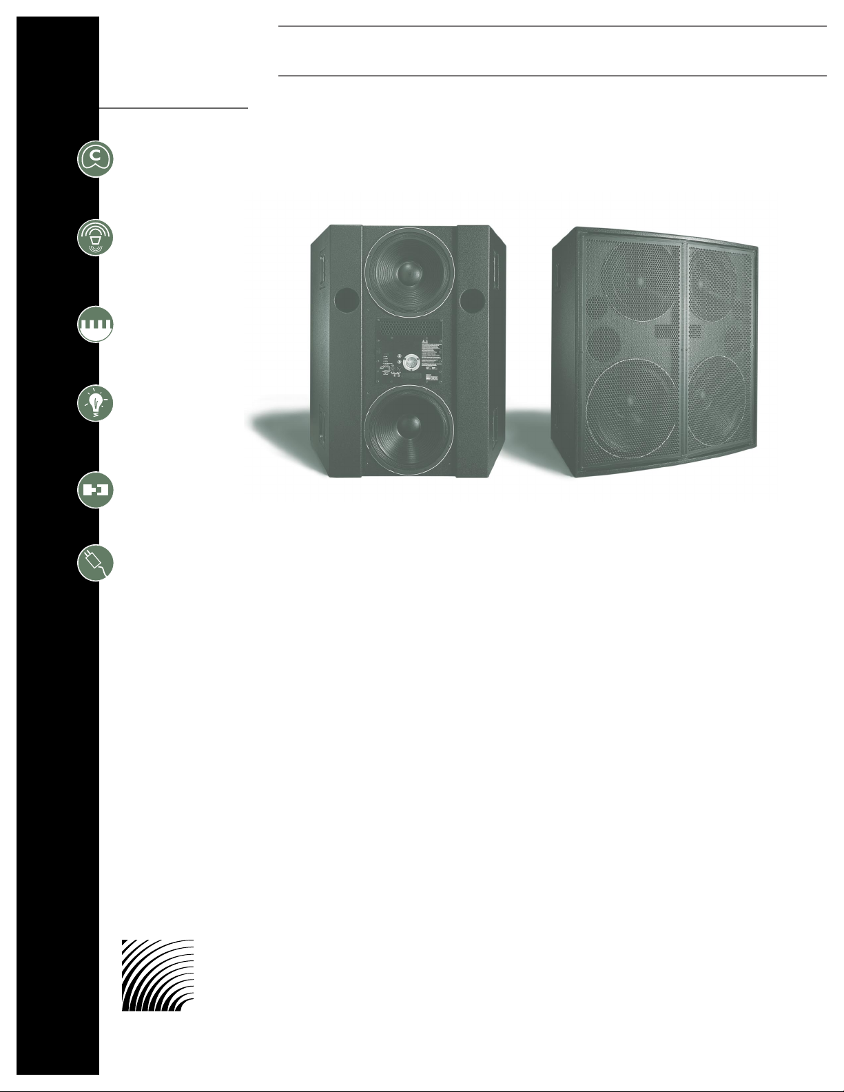
In an unprecedented
historical achievement, Meyer
Sound’s self-powered PSW-6
is the first subwoofer to
exhibit a true cardioid
coverage pattern throughout
its entire operating range.
This makes it the first
subwoofer to offer directional
control of low frequencies.
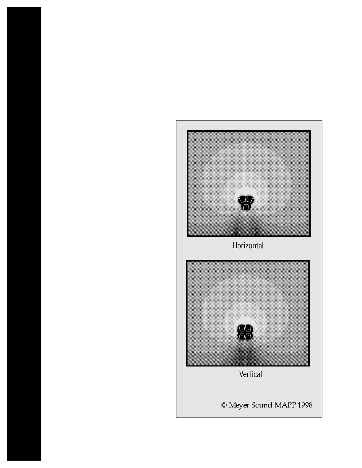
Covering more than two full
octaves, the PSW-6 has a
front to back SPL ratio of
more than 15dB, and
typically more than 20dB,
from 30 Hz to 125 Hz. The
horizontal and vertical
coverage patterns of the
PSW-6 are symmetrical,
ensuring consistent SPL and
frequency response
throughout the coverage
area.
FEATURES
directional steering as the
relationship between
transducers must be
consistent even while the
music changes in level. Nonlinearity or distortion above
a few percent would make
directional steering
impossible.
For nearly twenty years,
Meyer Sound has been
committed to developing
accurate, high-quality, linear
sound systems. As a result
of this continuing effort,
Meyer Sound has developed
powerful, low distortion
transducers unequaled in
their linear attributes.
The cardioid pattern refers
to the heart-shaped polar
pattern of the speaker (see
illustration next page).
Self-Powered Cardioid Subwoofer
PSW-6
Cardioid coverage
pattern
Front-to-back SPL
ratio of over 15 dB
Integrated control
electronics and
amplifiers
Intelligent AC
TM
System
Compatible with the
Remote Monitoring
System
TM
(RMS)
TruPower™
Limiting (TPL)
Meyer
Sound
Superior
engineering
for the art
and science
of sound.
Page 2
Sound pressure propagates from the
front of the speaker using four frontloaded cone drivers and is steered
away from the rear of the cabinet by
two rear-mounted cone drivers. This is
accomplished through a complex
electrical response relationship
between multiple amplifier channels
and critical geometry between the
front and rear transducers. This phase
relationship cancels low frequency
energy in the rear lobe and is additive
in the front, resulting in higher
efficiency and greater SPL.
Recent advancement in Meyer horn
technology has afforded precision
control of the coverage patterns of
mid and high frequency sound but
precise control of low frequency
coverage remained problematic due to
the enormous size of horns needed to
control low frequency sounds. To
achieve directional control of a
frequency, its wavelength must be less
than half the diameter of the horn. For
example, control of a 30 Hz tone
would require a horn 20 feet in
diameter. Similarly, any array of
subwoofers would have to cover a
similarly large area to achieve
directional control of low-frequency
sound.
The research which lead to the
development of the PSW-6 set out to
control low frequency sound in a
much smaller space for applications
where the size of large arrays were
impractical or impossible. Research
done using Meyer Sound’s own Source
Independent Measurement (SIM
®
),
and the Multipurpose Acoustical
Prediction Program (MAPP™) allowed
Meyer to create exceptionally accurate
computer models of low frequency
speaker interaction. Out of this
experimentation the PSW-6 was born.
The PSW-6 can be equipped to
operate with the Remote Monitoring
System (RMS
™
) network which
displays critical system data such as temperature, amplifier and driver
voltages, clipping and input polarity information on a Windows based PC
allowing the front-of-house mixer or system engineer to ensure proper
operation of the PSW-6 during performances.
Combining several PSW-6s in a line or arch array increases the power
potential of the system while maintaining the tight cardioid response
pattern. The PSW-6 can be incorporated into an MSL-4 or MSL-6
loudspeaker system with a standard LD-1A.
Page 3

Notes
Acoustical
(each loudspeaker)
Coverage
PSW-6 SPECIFICATIONS
Operating Frequency Range
Phase Response
Maximum SPL
Dynamic Range
30 Hz – 125 Hz (-6 dB points)
32 Hz - 100 Hz ± 3 dB
1
±50° 40 Hz – 130 Hz
2
140 dB @ 1 meter
3
>110 dB
Cardioid response pattern with >15 dB front-to-back ratio
See polar plot data below
1. Twenty-fourth-octave, half-space measurement.
2. From pure delay.
3. Peak, in half space.
specifications continued on next page
Page 4

T r ansducers
Amplifiers
Audio Input
AC Power
Physical
Notes
PHYSICAL DIMENSIONS
PSW-6 SPECIFICATIONS (cont’d)
Low Frequency
Type
Output Power
THD, IM, TIM
Type
Connector
Nominal Input Level
Connector
Automatic voltage selection
Opearional Voltage Range
Max Continuous RMS Current (
>10 s)
Max Burst RMS Current (<1 s)
Max Peak Current During Burst
Soft Start Turn-on
Dimensions
Weight
Enclosure/Finish
Rigging
Two 18” diameter 8Ω MS-818 cone drivers
Four 15” diameter 4Ω MS-415 cone drivers
Complementary power MOSFET output stages, class AB/H
2480 Watts (620 Watts / channel)
4
< .02 %
5 kΩ impedance, electronically balanced
XLR (A-3) male and female
+4 dBu (1.23 Vrms)
250V NEMA L6-20 (twistlock) inlet or IEC 309 male inlet
85 – 134 VAC and 165-264 VAC; 50 Hz / 60 Hz
Turn on: 85 VAC; Turn off: 134 VAC; 50/60 Hz
Turn on: 165 VAC; Turn off: 264 VAC; 50/60 Hz
115 V: 14 Arms 230 V: 7 Arms 100 V: 16 Arms
115 V: 26 Arms 230 V: 13 Arms 100 V: 30 Arms
115 V: 36 Apk 230 V: 18 Apk 100 V: 42 Apk
Inrush current <12 A @115 V
Height: 42.75”; Width: 42.52”; Length: 22.4”; Depth: 32.28”
442 lb (201 kg)
12-ply hardwood/black textured
Twelve pivoting lift rings (6 on top and bottom); working load for
each ring is 1500 lb with straight tensile pull. Safety factor is 5:1.
Entire cabinet is reinforced with steel girders
4. Nominal 8Ω resistive load, pink noise, 100V Peak.
ALL UNITS IN INCHES
Meyer Sound Laboratories, Inc.
2832 San Pablo Avenue
Berkeley, CA 94702
tel: 510.486.1166
fax: 510.486.8356
e-mail: techsupport@meyersound.com
http://www.meyersound.com
Meyer Sound Laboratories
has devoted itself to
designing, manufacturing,
and refining components
that deliver superb sonic
reproduction. Every part of
every component is
designed and built to
exacting specifications
and undergoes rigorous,
comprehensive testing
in the laboratories.
Research remains an
integral, driving force
behind all production.
Meyer strives for sound
quality that is predictable
and neutral over an
extended lifetime and
across an extended range.
Made by Meyer Sound, Berkeley, CA, USA
European Office:
Meyer Sound Germany
GmbH
Carl Zeiss Strasse 13
56751 Polch, Germany
© 1998 Meyer Sound Laboratories, Inc.
All rights reserved
3.1
26.9
14.0
32.3
29.4 Ref
C.G.
12.5
24.2
32.2
7.4
Top
1.6
(Rigging Typical, both ends)
Specifications subject to
change without notice
PSW-6 - 04.073.011.01
42.62
42.75
Front
(Without Grille Frame)
31.25
17.25
21.75
C.G.
Side
Rear
(Without Grille Frames)
ATENCIN: ACCESO INTERNO SOLO
AUTORIZADO A PERSONAL TCNICO CALIFICADO
ACHTUNG: GEHUSE NICHT FFNEN WARTUNG
UND REPARATUR NUR DURCH ELEKTROFACHKRFTE
ATTENTION: ENTRETIEN ET REPARATIONS
INTERNES NE SONT AUTORISEES QU’AU
PERSONNEL TECHNIQUE QUALIFI
UK WARNING: THIS APPARATUS MUST BE EARTHED.
NO OPERATOR SERVICEABLE PARTS INSIDE.
REFER SERVICING TO QUALIFIED PERSONNEL
WARNINGS:
THIS PRODUCT MUST BE GROUNDED
This surface may reach high temperatures while in use.
To ensure proper operation, allow at least 6 inches
clearance from this surface and adequate ventilation.
To reduce the risk of electric shock do not remove cover.
No operator serviceable parts inside.
Refer servicing to qualified personnel.
To reduce the risk of fire or electric shock
do not expose this appliance to rain or moisture.
!
Meyer Sound, Berkeley, CA. USA
1
2
3
1
3
2
Loop
Input
PUSH
Active / Speaker Fault
2 +
3 +
10K Ω
Balanced
Input Polarity
Front Exc
Rear TPL
Front TPL
Rear Exc
Network
Service
Wink
Reset
Activity
Remote Monitoring System
PSW-6
Earth / Chassis
1
Case
220K Ω
ESD
P
U
S
H
R
E
-
C
I
R
K
-
I
T
P
U
S
H
R
E
-
C
I
R
K
-
I
T
95-125V~
50-60Hz
1400W RMS MAX
208-235V~
50-60Hz
1400W RMS MAX
Auto-Voltage Select
UU
LL
CC
UU
LL
®®
LISTED
3K59
COMMERCIAL
AUDIO SYSTEM
 Loading...