

Page 1
HD-1
The HD-1 High Definition
Audio Monitor* is a self-contained,
precision loudspeaker for nearfield sound reproduction.
Aligned to closely approximate
a true point source radiator, the
HD-1 features exceptionally broad
directivity characteristics. Its time
delay response is tightly controlled,
with minimal deviation from linear
phase across the full frequency
range of its operation. Each unit is
individually factory-calibrated to
ensure unprecedented consistency
of performance. The HD-1 is
suitable for critical applications
ranging from professional recording to psychoacoustical research.
The HD-1 is a two-way system
comprising an 8-inch cone lowfrequency driver and dome tweeter
housed in a vented cabinet. The
low-frequency driver features an
exceptionally large magnet structure and a 2-inch voice coil for
greatest efficiency and heat dissipation. The tweeter employs a
specially-developed impregnated
silk dome to minimize breakup and
colorization.
Both drivers are of a proprietary
design, and are individually
selected for maximum linearity.
Their magnet structures employ
sophisticated field-cancelling
design techniques to minimize
magnetic field leakage, and the
cabinets may safely be placed
High Definition
Audio Monitor
within 2 feet of sensitive color
video monitors. For applications
requiring closer proximity to
monitors, an optional steelshielded model is available.
The HD-1 incorporates line-level
control electronics mounted within
a rear-panel chassis, including:
• an active balanced input circuit
with switchable sensitivity
(+4 dBu or -10 dBV);
• an active crossover utilizing
optimized pole-zero filter
combinations to achieve acousti-
cal transparency and linear
phase;
• independent protection circuits
for each loudspeaker driver;
• dual power amplifiers for
biamplification.
The driver protection circuits
employ thermo-predictive limiters
and soft peak clamps to guard
Operating Instructions
against damage from excessive
amplifier power and ensure
graceful overload characteristics.
Independent power biamplifiers
maximize system headroom,
efficiency and damping while
minimizing distortion. The low
frequency amplifier delivers 150
watts output power, while the high
frequency amplifier provides 75
watts. Both employ complementary
power MOSFET output stages
operating class A at low-to-moderate listening levels (<90 dB SPL),
and class AB at high levels.
The HD-1’s free-field frequency
response is flat within ±1 dB from
40 Hz to 20 kHz (-3 dB at 32 Hz
and 22 kHz). It delivers high peak
SPL with >100 dB dynamic range
and extremely low distortion.
Covers are included for use during
transport.
* patents pending
Meyer Sound Laboratories, Inc.
2832 San Pablo Avenue
Berkeley, California 94702
Page 2
Setup & Operation
High
Definition
Audio
HD-1
Monitor
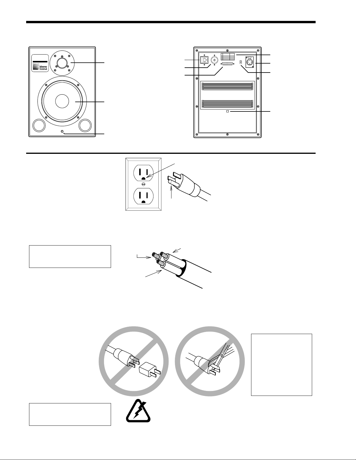
Locations of HD-1 Loudspeaker Components, Connectors and Controls
Dome tweeter
Cone low frequency driver
Indicator LED
IEC mains connector
and power switch
Voltage selector
switch
Calibration port
(factory use
only)
Voltage selection and
40
2
0
2
2
0
2
1
0
0
1
PUSH
fuse rating chart
Input connector
Input sensitivity
switch
Impact indicator
Power
• Set the voltage selector switch
before you connect and operate
the unit.
The HD-1 accepts AC voltages
from 90 to 260 VAC, at 50 or 60 Hz,
in four ranges. Select the range that
is closest to the local mains AC
voltage.
Do not switch among AC voltage
ranges with the power cable
connected to an outlet.
Fuse
The HD-1 is protected by a fast-
acting fuse in the voltage selector
switch.
• If the fuse blows, check the line
voltage and the voltage selector
setting.
• Always replace the fuse
with a component of
the same type and
rating.
Power Cable
• Connect the HD-1 to a
three-prong outlet.
Earth ground
Chassis ground
The HD-1 requires a grounded
outlet. Use a grounding adapter
when connecting to ungrounded
outlets.
Blue =
Neutral
Yellow/Green =
Earth Ground (Chassis)
Brown =
Hot
AC cable color code for wiring
international or special-purpose
power connectors
Placement
The HD-1 is designed for “near
field” operation. The best listening
distance is between 3 and 9 feet
from the speaker face.
The HD-1 is aligned for flat
frequency response in free field (no
adjacent boundary surfaces).
Placing it next to a wall or on the
floor will cause the low frequencies
to be exaggerated.
Nearby surfaces (such as a
mixing console control surface)
should be angled to minimize
reflections toward the listener.
For stereo playback systems,
speaker stands are highly recommended. Place them at least 3 feet
from any wall. In recording studios
the speakers may be placed on the
meter bridge.
When handling the
HD-1, avoid touching or
pressing on the dome
tweeter. If the dome
becomes dented, the
unit should be returned
for testing and
calibration
dome pops back into
position.
even if the
If the power cable appears frayed
or broken, replace it immediately
before operating the unit.
2
Never use ground-lifting
adapters. Do not cut the
AC cable ground pin.
• Always allow at least 6 inches
clearance behind the speaker for
cooling airflow.
Page 3

Input Connection
The HD-1 presents a 10 kohm
input impedance at a three-pin
XLR-type receptacle wired as
follows:
Pin 1 Audio common
Pin 2 Signal low (-)
Pin 3 Signal high (+)
Case Earth (AC) ground
Shorting any input connector pin
to the case may form a ground
loop and cause hum.
Standard audio cables with
XLR-type connectors may be used
for balanced signal sources. Unbalanced sources will require an inline adapter.
Troubleshooting
Sensitivity Switch
• For professional balanced
equipment, use the +4 dBu
setting.
• For semiprofessional and
consumer unbalanced equipment, use the -10 dBV setting.
Note that the -10 dBV setting is
more sensitive (designed for lower
signal levels) than the +4 dBu
setting:
• +4 dBu position:
1.23 VRMS = 114 dB SPL RMS
• -10 dBV position:
0.316 VRMS = 114 dB SPL RMS
Driving the HD-1 from a +4 dBu
source with the switch set to -10
dBV will result in increased noise.
Operation
In normal operation, the front-
panel LED will glow green.
At high listening levels, the LED
may flash red on program peaks.
This indicates the onset of overload, where the loudspeaker
protection limiters are activated.
If the LED is continuously red
for an extended period (8 hrs.),
thermal damage may result.
Calibration Port
The calibration port is for factory
use only. Do not apply external
voltages to any of the connector
pins.
Problem Symptom Possible Cause Action
No sound
not lit
Power switch on and lit, LED
out
Power switch on and lit, LED
lit
Distorted sound with hum
Selector switch setting correct
Low sound levels Insufficient drive from signal
Hiss Input sensitivity incorrectly set
Sensitivity setting correct
Program material OK
Bad AC connectionPower switch on but switch
Blown fuse
Signal source disconnected
AC voltage selector incorrectly set
Power brownout
source
Input sensitivity incorrectly set
Program material
Source equipment malfunction
Check AC outlet and power
cord.
Replace fuse. Check voltage
selector and AC line.
Check input cables, connectots and signal source.
Turn off HD-1. Check AC
outlet voltage and selector
switch setting.
Turn off HD-1. Check AC
outlet voltage; if low, contact
power company.
Increase source equipment
output level.
Set input sensitivity switch to
-10 dBV
Check sensitivity switch and
source equipment output.
Stop playback. If hiss
disappears, check program.
Unplug input connector. If
hiss disappears, check
source equipment.
Distorted or intermittent
sound
Input cables OK
Bad input connection
Defect in signal source
equipment
Check input cables
Substitute known good signal
source. If problem stops,
replace signal source
equipment.
3
Page 4

Obtaining Service
The HD-1 Monitor is protected
by Meyer Sound’s Limited OneYear Warranty. For complete
information regarding terms and
conditions, refer to the printed
warranty statement that is packed
with the system.
To extend coverage to two full
years, and assure notification of
product improvements or literature
updates, complete and mail the
enclosed Warranty Registration
Card.
Specifications
Acoustical - HD-1 System
Frequency Response
Free Field
Maximum SPL
Signal-to-Noise Ratio
Coverage Angle (-6 dB)
Audio Input
Type
Connector
Nominal Input Level
1
32 Hz to 22 kHz
-3 dB at 32 Hz and 22 kHz
±1 dB from 40 Hz to 20 kHz
125 dB SPL peak capability (120 dB @ 1 meter)
> 100 dB (noise floor 20 dBA @ 1 meter)
60 degrees horizontal and vertical
Electronically balanced, 10k ohms impedance
XLR (A-3) female
Accepts either +4 dBu or -10 dBV, switchable
To obtain service:
1) Contact your dealer or call
Meyer Sound.
2) If you are calling Meyer Sound,
have the serial number(s) of the
unit(s) at hand for reference. Ask
for Customer Service, and be
prepared to describe the problem clearly and completely.
3) If the problem cannot be resolved over the phone, you must
return the unit for service.
2
4) You will be given an RA (Return
Authorization) number for job
tracking. Refer to this number
on shipping materials and in all
correspondence concerning the
repair. Shipping charges are the
responsibility of the purchaser.
Any attempt to modify or replace
components of the HD-1 will
invalidate your warranty. Service
must
be performed by a Meyer
Sound service center.
Notes:
1. Subject to room loading. Specified for
8 feet actual distance between HD-1
cabinet and a single boundary
surface.
2. One-third octave resolution.
Unless otherwise specified, all acoustic
and magnetic measurements are
performed at one-half meter from front
baffle on tweeter axis.
Amplifiers
Type
Power Output
Low Frequency
High Frequency
THD, IM, TIM
Crossover
Transducers
Low Frequency
High Frequency
AC Power
Physical
Dimensions
Weight
Stray magnetic field
Complementary power MOSFET output stages
150 watts burst capability
75 watts burst capability
< .02 %
Optimized pole-zero filter combinations to
complement transducer response and to achieve
acoustical transparency and flat phase
8" diameter cone (2" voice coil)
1" dome tweeter (1" voice coil)
3-pin IEC male receptacle. Voltage selector switch
for 100/120/220/240 VAC, 50 or 60 Hz (accepts
voltages from 90 to 260 VAC)
16" H x 12" W x 14" D (+ 2" additional depth for
amplifier chassis and HF dome clearance)
51 lbs. (23 kg.)
<1 Gauss in all directions from cabinet
Physical Dimensions
12.00"
16.53"
15.65"
16.00"
14.00"
05.550.026.01 A2
Copyright © 1994, Meyer Sound Laboratories, Inc. All rights reserved.
9.20"
1.40"
13.20"5.00"
3.85"
1.40"
4
 Loading...