

Page 1
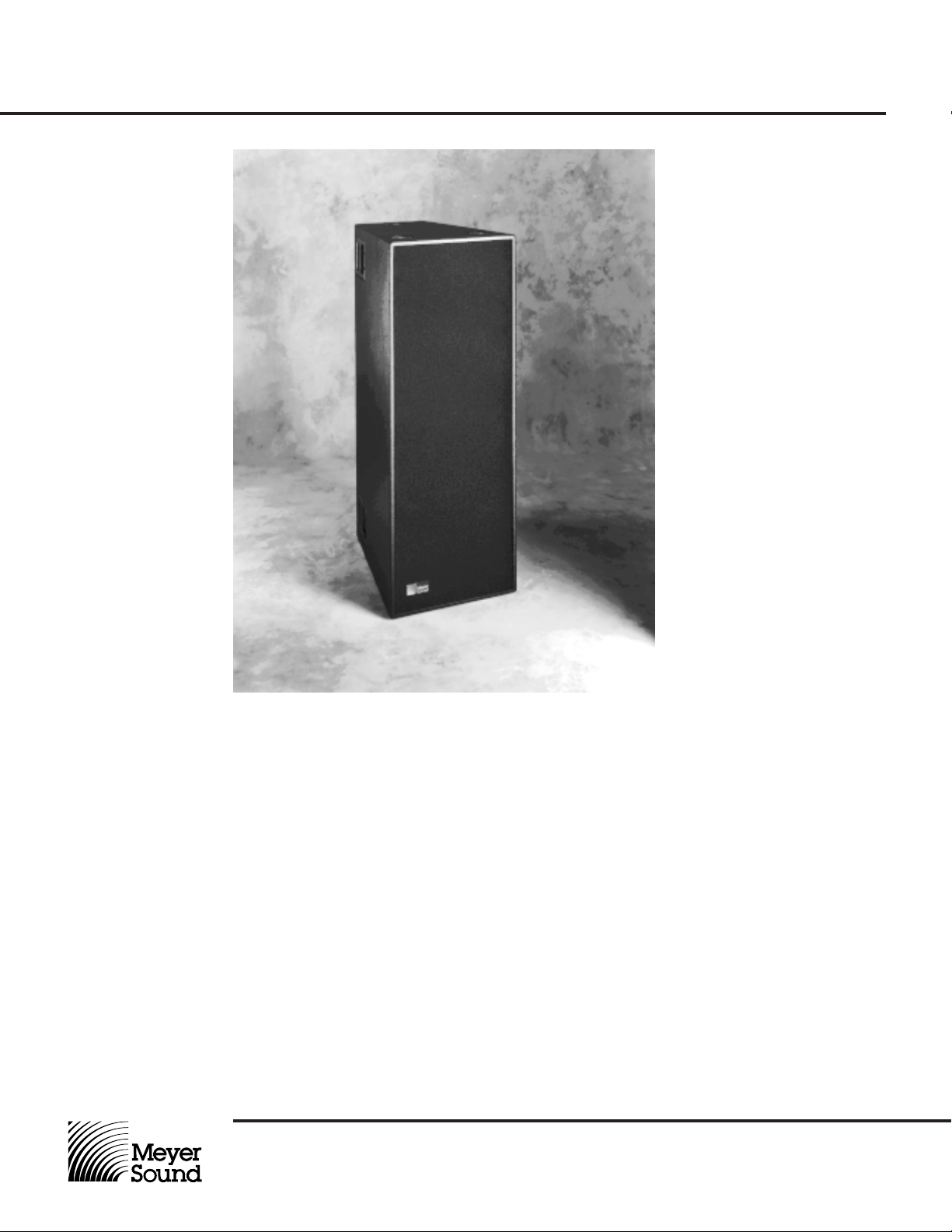
DS-2
Mid-Bass
Loudspeaker
Operating Instructions
The DS-2 is a high-power, arrayable mid-bass loudspeaker designed to supplement Meyer Sound rein–
forcement systems in the 50-160 Hz range. The system utilizes two proprietary 15-inch cone drivers in a
folded horn enclosure braced with steel vertical reinforcing rods. The horn features a hyperbolic flare for
maximum energy transfer with minimum frequency
response ripple. Its balanced compression chamber
presents a symmetrical load to the drivers, providing
very high power handling and low distortion.
Meyer Sound Laboratories, Inc.
2832 San Pablo Avenue
Berkeley, CA 94702
The DS-2 is designed to operate as a system with the
D-2 Control Electronics Unit. The D-2 comprises an
electronic crossover, Meyer Sound exclusive
SpeakerSense™ driver protection circuitry, and amplitude and phase response correction circuitry optimized for the DS-2. A switch-defeatable crossover
and line-level output to drive subwoofer systems is
provided, with a preset-panel sub polarity switch to
facilitate aligning the subwoofers with the main system.
Page 2

DS-2
Mid-Bass
Loudspeaker
Operating Instructions
Amplifier
Requirements
Connections
Verifying System
Polarity
The DS-2 requires a professional-quality power amplifier
capable of delivering 600-1100 watts continuously into
4 ohms, with a maximum output voltage swing of
140 Vpk and voltage gain of 14 dB (minimum) to 32 dB
(maximum).
The connection terminals of each 15-inch cone driver appear separately on a single Cannon P-type 4-pin connector (5-pin in Europe) located on the rear of the DS-2 cabinet. The pin assignments for this connector are:
Pin 1—Driver 2 common
Pin 2—Driver 1 common
Pin 3—Driver 1 hot
Pin 4—Driver 2 hot
Pin 5—No connection (Europe only)
These connections must be brought back separately to
the power amplifier and wired in parallel at its output. The
minimum wire size for connections between the DS-2 and
the power amplifier is 14 gauge (12 gauge for runs
greater than 100 feet).
All Meyer Sound Ioudspeaker systems are thoroughly
tested in aII stages of manufacture and the correct polarity of individual cabinets is assured. Polarity reversals
may occur at many other points in the system, however.
A single DS-2 cabinet or component that is out of polarity
with the rest of the system will cause cancellations, resulting in a noticeable decrease in SPL and the possibility
of component damage.
In part because oI the signal processing circuitry in the
D-2 Control Electronics Unit, “phase-popper” speaker
checkers cannot reIiably test for correct polarity of the
DS-2. It is a simple matter to verify individuaI cabinets,
and test for correct polarity between cabinets, using a
spectrum analyzer (1⁄3rd octave minimum frequency resolution) with a pink noise source.
Note. A polarity reversal within the DS-2 system can result in severe damage to the drivers. lt is strongly recommended that polarity testing be done at Iow Ievels and
with the appropriate equipment.
1. Single cabinets
• Disconnect one of the two DS-2 drivers at the amplifier output.
• Set the D-2 Level control at minimum and connect the
pink noise source to its input, then advance the D-2
Level control to a comfortable level.
The use of an amplifier rated significantly less than
600 watts will reduce the system headroom. Conversely,
using an amplifier with greater than 140 Vpk output swing
may endanger the loudspeaker, and is not recom-
mended.
Note: If you are using standard Meyer Sound loud–
speaker cables and adapters, simply connect the female
end of the loudspeaker cable to the DS-2, the male end
of the cable to the pigtail adapter P connector, and the
dual banana connector of the adapter to the amplifier output.
If you are constructing your own cables, be certain to
verify that the DS-2 drivers are wired in correct polarity at
the amplifier output. If the drivers are out of polarity and
the system is driven to high amplifier power levels, the
components will be destroyed.
For connections between the D-2 Control Electronics Unit
and the power amplifier, refer to the D-2 Operating In-
structions.
• Reconnect the second DS-2 driver at the amplifier
output. The noise volume level should double.
• If the noise level decreases, the second driver is out
of polarity with the first.
2. Multiple cabinet arrays – Each cabinet should first be
tested individually.
• Connect one DS-2, set the D-2 Level control at minimum and connect the pink noise source to its input,
then advance the D-2 Level control.
• Position the measurement microphone on the axis between two adjacent DS-2 cabinets, and about 6 feet
distant. Note the frequency response and overall
level.
• Leaving the first cabinet connected, connect the adjacent one and observe the analyzer display. The entire
curve should rise in level by approximately 6 dB, indicating correct addition between the Ioudspeakers. A
polarity reversal between the Ioudspeakers wiII show
up as severe cancellations.
• SimiIarIy, connect the rest of the cabinets in the array
one by one, Iooking for correct addition as each loudspeaker is connected. (It will be necessary to reposition the microphone.)
Meyer Sound Laboratories, Inc.
2832 San Pablo Avenue
Berkeley, CA 94702
Page 3

DS-2
Mid-Bass
Loudspeaker
Operating Instructions
3. Crossover to main system – All cabinets in the DS-2
array and main system should first be tested, then placed
in the position in which they will be operated.
• With the system master level control at minimum, input pink noise to the system, then set a comfortable
measuring level. Position the microphone on the axis
of the system, 6 feet or more distant.
• Note the system response in the mid-bass region. A
cancellation of approximately 6 dB centered at 160 Hz
indicates a polarity reversal between the DS-2’s and
the main system.
• If in doubt, reverse the polarity of the DS-2’s and observe the response.
4. Crossover to subwoofers (optional) – If you elect to
use subwoofers to reproduce the 30-60 Hz octave, they
must first be tested individually for correct polarity (refer
to the Operating Instructions for the subwoofer system).
It is common to place subwoofers at some distance from
the main system (on the ground below a flown array, for
example). In part because of the long wavelengths involved, propagation delay can cause a cancellation at the
crossover to the main system. For this reason, it is always necessary to check the subwoofer crossover once
the system has been installed in the position in which it
will be operated.
• Connect the subwoofer system input to the D-2 Subwoofer output, and set the D-2 Mode switch to the
“DS-2 & Sub” position (refer to the D-2 Operating
Instructions).
• With the system master level control at minimum, input pink noise to the system, then set a comfortable
measuring level. Position the measurement microphone on the axis between the subwoofers and the
system, 6 feet or more distant.
• Note the system response in the bass region. A cancellation of approximately 6 dB centered at 50 Hz indicates a polarity reversal between the subwoofers and
the main system.
• If in doubt, reverse the subwoofer polarity using the
D-2 Sub Polarity switch and observe the response.
Placement and
Arraying
The DS-2 is designed to perform extremely well in arrays
with Meyer Sound MSL-3A‘s or MSL-10A‘s, and maintains a well-defined 1/R image at the rear of the cabinet.
Its rigging points are strengthened with steel reinforcing
rods running the length of the cabinet from top to bottom,
and a single DS-2 will support two MSL-3A or DS-2 cabinets suspended below it.
The diagrams below illustrate some examples of DS-2 arrays. Where units are arrayed in a single block, they
should always be placed with adjacent cabinet faces
A. Minimum
configuration
B. Block of
four units
flush to one another. Spreading the cabinets does not
substantially alter the horizontal coverage of the array because of the long wavelengths involved.
Until the array reaches large dimensions (six or more
tight-packed cabinets), horizontal coverage remains a
constant 120° (±60°) as units are added to the array
(acoustic power increases substantially with each additional cabinet). In arrays with MSL-3A’s, large array size
may be achieved by interleaving DS-2’s and MSL-3A’s
as shown in Diagram C.
C. Interleaved with
MSL-3A cabinets
Meyer Sound Laboratories, Inc.
2832 San Pablo Avenue
Berkeley, CA 94702
D. Arrayed with
MSL-10A cabinets
Page 4

DS-2
Mid-Bass
Loudspeaker
Operating Instructions
Specifications
Acoustical – DS-2 / D-2 System
Frequency response
Maximum SPL
2
3
1
50-160 Hz ± 3 dB
Continuous 136 dB
Peak 148 dB
Sensitivity
4
112 dB
Coverage (-6dB points)
Horizontal 120 degrees
Vertical 120 degrees
DS-2 Loudspeaker
Transducers (2) MS-15 15-inch cone driver
Impedance
Nominal 4 ohms
Minimum 3.5 ohms real part, 0 ohms imaginary part, at 80 Hz
Maximum Safe Amplifier Swing 140 Vpk
Enclosure Folded horn, multi-ply Finnish birch
Finish Black textured or charcoal-grey carpet (optional)
Physical Dimensions 21
1
⁄4" W x 563⁄4" H x 30" D
Weight 250 lbs (113.6 kg)
Protective Grill Expanded metal screen frame, vinyl damped,
charcoal-grey foam covering
Connector Cannon EP-4 male, EP-5 male (Europe only)
Rigging Aircraft pan fittings
Note 1:
Acoustical specifications are for the minimum configuration of two DS-2 cabinets, and are measured on axis at 2 meters from 1/R image (located at cabinet rear).
Note 2:
Half-space conditions, pink noise input, in third-octave bands.
Note 3:
Loudspeakers driven with pink noise (peak-to-RMS ratio
≈
12 dB), with amplifier rated at 600 W/
channel at 4 ohms. The DS-2 will accommodate amplifiers capable of peak output levels up to
±
140 Vpk.
Note 4:
Loudspeakers driven at 2 vrms each (1 watt @ 4 ohms each).
© 1991 Meyer Sound 05.058.010.01A
Meyer Sound Laboratories, Inc.
2832 San Pablo Avenue
Berkeley, CA 94702
 Loading...