

Page 1
DATASHEET LF
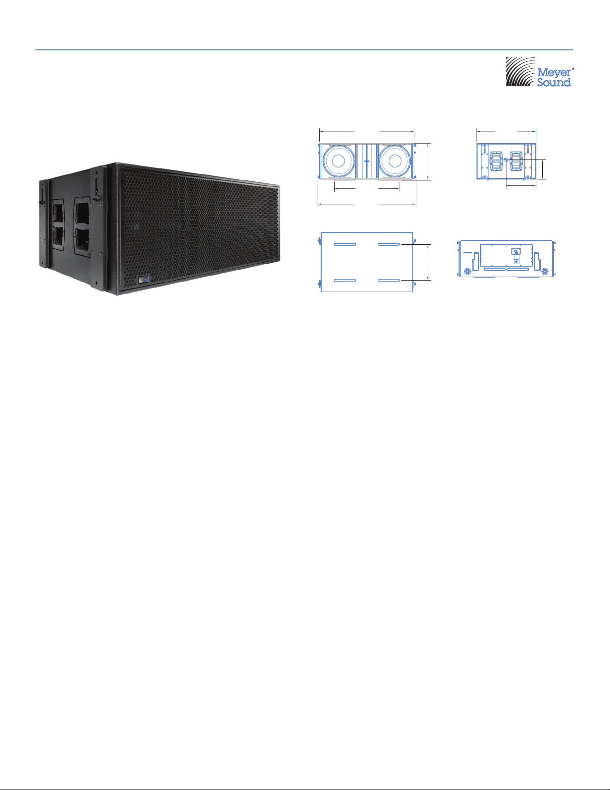
1100-LFC Low‑Frequency Control Element
52.60
[1336 mm]
20.48
[520 mm]
36.00
[914 mm]
54.65
[1388 mm]
20.10
[511 mm]
(Shown with optional Quickfly® rigging) (Dimensions shown for Rigging version)
The 1100‑LFC low‑frequency control element is a self‑powered
loudspeaker defined by its sonic linearity in reproducing low‑
MeyerSound tunes and vents the cabinet to specifically optimize
it for low air velocities.
frequency transients at high continuous output levels with very
low distortion. This ultra‑low distortion, coupled with exceptional
headroom and optimized rigging options, makes the 1100‑LFC
a flexible tool for low‑end directional applications for large‑scale
tours and installations.
The optional MRK‑1100 rigging kit, available as a factory‑installed
option or field upgrade, includes captive GuideALinks
allow the loudspeaker to be flown from the MTG‑1100 top grid.
Convenient pinned handles and slots make the GuideALinks,
located at the front and rear of the cabinet, easy to set. The
To guarantee optimum performance, design 1100‑LFC systems
with Meyer Sound’s MAPP
™
system design tool. This intuitive,
GuideALinks also accommodate reversed units for flown cardioid
arrays.
cross‑platform application accurately predicts directional
patterns, frequency and impulse responses, and linear peak SPL
for 1100‑LFC systems, ensuring that systems deliver the required
coverage and SPL.
Suspend line arrays comprising up to 16 cabinets at a 5:1 safety
factor and BGC V1 from the optional MTG‑1100 top grid. For
touring and portable systems, the optional MCF‑1100 caster frame
accommodates three‑cabinet stacking of the 1100‑LFC for secure
An optimally tuned, vented cabinet houses the 1100‑LFC’s two
18‑inch, long‑excursion cone drivers. The loudspeaker’s 28Hz to
100Hz operating frequency range complements LEO
™
LYON
, JM‑1P, and other Meyer Sound loudspeakers, allowing it
®
, LEOPARD™,
to integrate seamlessly with line arrays and curvilinear arrays.
travel. Optionally available durable nylon covers, accommodating
stacks of two or three 1100‑LFCs, ensure complete road‑readiness.
Meyer Sound’s RMS
™
remote monitoring system comes standard
with all 1100‑LFCs and provides comprehensive monitoring of
system parameters from a host computer running Compass
The unit’s power amplifier operates at voltages from
208 to 235 V AC, at 50/60 Hz. TruPower
®
limiting ensures
maximum driver protection, minimizing power compression while
yielding high constant output under high continuous and peak
control software via the RMS
connectors allow the use of composite cables carrying both
balanced audio and RMS signals (3‑pin XLR audio connectors are
optionally available).
™
interface. Convenient 5‑pin XLR
power conditions. A single, field‑replaceable module located on
the rear of the cabinet contains the amplifier, control electronics,
and power supply.
Meyer Sound constructs the 1100‑LFC cabinet with premium
multi‑ply birch and coats it with a slightly textured black finish.
A powder‑coated, hex‑stamped steel grille with acoustical black
The 1100‑LFC cabinet includes protective plastic skids on the
bottom that securely align with the cabinet’s top slots. Units
are stackable normally or reversed for cardioid configurations.
mesh protects the unit’s drivers. Other options include weather
protection and custom color finishes for fixed installations and
applications with specific cosmetic requirements.
33.00
[838 mm]
16.65
[423 mm]
10.65
[270 mm]
™
that
®
Page 2
FEATURES AND BENEFITS
• High peak power output with low‑frequency clarity and excellent transient reproduction at extreme levels
• Linearity ensures low‑frequency output with consistent directional properties in a variety of configurations at any level
• Tuned, vented cabinet optimized for low air velocities
• Stackable and flyable in regular and cardioid arrays
• Seamlessly integrates with LEO, LYON, LEOPARD, and other Meyer Sound loudspeakers
APPLICATIONS
• Stadiums
• Arenas
• Concert halls
• High‑power, controlled‑directivity arrays
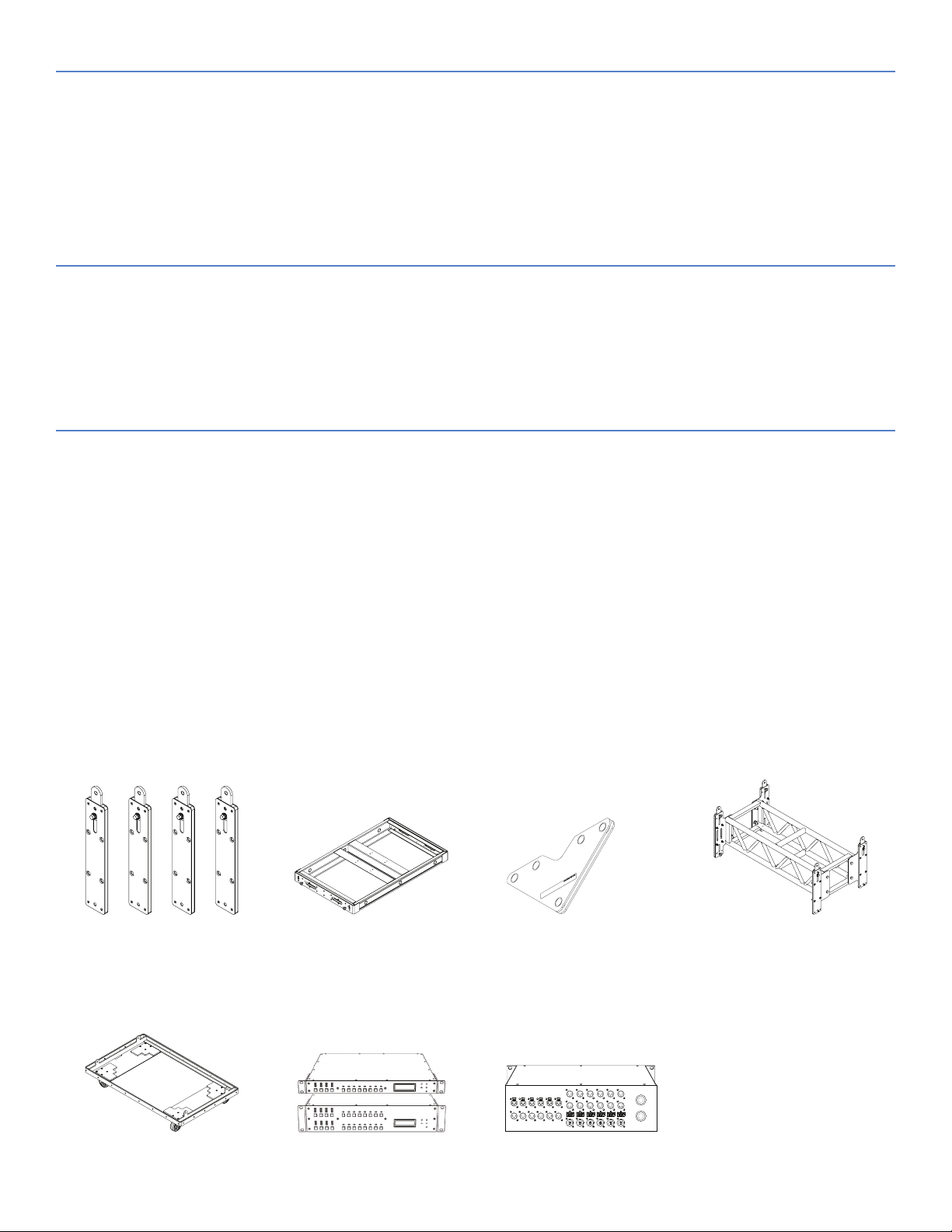
ACCESSORIES AND ASSOCIATED PRODUCTS
MRK-1100 Rigging Kit: Allows the 1100‑LFC to be flown from the MTG‑1100 grid; includes four captive GuideALinks and eight quick‑release pins.
MTG-1100 Top Grid: With some restrictions, flies up to 16 1100‑LFCs at a 5:1 safety factor and BGV C1; accommodates a variety of pickup
configurations with six pickup points; includes attachment points to accommodate brackets and adapters for lasers and inclinometers. Always use
MAPP to verify rigging load ratings.
MVP Motor Vee Plate: Fine tunes the horizontal aim of arrays; compatible with MTG‑LEO‑M, MTG‑LYON, MTG‑1100, and MG‑LEOPARD/900 grids.
MAS-1100 Array Spacer: Placed between cabinets in 1100‑LFC arrays to lengthen the array and improve vertical directionality; includes four captive
GuideALinks and eight quick‑release pins.
MCF-1100 Caster Frame: Safely transports up to three 1100‑LFC cabinets, making it easy to assemble and disassemble arrays in blocks of three
cabinets. (The MCF‑1100 does not include quick‑release pins, because it is secured with the quick‑release pins included with the loudspeaker.)
Galileo GALAXY Network Platform: The Galileo GALAXY Network Platform provides state‑of‑the‑art audio control technology for loudspeaker
systems with multiple zones. With immaculate sonic performance, it provides a powerful tool set for corrective room equalization and creative fine‑
tuning for a full range of applications. In addition, GALAXY devices’ improved Delay Integration lets you combine 1100‑LFCs with different Meyer
Sound loudspeakers.
MDM-5000 Distribution Module: MDM‑5000 units conveniently power 1100‑LFC systems, routing up to six channels of AC power, balanced audio
and RMS signals to the loudspeakers.
MRK-1100 Rigging Kit MTG-1100 Top Grid MVP Motor Vee Plate MAS-1100 Array Spacer
MCF-1100 Caster Frame Galileo GALAXY Network
Platform
MDM-5000 Distribution Module
Page 3

SPECIFICATIONS
ACOUSTICAL
1
COVERAGE
TRANSDUCERS
AUDIO INPUT
Operating Frequency Range228 Hz – 100 Hz
Frequency Response
3
30 Hz – 85 Hz ±4 dB
Phase Response 34 Hz – 82 Hz ±30°
Linear Peak SPL
4
140 dB with crest factor >9.5 dB (M-noise), 140 dB (Pink noise), 141 dB (B‑noise)
360° (single unit); varies with number of units and configuration
Low Frequency Two 18‑inch long‑excursion cone drivers; 8Ω nominal impedance
Type Differential, electronically balanced
Maximum Common Mode Range ±15 V DC, clamped to earth for voltage transient protection
XLR 5‑pin female input with male loop output; XLR 3‑pin female connectors available to
Connectors
4
accommodate only balanced audio (no RMS signals)
Input Impedance 10 kΩ differential between pins 2 and 3
Pin 1: Chassis/earth through 220 kΩ, 1000 pF, 15 V clamp network to provide virtual ground lift at
audio frequencies
Pin 2: Signal +
5
Wiring
Pin 3: Signal –
Pin 4: RMS
Pin 5: RMS
Case: Earth ground and chassis
AMPLIFIER
AC POWER
CURRENT DRAW
Maximum Long‑Term Continuous Current (>10 sec) 10.5 A rms (230 V AC)
Nominal Input Sensitivity 0 dBV (1.0 V rms) continuous is typically the onset of limiting for noise and music
Input Level
Audio source must be capable of producing of +20 dBV (10 V rms) into 600 Ω to produce the
maximum peak SPL over the operating bandwidth of the loudspeaker
Type 2‑channel complementary MOSFET output stages (Class AB/H bridged)
Total Output Power
6
8100 W peak
THD, IM, TIM < 0.02%
Cooling Three ultra high‑speed primary fans; three ultra high‑speed reserve fans
Connectors PowerCon32
Automatic Voltage Selection 208–235 V AC, 50/60 Hz
Safety Rated Voltage Range 208–235 V AC, 50/60 Hz
Turn‑on and Turn‑off Points 165 V AC turn‑on; 264 V AC turn‑off
Idle Current 0.6 A rms (230 V AC)
Burst Current (<1 sec)
7
18 A rms (230 V AC)
Maximum Instantaneous Peak Current 53 A peak (230 V AC)
RMS NETWORK
Inrush Current < 30 A peak
Equipped with two‑conductor twisted‑pair network, reporting all operating parameters of amplifiers to
system operator’s host computer.
Page 4

SPECIFICATIONS, CONT’D.
PHYSICAL
Dimensions without Rigging W: 52.60 in (1336 mm) x H: 20.48 in (520 mm) x D: 33.00 in (838 mm)
Dimensions with Rigging W: 54.65 in (1388 mm) x H: 20.48 in (520 mm ) x D: 33.00 in (838 mm)
Weight without Rigging 249 lb (112.9 kg)
Weight with Rigging 285 lb (129.3 kg)
Enclosure Premium multi‑ply birch with slightly textured black finish
Protective Grille Powder‑coated, hex‑stamped steel with acoustical black mesh
Rigging
Optional MRK‑1100 rigging kit with captive GuideALinks secured with 0.5 in x 1.25 in quick release
pins for ground‑stacked, flown, and cardioid configurations
NOTES
1. Loudspeaker system predictions for coverage and SPL are available in Meyer Sound's MAPP System Design Tool.
2. Recommended maximum operating frequency range. Response depends on loading conditions and room acoustics.
3. Measured in half‑space with pink noise at 4 m, 1/3‑octave frequency resolution.
4. Linear Peak SPL is measured in half‑space at 4 m referred to 1 m. Loudspeaker SPL compression measured with M‑noise at the onset of
limiting, 2‑hour duration, and 50‑degree C ambient temperature is < 2 dB.
M-noise is a full bandwidth, (10 Hz–22.5 kHz) test signal developed by Meyer Sound to better measure the loudspeaker’s music performance.
It has a constant instantaneous peak level in octave bands, a crest factor that increases with frequency, and a full bandwidth Peak to RMS
ratio of 18 dB. The presence of a greater‑than (>) symbol with regard to crest factor indicates it may be higher depending on EQ and boundary
loading.
Pink noise is a full bandwidth test signal with Peak to RMS ratio of 12.5 dB.
B-noise is a Meyer Sound test signal used to ensure measurements reflect system behavior when reproducing the most common input spectrum,
and to verify there is still headroom over pink noise.
5. Pins 4 and 5 (RMS) only included with XLR 5‑pin connector that accommodates both balanced audio and RMS signals.
6. Peak power based on the maximum unclipped voltage the amplifier will produce into the nominal load impedance.
7. AC power cabling must be of sufficient gauge so that under burst current rms conditions, cable transmission losses do not cause the
loudspeaker’s voltage to drop below the specified operating range.
ARCHITECTURAL SPECIFICATIONS
The loudspeaker shall be a linear, low‑distortion, self‑powered,
low‑frequency control element and shall be capable of flown and
groundstacked configurations. Its transducers shall include two 18‑inch
long‑excursion cone drivers.
The loudspeaker shall incorporate internal processing and a 2‑channel
Class AB/H amplifier with complementary MOSFET output stages.
Protection circuits shall include TruPower limiting. The audio input shall
be electronically balanced with a 10
0dBV (1.0V rms) signal (+20dBV to produce maximum peak SPL).
Audio connectors shall be 5‑pin XLR, female and male; 3‑pin XLR audio
connectors shall be optionally available.
Performance specifications for a typical production unit shall be as follows,
measured at 1/3‑octave resolution: operating frequency range shall be
28–100 Hz; frequency response shall be 30–85Hz ±4dB, measured in
half‑space with pink noise at 4 m, 1/3‑octave frequency resolution; phase
response shall be 34–82Hz ±30degrees; Linear Peak SPL shall be 140dB
with crest factor >9.5 dB, measured in half‑space with M‑noise at 4 m
referred to 1 m.
Meyer Sound Laboratories, Inc.
2832 San Pablo Avenue
Berkeley, CA 94702
kΩ impedance and accept a nominal
+1 510 486.1166
www.meyersound.com/contact
www.meyersound.com
The internal power supply shall perform EMI filtering, soft current turn‑on,
and surge suppression. Power requirements shall be nominal 230V AC
line current at 50or 60Hz. UL and CE operating voltage range shall be
208 to 235VAC. Current draw during burst shall be 18A rms at 230VAC.
Current inrush during soft turn‑on shall not exceed 30 A at 230 V AC.
The AC power connector shall be a PowerCon32. The loudspeaker shall
include the RMS remote monitoring system module.
Components shall be mounted in an optimally tuned, vented enclosure
constructed of premium multi‑ply birch and coated with a slightly textured
black finish.
Dimensions shall be 52.60 in (1336 mm) wide x 20.48 in (520 mm)high x
33.00 in (838 mm)deep. Dimension with optional rigging shall be 54.65in
(1388 mm) wide x 20.48 in (520 mm ) high x 33.00 in (838 mm) deep.
Weight shall be 249lb(112.9kg). Weight with optional rigging shall be
285lb (129.3kg).
The loudspeaker shall be the Meyer Sound 1100‑LFC.
1100-LFC
04.220.004.02 B3
Copyright © 2019. All Rights Reserved.
 Loading...