

Page 1
INSTRUCTION AND PARTS BOOK
FOR
MODELS 526, 2900, & 4000
Installation must be made in accordance with local and state codes which
may differ from manual. Save these instructions.
WOOD/COAL FURNACES
07/97
Phone 715/654-5132
Fax 715/654-5513
Page 2
INTRODUCTION
Dear Woodchuck Owner,
Congratulations on your purchase of a Woodchuck heating appliance. Un
doubtedly you have given much consideration to your purchase and we’re
proud that you have selected a Woodchuck. Pride in craftsmanship and engi
neering have made your Woodchuck the finest heating appliance available to
day.
Solid fuels are abundant and inexpensive. Wood is our only renewable
source of fuel and conservative estimates put our coal reserves at 800 years.
Our dual fuel units provide the savings and comfort of solid fuels and the con
venience of electric heat in one attractive package.
There is no substitute for quality. That is why thousands of people like you
have purchased a Woodchuck. They also felt it was the best equipment to
serve their heating needs, now and in years to come. We ask that you follow
our policy of “safety first” and we strongly suggest that you read through the
owner’s manual before installing and operating your furnace.
For a lifetime of satisfaction, thank you for not compromising with quality.
Sincerely,
Donald A. Meyer
President
MEYER MANUFACTURING CORP.
-
-
-
-
We are constantly improving and updating our product in order to provide the
highest quality and value possible. Consequently pictures might sometimes dif
fer slightly from the actual product.
-
TRANSPORTATION DAMAGES
Before reading this manual and proceeding with the installation, inspect your new Woodchuck to make sure there
were no shipping damages. If you find there have been damages incurred, call your dealer immediately. He will
then take a course of action to correct the problem.
2
Page 3

TABLE OF CONTENTS
Page
Introduction..........................................................................................................................................................2
Table of Contents ................................................................................................................................................3
Furnace Safety ....................................................................................................................................................4
Specifications ......................................................................................................................................................5
General Information.............................................................................................................................................6
High Quality Construction ................................................................................................................................6
Efficiency .........................................................................................................................................................6
Comfort ............................................................................................................................................................6
Additional Comfort And Saving........................................................................................................................7
Operation.............................................................................................................................................................8
Common Sense ...............................................................................................................................................8
! If You Have Chimney Fire !............................................................................................................................8
! Important ! Operation Procedure In The Event of Power Failure ..................................................................8
Operating Your Woodchuck Furnace ..............................................................................................................9
Startup..........................................................................................................................................................9
Burning Wood In Your Woodchuck..................................................................................................................9
Helpful Hints...............................................................................................................................................10
Ash Removal..............................................................................................................................................10
Burning Coal In Your Woodchuck..................................................................................................................11
Starting A Coal Fire....................................................................................................................................11
Recharging.................................................................................................................................................11
Banking ......................................................................................................................................................11
Bituminous Recharging ..............................................................................................................................11
Helpful Hints...............................................................................................................................................11
Ash Removal..............................................................................................................................................12
Maintenance......................................................................................................................................................12
Trouble Shooting ...............................................................................................................................................13
Installation .........................................................................................................................................................15
General Requirements...................................................................................................................................15
Placement And Minimum Clearances............................................................................................................15
Chimney Installation ......................................................................................................................................17
Installing Your Woodchuck ............................................................................................................................18
Stove Pipe Installation ...................................................................................................................................18
Installation Of A Barometric Draft ..................................................................................................................18
Air Duct Installation........................................................................................................................................19
Woodchuck Final Assembly...........................................................................................................................20
Optional Shaker Grate Installation-Model 526 ...........................................................................................20
Install Shaker Grate Handle, Model 2900 Only..........................................................................................21
Install Firebrick ...........................................................................................................................................22
Install Optional Catalytic Combustor ..........................................................................................................22
Assemble Manual Draft-Model 526 Only ...................................................................................................23
Install Comfort Control Center And Forced Draft Blower ...........................................................................23
Install Circulating Blower............................................................................................................................24
Assemble Filter Box ...................................................................................................................................24
Electrical Hookup .......................................................................................................................................25
Repair Parts ......................................................................................................................................................27
3
Page 4

FURNACE SAFETY
THERE ARE INHERENT HAZARDS ASSOCIATED WITH THE OPERATION OF WOOD/COAL FURNACES. FOR
YOUR SAFETY READ, UNDERSTAND, AND HEED THE FOLLOWING:
DANGER:
RISK OF FIRE OR EXPLOSION. DO NOT BURN GARBAGE, GASOLINE, DRAIN OIL, OR OTHER FLAMMABLE
LIQUIDS. FAILURE TO HEED MAY RESULT IN SERIOUS PERSONAL INJURY OR DEATH.
DANGER:
NEVER USE CHEMICALS OR FLUIDS SUCH AS GASOLINE, CHARCOAL LIGHTER FLUID, DRAIN OIL, FUEL
OIL OR KEROSENE TO LIGHT A FIRE IN YOUR WOODCHUCK. FAILURE TO HEED MAY RESULT IN SERIOUS
PERSONAL INJURY OR DEATH.
DANGER:
DURING OPERATION, LOADING AND ASH DOORS, AND EXPOSED FIREBOX ARE EXTREMELY HOT. NEVER
TOUCH THESE PARTS WHEN HOT. FAILURE TO HEED MAY RESULT IN SERIOUS PERSONAL INJURY.
CAUTION:
· Risk Of Fire
· Do Not Operate With Fuel Loading Or Ash Removal Doors Open.
· Do Not Store Fuel Or Other Combustible Material Within Marked Installation Clearances.
· Under Certain Conditions Of Use, Creosote Buildup May Occur Rapidly. Inspect And Clean Flues And Chimney
Regularly.
· Wait 10 Seconds On First Latch Before Refueling. Opening Loading Door Rapidly Can Cause A Flame To Flash
Out The Door. Use Caution When Opening Loading Door.
· Unsafe To Load Coal Above Top Of Brick.
· Keep Ash Pan Out Of Unit During Operation. Ash Pan Can Get Very Hot.
· Ash Can Must Be Placed On A Noncombustible Surface.
· Never Use Anything But An Air Tight Metal Container To Dump Your Ashes In. Every Year Many Fires Are
Caused By Emptying Ashes Into Cardboard Boxes Or Paper Bags.
·
Proven Fact - Small Red Embers Buried In Ash Cans Stay Red Hot For Days. Ashes Are A Good Thermal Insu
lator And Keep Enough Oxygen Away So Embers Do Not Burn Out.
-
THERE ARE ADDITIONAL HAZARDS ASSOCIATED WITH IMPROPER INSTALLATION OF WOOD/COAL FUR
NACES AND WITH SERVICE AND MAINTENANCE OF WOOD/COAL FURNACES. FOR YOUR SAFETY READ,
UNDERSTAND, AND HEED THE FOLLOWING:
WARNING:
DISCONNECT APPLIANCE FROM ELECTRICAL SUPPLY BEFORE SERVICING UNIT. FAILURE TO HEED MAY
RESULT IN SERIOUS PERSONAL INJURY OR DEATH.
CAUTION:
·
Equipment Must Be Installed By A Qualified Heating Person.
·
Only “class A” All-fuel Or Solid Fuel Chimneys Intended Foe Use With Your Woodchuck Should Be Used.
·
Furnace Must Be Installed On A Noncombustible Floor Or 3/8" Thick Fireproof Millboard Or Equivalent.
FAILURE TO HEED MAY RESULT IN SERIOUS PERSONAL INJURY OR DEATH.
4
-
Page 5

SPECIFICATIONS
MODEL 526
Height 42.5"
Width 24"
Depth 26"
Blower 850 to 1850 CFM
Max. BTU Capacity 120,000
Log Size 22"
Loading Door Size 14"x12"
Weight, Approx. 445 lbs.
Warm Air Plenum 20"x23"
Flue Outlet 6" Dia.
Flue Collar Height 41" Overall Height
Secondary Heat Exchange YES
Listings UL391, CSA B366,
1-M ETLM
Firebox Chamber 6.10 cu. ft.
MODEL 2900
Height 48.5"
Width 26"
Depth 28"
Blower 850 to 1850 CFM
Max. BTU Capacity 150,000
Log Size 22"
Loading Door Size 15"x13"
Weight, Approx. 700 lbs.
Warm Air Plenum 20"x23"
Flue Outlet 8" Dia.
Flue Collar Height 47" Overall Height
Secondary Heat Exchange YES
Listings UL391, CSA B366,
1-M ETLM
Firebox Chamber 7.70 cu. ft.
Height 51.5"
Width 26"
Depth 33"
Blower 850 to 1850 CFM
Max. BTU Capacity 180,000
Log Size 24"
Loading Door Size 15"x13"
Weight, Approx. 815 lbs.
Warm Air Plenum 20"x23"
Flue Outlet 8" Dia.
Flue Collar Height 50" Overall Height
Secondary Heat Exchange YES
Listings UL391, CSA B366,
Firebox Chamber 9.10 cu. ft.
MODEL 4000
1-M ETLM
DISCLAIMER NOTICE
The heating capacity specifications are provided as guidelines only and in no way guarantee the output or capacity
of the units. The actual BTU output depends on the type of fuel being burned and its condition, the thermostat set
ting, the draft adjustments and the chimney that the unit is installed into.
-
5
Page 6

GENERAL INFORMATION
Woodchuck furnaces represent the ultimate in solid fuel
and dual fuel heating appliances. From the massive
model 4000 to the economy model 526, each unit is de
signed to be attractive, durable and efficient while pro
viding the safety and comfort you and your family
deserve.
HIGH QUALITY CONSTRUCTION
Constructed of high grade, heavy gauge, hot rolled
steel plate, the firebox is continuously welded for an air
tight seal and structural strength. The heavy duty cast
iron doors are equipped with a positive latching device
for your safety. The loading door has a two-step safety
latch. The large cast iron grates provide for durability
and help promote efficient combustion of the fuel. The
firebox is lined with heavy duty firebrick and is done so
without any retainers to warp or burn out. These fea
tures together with high quality electrical components
provide the safety, efficiency and total control possible
only in a Woodchuck. Total control means that you can
better avoid overheating the unit and developing excessive and unsafe temperatures.
Woodchuck furnaces are subjected to the most stringent test criteria applicable by an independent third
party testing laboratory and listed/labeled as having
met or exceeded those standards. Finally, any machine, even this Woodchuck, is only as safe as the person operating it. This is why we have compiled this
comprehensive manual to assist you in operating your
Woodchuck properly and safely. Please read and follow
all instructions.
EFFICIENCY
channel." Here it comes into contact with the hot fire
box front and is warmed before entering the firebox.
The draft channel is equipped with adjustable orifices
which provide for the 80/20 distribution of the com
bustion air. A lever on the front of Models 2900/4000
allows for quick and easy adjustment of these orifices
to correspond to the fuel being used. As the air enters
the firebox it strikes a deflector which creates a turbu
lence and causes the oxygen to mix thoroughly with
the gases for complete combustion.
Finally, Woodchuck Model 2900/4000 furnaces are
designed to accept a catalytic combustor. This device
will cause the small amount of unburned fuel to ignite
before entering the secondary heat exchanger. The
benefits of all this are threefold:
A.) You obtain very high combustion efficiencies,
meaning you use less fuel.
B.) You reduce the amount of unburned fuel that can
collect in your chimney as creosote and hence reduce
the hazard of a chimney fire.
C.) You virtually eliminate pollution of the air we all
breathe.
Transfer efficiency refers to how effectively we transfer the heat generated inside the firebox to the rooms
we want to heat. Insufficient blower capacity will result
in poor transfer allowing the unused heat to escape
up the chimney. This is why we utilize a blower with
such large air handling capacity. The large surface
area of the firebox and secondary heat exchanger
provide for efficient transfer.
-
-
-
The total efficiency of a unit is broken down into com
bustion efficiency and transfer efficiency. We know that
when woodburning, 20% of it burns as fixed carbon.
The other 80% is in the gaseous state as it burns.
Therefore, to obtain efficient combustion of the wood it
is necessary to introduce 20% of the oxygen “under”
the fire to promote combustion of the solid material and
80% “over” the fire where it can readily react with the
gaseous material. Coal burns just the opposite of wood.
80% of it burns as fixed carbon and 20% burns in the
gaseous state. Therefore, before a furnace can burn
coal or wood efficiently, it must provide the 80/20 ratio
of combustion air and allow the operator to reverse the
ratio depending on the fuel being used. Combustion air
must be warm when it enters the firebox to further pro
mote complete combustion. Your Woodchuck furnace
provides all these features and more. Here is how:
when combustion air enters a Woodchuck furnace it en
ters into a “draft
COMFORT
-
Comfort and efficiency are closely related. The more
efficient the heating system is, the more comfortable
you and your family are. Not only are the Woodchuck
furnaces efficient, they can actually increase the effi
ciency of your home.
On a furnace with a conventional single speed
blower, the speed of the blower is a compromise
between comfort and efficiency. If the blower has a
large enough capacity to heat the home in the cold
est weather it will cycle rapidly in milder weather so
the system air is not as warm. If this air is moved
too rapidly it can actually feel cool. Air that is mov
ing at 3 ft. per second will feel 4° cooler than sta
tionary air at the same temperature. If the blower
capacity is enough to operate properly in mild
-
6
-
-
-
-
Page 7
weather, it will not be large enough to keep the
house
warm in cold weather. This could cause the furnace to
overheat and a loss of heat up the chimney. The result
then is a compromise which is neither efficient or com
fortable. Woodchuck furnaces, however, have a three
speed circulation blower which can be adjusted via a
three position rotary switch on the Comfort Control
Center. This allows the user to select the blower speed
to meet the air movement requirements of the installa
tion. In addition, when the weather is mild and the fur
nace is operating at a lower output, the blower can be
set on low to gently move the air. Similarly, when it is
cold and the furnace is operated at higher levels of
heat, output can be switched to higher speeds.
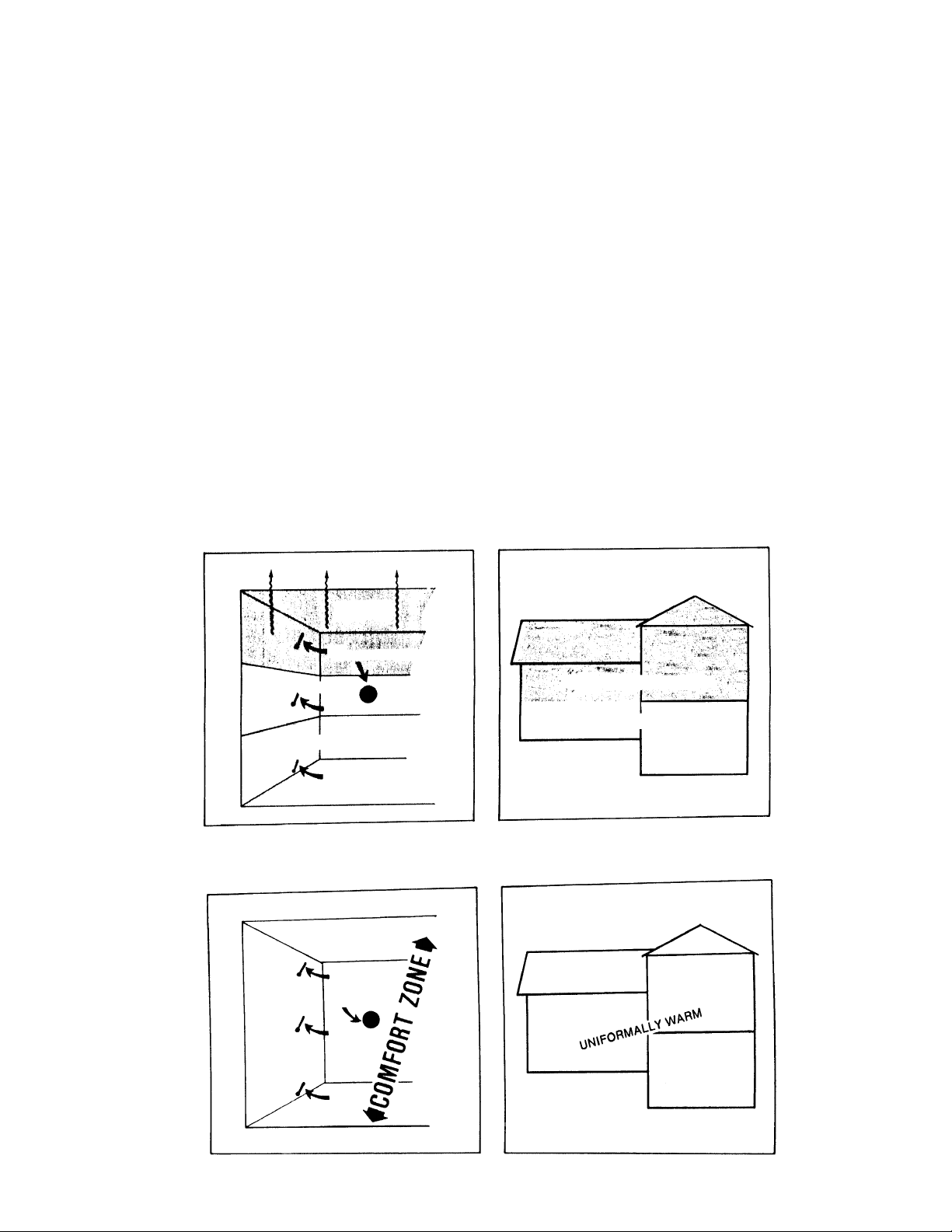
more comfortable and lose less heat through your ceil
ings as illustrated in figure 2.
This situation can be especially troublesome in
multi-level homes as illustrated in figure 3. As soon as
the blower shuts off, the air in the home begins to strat
ify; warm air rising to the upper levels and cool air col
lecting in the lower levels. The lower levels become
increasingly uncomfortable until the blower turns on
again. Unfortunately, the upper levels are still warm so
they become uncomfortably warm before the blower
turns off. By allowing for a steadier, more continuous
operation of the blower the entire house stays at a
more constant and comfortable level, figure 4.
ADDITION COMFORT AND SAVING
-
-
-
But how can all this improve the efficiency of your
home? As figure 1 illustrates, heated air rises away
from the living area and stratifies. This causes large
temperature differentials between the ceiling where
heat is lost rapidly through conduction and the floor
where children often play. By allowing for continuous
air movement, even during periods of low heat output,
this stratification is not allowed to take place. You are
WASTED HEAT
ZONE
82°
THERMOSTAT
COMFORT ZONE
74°
DISCOMFORT ZONE
60°
FIGURE 1
Options are available for your Woodchuck furnace, and
one of these deserve special mention. The Aqua-Si
phon is capable of pre-heating your domestic water
free of charge during the heating season for additional
saving to you.
UNCOMFORTABLY HOT
UNCOMFORTABLY COLD
FIGURE 3
-
75°
THERMOSTAT
74°
73°
FIGURE 2
FIGURE 4
7
Page 8
OPERATION
COMMON SENSE
Please read the following before firing your furnace. It is
most important that you follow these suggestions and
limitations in order to maintain your warranty and guar
antee the long life of your furnace.
NOTE: Smoke detectors and fire extinguishers should
always be a part of your equipment.
This furnace is an airtight unit designed to burn 6-8
hours per load of wood or coal. If the furnace is being
fired hot constantly with full flames and operating at
only 2-4 hour burn cycles, it may be over fired. Your
home heating needs may be too great for the size of
furnace you have purchased. Your furnace can be dam
aged if fired at extremely high temperatures.
Forced firing or abuse can be detected upon inspection
AND WILL VOID YOUR WARRANTY.
DANGER:
RISK OF FIRE OR EXPLOSION. DO NOT BURN GARBAGE, GASOLINE, DRAIN OIL, OR OTHER FLAMMABLE LIQUIDS. FAILURE TO HEED MAY RESULT IN
SERIOUS PERSONAL INJURY OR DEATH.
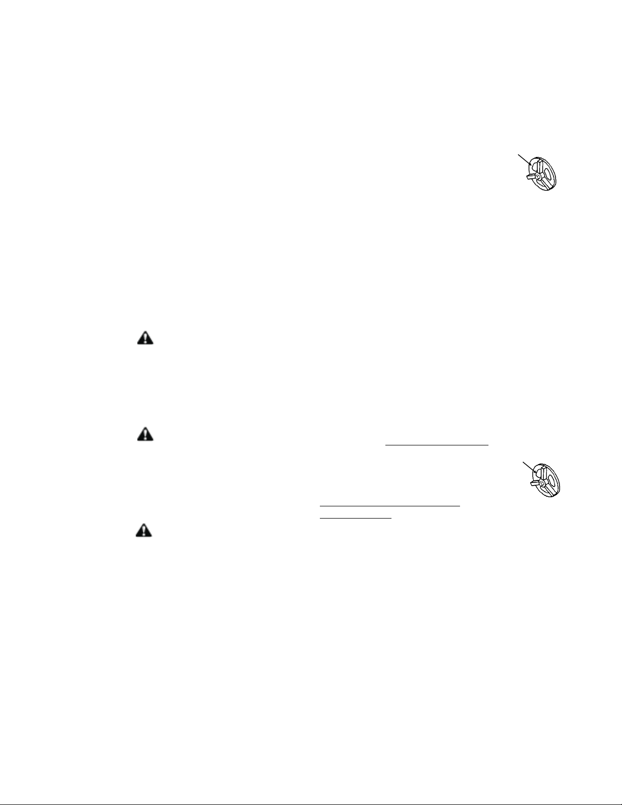
! IF YOU HAVE CHIMNEY FIRE !
Meyer Mfg. Corp. recommends the following actions:
1. Shut any doors and air inlet dampers and draft con
trol. This should take no longer than a few seconds.
CLOSED
2. Alert everyone in the house.
3. Call the fire department.
NOTE: Emptying a large box of baking soda will slow
down the fire in your Woodchuck.
Keeping your chimney and stove pipe clean is the best
insurance against chimney fires.
-
MANUAL DRAFT
! IMPORTANT !
OPERATION PROCEDURE IN THE
EVENT OF POWER FAILURE:
Your Woodchuck can operate and produce heat without
electric power. This is one of the features built into every Woodchuck.
The following steps should be taken in the event of an
electrical power failure:
-
DANGER:
NEVER USE CHEMICALS OR FLUIDS SUCH AS
GASOLINE, CHARCOAL LIGHTER FLUID, DRAIN
OIL, FUEL OIL OR KEROSINE TO LIGHT A FIRE IN
YOUR WOODCHUCK. FAILURE TO HEED MAY RE
SULT IN SERIOUS PERSONAL INJURY OR DEATH.
CAUTION:
·
RISK OF FIRE
·
DO NOT OPERATE WITH FUEL LOADING OR
ASH REMOVAL DOORS OPEN.
·
DO NOT STORE FUEL OR OTHER COMBUSTI
BLE MATERIAL WITHIN MARKED INSTALLATION
CLEARANCES.
·
INSPECT AND CLEAN FLUES AND CHIMNEY
REGULARLY.
·
UNDER CERTAIN CONDITIONS OF USE, CREO
SOTE BUILDUP MAY OCCUR RAPIDLY.
·
WAIT 10 SEC. ON FIRST LATCH BEFORE RE
FUELING.
·
LOAD FUEL CAREFULLY OR DAMAGE MAY RE
SULT.
-
-
-
-
1. Locate all heating duct dampers
damper), if any, to open position.
2. Turn manual draft controls to this position.
Ash door should never be used
in power failure.
3. Remove filter box service access cover, allowing
cooler air to move hot air through the furnace, cooling
the plenum and the house hot air duct system.
If power fails, to avoid product damage, close manual
draft completely. Forced draft and natural draft are pre
set.
In the event of a runaway fire, close all drafts. Close
smoke damper halfway.
(not smoke pipe
CLOSED
MANUAL DRAFT
-
8
Page 9
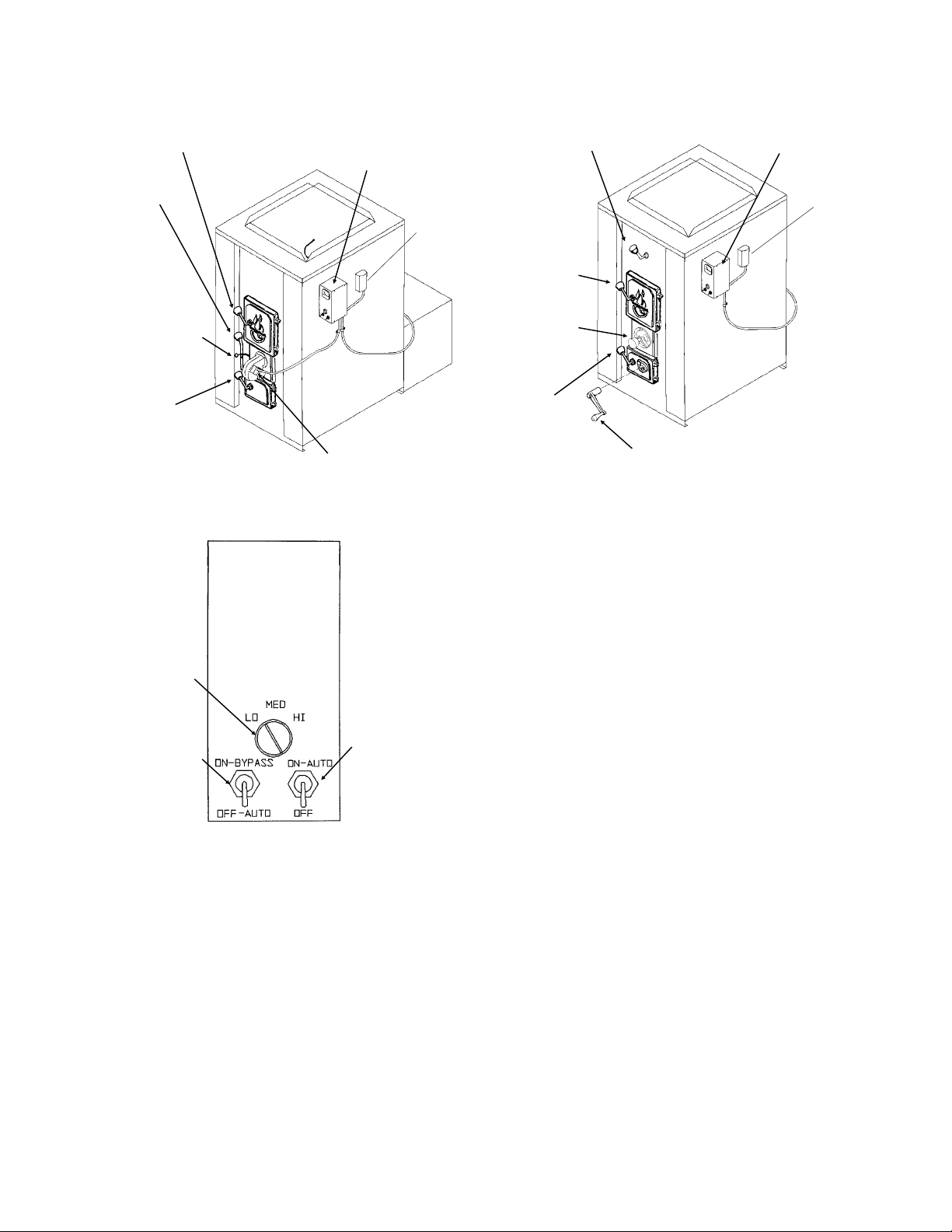
SHAKER
GRATE
DOUBLE LATCH
LOADING DOOR
COMFORT
CONTROL CENTER
FAN/LIMIT
HEAT EXCHANGER
CONTROL ROD
DOUBLE LATCH
LOADING DOOR
COMFORT
CONTROL CENTER
FAN/LIMIT
DRAFT CHANNEL
SELECTOR - 80/20
COMBUSTION AIR
RATIO CONTROL
MODELS
ASH DOOR
2900/4000
FORCED DRAFT
BLOWER
FIGURE 5 WOODCHUCK CONTROLS
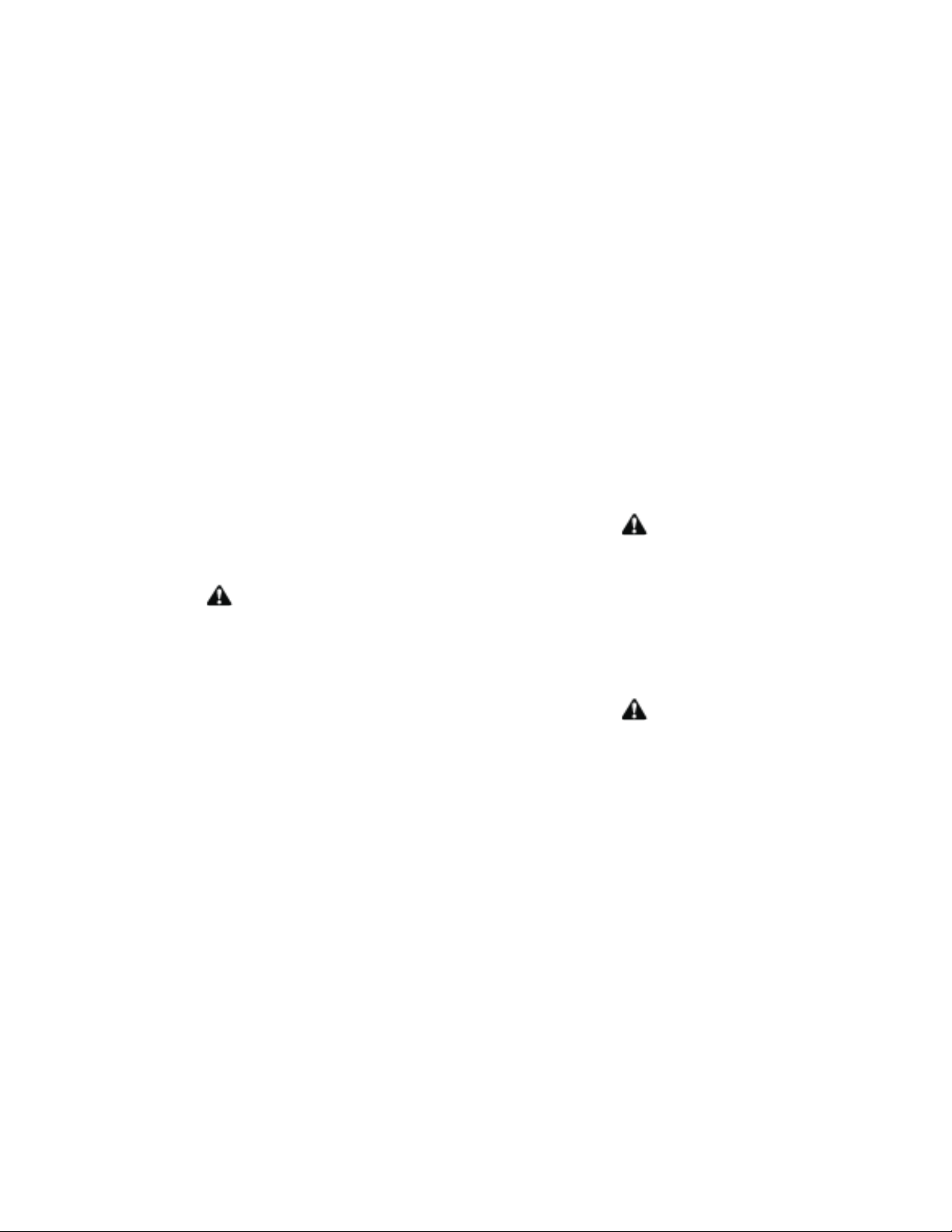
CIRCULATING
BLOWER
DRAFT BLOWER
LO-LIMIT BYPASS
DRAFT BLOWER
MANUAL SWITCH
FIGURE 6 COMFORT CONTROL CENTER
OPERATING YOUR WOODCHUCK
FURNACE
STARTUP
Never leave ash pan in unit. Use only when cleaning
out ashes.
MANUAL DRAFT
(Forced Draft Is
Optional)
ASH DOOR
SHAKER GRATE CRANK.
SHAKER GRATES ARE OPTIONAL
MODEL 526
NOTE: All models are equipped with a “low limit” which
will not allow the auto draft to operate when the unit is
not warm. To start auto draft, turn Lo-Limit toggle switch
on comfort control center to “On”, figure 6.
Now you are ready to light a fire.
BURNING WOOD IN YOUR WOODCHUCK
1. Adjust draft channel selector, figure 5, to appropriate
fuel setting on model 2900/4000. On Model 526 with
manual draft, open it. Place several pieces of crumpled
paper in the center of your Woodchuck. Criss-cross a
couple of handfuls of dry kindling wood 3/4" thickness,
then several small dry pieces of firewood. Ignite the pa
per and close the door. Do not attempt to open the door
immediately after igniting the fire. There could be a
flame flash out.
2. It will take 5-10 minutes for the fire to establish itself.
Once you have some good red hot burning embers,
add larger pieces of wood. All chimneys and hookups
are different. After 3-4 fires, you’ll find out how your unit
works for the best starting.
-
First thing is to check that your main blower and draft
blower are in proper working order before lighting a fire.
To check main blower, push button on fan/limit control
for manual override testing. When finished, reset to au
tomatic position, figure 5. Next, turn thermostat upstairs
to high temperature so draft blower turns on.
3. After about 30-40 minutes you can adjust the draft
according to your needs. Adjust smoke pipe damper ac
cording to your needs also.
-
NOTE: On airtight units, the burning time is controlled
mostly by the draft controls on the furnace, contrary to
9
-
Page 10
the old type of pot belly stoves where the smoke pipe
damper controlled the burning time.
NOTE: With new steel, there is a small amount of oil or
dirt on the metal and you may smell an odor. Provide
adequate ventilating to home during the first operation.
Your new Woodchuck is capable of putting out many
BTU’s, so treat it with respect. Don’t fully load your fur
nace or open all drafts fully until you have become thor
oughly familiar with the operation of the furnace.
NOTE: A full load does not always give the best results
for your needs.
4. When loading your Woodchuck with existing hot
coals, rake red hot embers over grates evenly. Put a
few small pieces of wood on the coals first, then
load-up.
5. If you have the automatic draft control, turn low limit
by-pass switch to “On”. Turn thermostat up to activate
auto draft and proceed as with manual draft. Once the
unit is warmed up you can turn the low limit by-pass
switch to “OFF”. This will allow the auto draft to shut off
if the unit runs out of fuel while you are gone.
CAUTION:
WAIT 10 SECONDS ON FIRST LATCH BEFORE REFUELING. OPENING LOADING DOOR RAPIDLY CAN
CAUSE A FLAME TO FLASH OUT THE DOOR. THIS
OCCURS WHEN THERE IS UNBURNT FUEL AND A
LARGE AMOUNT OF GASES ON TOP OF THE FIREBOX. WHEN THE DOOR IS OPEN, OXYGEN IS COM
BINED WITH GASES AND IGNITES. USE CAUTION
WHEN OPENING LOADING DOOR.
HELPFUL HINTS
Adjust the draft to the proper setting for your home
needs. The chimney, hookups, and kind of wood will
also be a factor.
Your Woodchuck is capable of holding very large logs.
DO NOT try to add a log that is larger than you can
easily place in the furnace. You will get the best effi
ciency when you add only the amount of wood needed
fora6to8hour burn.
mometer at the rear of the furnace on the smoke pipe
where it connects to the collar on the back of the
Woodchuck. 300-400 degrees should be maintained
when the Woodchuck is operating in the burn cycle with
the forced draft blower running to eliminate a creosote
build up. (If the unit has a manual draft or a natural
draft, monitor the flue temperature when the drafts are
in the open position). Depending on the weather, you
may not need a full load of wood for a good over night
burn. You will get best efficiency when you add only the
amount of wood needed until the next time you are
available to load.
Always try to place the logs so air can flow between
them -this will enhance combustion considerably.
ASH REMOVAL
When burning wood, run your poker over top of the
grate to be sure grate slots are clear of burnt fuel. This
should be done every morning when there is just a bed
of hot coals.
CAUTION
NEVER LET ASHES BUILD-UP TO GRATE LEVEL.
THIS WILL GREATLY REDUCE THE LIFE SPAN OF
YOUR GRATE.
Wood ash is useful as a fertilizer, particularly because
of its potassium content. Ashes will also decrease the
acidity of garden soil.
-
·
KEEP ASH PAN OUT OF UNIT DURING OPERA
TION. ASH PAN CAN GET VERY HOT.
·
ASH CAN MUST BE PLACED ON A
NONCOMBUSTIBLE SURFACE.
·
NEVER USE ANYTHING BUT AN AIR TIGHT
METAL CONTAINER TO DUMP YOUR ASHES IN.
EVERY YEAR MANY FIRES ARE CAUSED BY
EMPTYING ASHES INTO CARDBOARD BOXES
OR PAPER BAGS.
·
PROVEN FACT- SMALL RED EMBERS BURIED
IN ASH CANS STAY RED HOT FOR DAYS.
-
ASHES ARE A GOOD THERMAL INSULATOR
AND KEEP ENOUGH OXYGEN AWAY SO THE
EMBERS DO NOT BURN OUT.
CAUTION
-
In the spring and fall, the weather is mild, which will al
low you to burn very large loads of wood for long peri
ods of time and hence accumulate very large amounts
of creosote. KEY: Stack temperature should be
300°F-400°F for good burning. An external flue temper
ature thermometer (Woodchuck part #08-0084) is in
cluded in the owner’s manual package for monitoring
stack temperature. Install the flue temperature ther
-
-
-
-
-
10
Page 11

BURNING COAL IN YOUR WOOD
-
CHUCK
Never attempt to burn coal without a shaker grate.
Shaker grates are standard on Models 2900 and 4000
but optional on Model 526.
A coal fire should not be poked or broken up as this
tends to bring ash to the surface of the coal bed where it
may fuse. If the ash fuses, clinkers will form. It may be
necessary to remove all unburned material and ash from
the firebox to remove clinkers. These should be re
moved with gloves or tongs, and as always, put into a
metallic air-tight container.
-
A barometric draft control in the smoke pipe must be
used when burning coal.
CAUTION:
UNSAFE TO LOAD COAL ABOVE TOP OF FIRE BRICK.
STARTING A COAL FIRE
Open all draft controls on your Woodchuck.
Build a fire using dry wood kindling and establish a bed
of coals. Add several small shovels of coal over the
wood coals. After the coal fire is established and spread
throughout the firebox, add larger amounts of coal to
build up the coal bed. Gently shake the grate until live
coals fall into the ash pan area. Allow your Woodchuck
to operate with drafts open for approximately 15 minutes
or until fresh coal ignites. When the coal is properly ignited, adjust the drafts accordingly. Check the fire periodically to be sure it is spreading through the coal bed.
RECHARGING
Gently shake grates down. Open drafts and establish a
good flow of primary air below the grates. When recharging, fresh coal tends to give off large quantities of
volatile gas. This gas may accumulate and possibly ig
nite causing a backpuff. To reduce back-puffing, open
the fire door to the first safety latch position for 15-20
seconds before opening fully. Spread fresh coal evenly
over existing coal, leaving some hot coals exposed in
the center of the firebox. Be careful not to smother your
existing coals. Never allow coal to build up above the
top of the firebrick. When blue flame creeps up between
the coals, drafts may be adjusted to maintain burn level.
If the coal fire dies down before recharging, a fresh sup
ply of kindling may have to be added.
BANKING
Banking allows you to recharge in such a manner as to
retain a hot coal bed throughout the night. Approxi
mately an hour before retiring for the night, push the
coals to the rear of the firebox with the coal tapered
down in the front. Add a new layer of coal. Always leave
some hot coals exposed in the front. This allows for
more coal to be added to the firebox.
BITUMINOUS RECHARGING
Because bituminous coal has a higher percent of sul
phur and lower percent of fixed carbon than anthracite,
recharging should be as follows:
Gently shake down grates, with drafts open and a good
flow of primary air entering below the grates. Push the
hot coals to the rear of the fire box and position fresh
coal on the grate in front of the banked coal. As the
fresh coal begins to burn, wood may be added to the top
of the coal.
NOTE: Woodchuck recommends coal 1 inch to 3 inches
in diameter. Ashes may be sifted through a mesh screen
to reclaim particles of unburned coal.
HELPFUL HINTS
Burning coal will provide a lesson in patience. Take the
time necessary to experiment and understand the operation of your Woodchuck wood/coal furnace.
Too much draft air will cause clinkering of coal and will
waste heat up the chimney. Shut draft down to as low a
point as you can and still heat your home.
-
1. NEVER stand in front of loading door when opening
it. Stand to the side.
2. NEVER completely cover the live fire with fresh coal.
Always leave a generous area of burning coal at the top
of the fire and at the rear.
3. Always keep the ash pit clean.
If the fire goes out or does not hold overnight look for:
-
1. Poor draft.
2. Incorrect damper settings.
3. Improper firing methods for coal being used.
4. More combustion air needed.
5. Coal not sized to furnace. We recommend 1" to 3" di
ameter pieces of coal.
-
6. Ashes, if allowed to accumulate in the ash pit, will not
allow the required air for combustion. Keep ash pit
clean.
-
-
11
Page 12

ASH REMOVAL
Ash should always be put into an air-tight, metal con
tainer.
CAUTION
KEEP ASH PAN OUT OF UNIT DURING OPERA
·
TION. ASH PAN CAN GET VERY HOT.
ASH PAN MUST BE PLACED ON A
·
NONCOMBUSTIBLE SURFACE.
NEVER USE ANYTHING BUT AN AIR TIGHT
·
METAL CONTAINER TO DUMP YOUR ASHES IN.
EVERY YEAR MANY FIRES ARE CAUSED BY
EMPTYING ASHES INTO CARDBOARD BOXES
OR PAPER BAGS.
PROVEN FACT- SMALL RED EMBERS BURIED
·
IN ASH CANS STAY RED HOT FOR DAYS.
ASHES ARE A GOOD THERMAL INSULATOR
AND KEEP ENOUGH OXYGEN AWAY SO THE
EMBERS DO NOT BURN OUT.
MAINTENANCE
Coal firing produces much more ash than wood. These
ashes must be removed often (possibly daily) in order
to avoid piling up too closely to the grates. Removal of
the coal ash will prevent warpage and damage to
grates, and allow passage of primary air to the coal
bed.
Unlike wood ash, coal ash cannot be used as fertilizer.
All coal contains small amounts of dangerous elements.
It is therefore essential that your coal ash be disposed
of in municipally designated areas.
WARNING:
DISCONNECT APPLIANCE FROM ELECTRICAL
SUPPLY BEFORE SERVICING UNIT. FAILURE TO
HEED MAY RESULT IN SERIOUS PERSONAL INJURY
OR DEATH.
Keep chimney and smoke pipe clean by cleaning at least
twice during a heating season. Keeping your chimney
and stove pipes clean is the best insurance against
chimney fires.
If you clean your own chimney and stovepipe, Meyer
Manufacturing Corp. recommends purchasing the same
equipment professionals use. Brushes are available in
enough sizes and shapes to snuggly fit inside any com
mon flue.
Replace any cracked or deteriorated firebrick. This will
prolong the life expectancy of the firebox.
Check door gasket and replace as needed.
Oil blowers every 6 months of use. (SAE 10 motor oil re
quired.)
OPTIONAL CATALYTIC COMBUSTOR
FOR MODELS 2900/4000
NOTE: Optional catalyst not recommended for Model
2900/4000 with 6" flue adapter. Smoke spillage may occur out of door when refueling.
Even with complete combustion there is a small amount
of residue. Eventually enough will collect on the
combustor to interfere with its operation. Therefore it is
necessary to clean it periodically. To clean the
combustor simply remove from unit and run tap water
through it until no sign of residue remains. The
combustor simply slides up into the exhaust pipe stub
which protrudes down into the firebox. There are three
rods on the combustor which engage slots in the pipe
and then turn slightly to lock in place. These rods are not
symmetrical so observe their orientation when you re
move it. Two rods are welded at 90° and they point to
ward the rear of the firebox.
NOTCHES IN EXHAUST
PIPE
-
-
-
Keep ash pit clean especially when burning coal.
Turn on your regular furnace once every month to keep
it tuned up and limber.
CATALYTIC ELEMENT
RODS ON RETAINER
OPTIONAL CATALYTIC
COMBUSTOR
12
Page 13

TROUBLE SHOOTING
PROBLEM POSSIBLE CAUSE SOLUTION
1. Main blower vibrating
when in use.
2. Main blower continues to
run.
3. Main blower won’t turn
on.
4. Draft blower staying on. Wall thermostat bad, check by turning temp. to
5. Draft blower not turning
on. NOTE: Be sure switch
on blower is on.
6. Smell an odor from the
first fire in the furnace.
7. Not getting heat in the
home.
8. Flames coming out the
door when loading.
Loose Allen screw on squirrel cage.
Bad motor bearings.
Weights on squirrel cage wheel moved in ship
ment.
Manual control turned on (fan/limit control). Check fan/limit control switch. Push
Defective fan/limit control.
Defective 3-speed blower switch.
Defective circulation blower motor.
60° then check if draft blower is running.
Short in thermostat wire.
Home not getting heat needed to satisfy wall
thermostat.
Switch blower to the off position. Bad wall Thermostat; check by turning it up to 80° and if the
draft blower does not turn on, replace thermostat.
Lo limit bypass on “off”.
New steel, small amounts of residue on the
steel.
Bad weld, if smell continues for two weeks of
burning.
Unit may be too small for your home; check
specification chart.
Improper insulation in home allowing heat to
escape.
Improper hookup to furnace.
Ducting not sized properly for unit.
Excessive amount of gases on top of the fire
box and igniting when given oxygen from open
door. NOTE: This is one of your Woodchuck
safety features built into every unit with a dou
ble latch system.
Large amounts of unburned wood. Try to load when fire is at its lowest
Tighten Allen screw, be sure squirrel
cage did not move to one side or the
other.
Return blower to your local dealer
for a replacement.
Try to adjust it yourself or return
blower for replacement.
for manual, pull for auto. If in auto
position, replace fan/limit control.
Replace.
Replace.
Replace.
Replace wall thermostat.
Check all wiring again.
Check on spec’s chart to be sure
your unit is large enough for your
home. Be sure installation is proper:
check with your local heating man.
Replace thermostat.
When starting up it is necessary to
turn toggle switch on front of comfort
control center to “on” until unit
warms up.
This will disappear in a matter of
hours.
Contact dealer immediately.
Replace with a larger unit or have
regular furnace help.
Reinsulate!
Check installation drawings and/or
consult your local heating man.
-
point, but have enough embers left
for a good start again. NOTE: Only
you will know this time after some
experience with your unit and instal
lation.
-
13
Page 14

PROBLEM POSSIBLE CAUSE SOLUTION
9. Excessive amounts of
smoke coming out loading
door when loading.
10. Puffing of smoke
through draft control.
Improper draft.
Chimney cap too close to top of chimney.
Too long of run of smoke pipe from Woodchuck
to chimney.
Improper draft.
Down draft on chimney.
Measure with draft gauge-should
have .04 to .06 water column.
Relocate.
Relocate Woodchuck closer to
chimney.
Check draft with gauge. Should be
.04 to .06 water column.
Check for cold spots on chimney
or obstruction outside chimney.
Trees or other buildings.
Plugged chimney.
Check with mirror in clean-out
door or send cleaning brush down
chimney. Check stovepipe con
nections.
11. Excessive dirt build-up
around air vent in home.
12. Improper seal around
door.
Too much smoke escaping out of loading door
when loading.
Bad weld in fire box of unit.
No return air ducting.
Door rope not sealing on door frame.
Check problem No. 9.
Call dealer immediately.
Install return air duct.
Check door rope so that all parts
of door frame are sealed, espe
cially corners.
Loose door from shipment.
Simply bend door latch in to
tighten door seal.
13. Excessive creosote
build-up.
A reminder, whatever kind of
fuel you burn, there is some
kind of residue build-up on
the furnace and chimney.
Same with wood no matter
how good the conditions.
The use of wet, frozen, or unseasoned wood.
The use of soft wood, particularly those of high resin
content such as plywood or blandex with glue.
Poor natural draft or an obstruction in the stove
pipe or chimney flue.
Too long of burning times.
Inadequate amount of oxygen supplied to the
combustion chamber
If you have to use wet wood, make
loads smaller and burn them hotter.
Avoid using if possible.
Measure draft with gauge. Should
have a minimum of .04-.06 water
columns of draft.
Smaller and hotter fires.
Adjust draft for hotter fires or in
some homes, it has been determined there was not enough in the
basement due to such an air-tight
home. We recommend 4" round
hole to the outside with a screen
on to keep varmints out.
Low fire or flue gas temperatures.
Smaller loads of wood and hotter
fire. Stack temps. should maintain
minimum 300° to 400°.
Uninsulated stovepipe or chimney flues, espe
cially if construction is exterior to the house.
-
Never use uninsulated pipe for
chimneys installed on the outside
of the house, INSULATE!
Air leaks in the stove pipe or chimney.
Check chimney from top to bot
tom. NOTE: Creosote is a tarry liq
uid or solid coming from distillation
of wood during the combustion
process. The heavier buildups, the
greater chance of a chimney fire.
NOTE: No matter how seasoned
the wood, no matter how good the
draft, you always will get a small
amount of soot buildup. Should be
cleaned before winter firing and
during mid-winter’s firing.
-
-
-
-
14
Page 15

INSTALLATION
GENERAL REQUIREMENTS
CAUTION:
EQUIPMENT MUST BE INSTALLED BY A QUALIFIED
HEATING PERSON.
CAUTION:
ONLY “CLASS A” ALL-FUEL OR SOLID FUEL CHIM
NEYS INTENDED FOR USE WITH YOUR WOOD
CHUCK SHOULD BE USED.
FIRST AND ABOVE ALL is safety for you and your
family.
-
-
MUST USE: Class A Masonry or ULC listed, manufac
tured Class A All Fuels Chimney.
RECOMMENDED SIZE: Rectangular 8"x12" or Round
8".
DO NOT CONNECT THIS UNIT TO A CHIMNEY FLUE
SERVING ANOTHER APPLIANCE. The Woodchuck is
to be used in conjunction with a listed gas or oil fired
furnace or as a central furnace.
ELECTRICAL SUPPLY: 115 volts, 60HZ, 1 Phase,
less than 12 amps.
Install system with 0.2 static pressure.
Flue setting .06 W.C. Max to .04 W.C. Min.
Wood or coal related fires are caused almost exclu
sively by installation, operation or maintenance errors;
but not by unsafe equipment.
IMPORTANT: Check with your local state and federal
codes on installation at your local fire department.
PLACEMENT AND MINIMUM CLEAR
ANCES
-
-
-
CAUTION:
FURNACE MUST BE INSTALLED ON A NON-COM
BUSTIBLE FLOOR OR 3/8" THICK FIREPROOF MILL
BOARD OR EQUIVALENT.
Locating your unit is very important for proper draft and
most efficient heating possible. See figure 7.
-
-
FIGURE 7 LOCATING THE WOODCHUCK
15
Page 16

THE CAP SHOULD BE SUCH THAT IT HELPS TO PREVENT
DOWNDRAFT WHILE PROVIDING ADEQUATE EXHAUST
DRAFT.
TOP OF CHIMNEY MUST BE AT LEAST 2’ HIGHER THAN PEAK
OR HIGHEST PORTION OF ROOF WITHIN 10’ HORIZONTALLY.
ALSO SEE FIGURE 9.
A CHIMNEY WHICH RISES WITHIN HOUSE IS BETTER
INSULATED THAN A CHIMNEY WHICH IS LOCATED OUTSIDE
THE HOUSE AND IS EXPOSED TO WEATHER.
THE CHIMNEY FLUE MUST HAVE A CROSS SECTIONAL AREA
AT LEAST EQUAL TO OR LARGER THAN THAT OF THE
STOVES FLUE COLLAR; BUT NO MORE THAN TWICE THAT
AREA.
MIN. 3’ FROM TOP OF CHIMNEY TO POINT AT
WHICH IT PASSES THROUGH THE ROOF
RECOMMENDED MIN. HEIGHT
APPROX. 20’
THE CHIMNEY THIMBLE SHOULD BE CONSTRUCTED OF
FIRE CLAY AND SHOULD HAVE AN INSIDE DIAMETER WHICH
IS NOMINALLY EQUAL TO THE OUTSIDE DIAMETER OF THE
SMOKE PIPE TO ASSURE A REASONABLY AIR TIGHT FIT.
THE THIMBLE MUST NOT EXCEED BEYOND THE FLUE
LINING.
FLUE SHOULD BE OF CONSTANT CROSS
SECTIONAL AREA THROUGHOUT ITS LENGTH
CLEANOUT DOOR SHOULD BE PROVIDED AND IT MUST
HAVE AN AIRTIGHT FIT. IT SHOULD NOT BE LEFT OPEN
FOR ANY LENGTH OF TIME WHEN STOVE IS IN
OPERATION
FIGURE 8 TYPICAL CHIMNEY CHECKLIST
16
Page 17

Your unit should be place on a non-combustible floor or
3/8" thick fireproof millboard or equivalent which ex
tends at least 8" from the sides and rear and extends
24" from the front. Leave a minimum clearance of 36" in
front of your unit. This is for safe, easy loading and
cleaning of your unit.
Also be sure to allow enough room at the rear of the
Woodchuck for installation of the circulating blower and
filter box.
which can ignite and cause severe damage to any
chimney. MAKE SURE YOUR WOODCHUCK IS IN
STALLED INTO A PROPER CHIMNEY.
For maximum safety and efficiency never install the
Woodchuck furnace into the same chimney serving an
other appliance.
A typical chimney checklist of requirements is depicted
on figure 8.
-
-
If using your unit as an add-on, 6" minimum clearance
is required from your present furnace.
One very important step in locating your wood/coal fur
nace is how much distance you will be from your new or
existing chimney. The unit should be installed as close
to the chimney as possible with a minimum of elbows
(no more than 2) and no more than 6 feet horizontally
with ½" rise per foot.
CHIMNEY INSTALLATION
It is extremely important that your Woodchuck furnace
be installed into a CLASS A CHIMNEY ONLY. These
chimneys consist of a flue-lined masonry chimney or
an approved Class A All Fuel factory built metal type.
Any other installation constitutes a fire hazard, as wood
and coal burning units have stack temperatures as
much as 300° to 1000° and may also deposit creosote
10’ MIN.
2’ MIN.
The Model 526 furnace is equipped with a 6" flue collar
having 28 sq. in. of exhaust area. Models 2900 and 4000
have an 8" flue collar having 50 sq. in. of exhaust area.
When connecting the furnace to the chimney maintain a
chimney flue section giving these minimum areas or
larger but not exceeding twice this area. Some common
sizes that are acceptable are 8" round, 10" round, or
8"x12" rectangular. All Woodchuck furnaces must be in
stalled into a chimney developing a minimum of .04 W.C.
to a maximum of .06 W.C. inches of draft. To maintain
this range of draft, a barometric damper should be in
stalled (see pgs. 18-20) on each unit when the draft from
the chimney is capable of exceeding .06 W.C. inches of
draft.
Insufficient draft can contribute to smoke spillage when
the loading door is opened and to rapid creosote accumulation. Excessive draft can cause high flue gas temperature, loss of overall efficiency and effect the degree
of control the operator can exert on the unit.
3’ MIN.
2’ MIN.
-
-
APPROVED CHIMNEY
6" OR 7" PIPE FOR
MODEL 526
8" PIPE FOR
MODELS
2900/4000
SIDE VIEW
APPROVED
CHIMNEY
STOVE PIPE
DAMPER
DAMPER
FRONT VIEW
FIGURE 9 CHIMNEY/ROOF CLEARANCE
TYPICAL STOVE PIPE INSTALLATION
17
Page 18

When using approved factory built metal chimneys, you
must have at least 2" of clearance when going through
a wall or next to a wall. A typical factory chimney instal
lation is shown on figure 9.
INSTALLING YOUR WOODCHUCK
Most of the Woodchuck furnace is factory assembled.
The factory assembly should be located as detailed in
the PLACEMENT AND MINIMUM CLEARANCES sec
tion and on figure 7.
Remaining assembly will consist of mounting the con
trols, draft and circulating blowers, filter box if used, and
electrical connection. These details will be provided af
ter stove pipe and air duct installation.
STOVE PIPE INSTALLATION
Install your Wood/Coal unit as close to the chimney as
possible with a minimum of elbows. We recommend no
more than two elbows. The maximum horizontal run
should not exceed 6 feet with a ½" rise per foot. The
pipe should maintain a ½" rise per foot and NEVER be
installed closer than 18" from combustibles. Exceeding
these recommendations normally represents creosote
build-up, a smoking furnace, or one with poor draft.
When connecting stove pipe, all joints should be secured with at least three #10 sheet metal screws.
NOTE: If it is absolutely necessary to make a run
greater than 6 feet (not recommended), use extra support brackets every 3 ft.
The connection to the wood furnace’s collar must also
be more than just a snug fit. Drill holes through the
Woodchuck’s collar and secure with sheet metal
screws. Mark each connection for cleaning. This will
prevent frustration when matching up your hole pattern
again.
DAMPERS IN STOVE PIPES:
A manual damper may be installed at a safe convenient
place between the barometric damper and the chimney.
In the event of chimney fire, it can quickly be closed
reducing draft to the chimney. See figure 10.
SUGGESTED TYPE
DAMPER
INSTALLATION OF A BAROMETRIC DRAFT
Some codes and NFPA require draft regulators in the
chimney connector of wood or coal furnaces and boil
ers, and manufacturers recommend their use with some
stoves. There is some doubt among wood heat experts
as to whether use of barometric draft regulators is wise.
Draft regulators limit the draft-the suction pulling air into
the appliance. A pivoted, counter-balanced flap is
pulled open by the draft when the draft reaches a criti
cal amount (figure 10). This permits air to enter the
chimney, thus preventing the draft in the appliance from
rising any higher.
Use of draft regulators with oil-fired equipment is com
mon. One objective is to keep the oil flame from being
blown out by excessive draft. This is more an annoy
ance than a safety problem since most oil burners have
primary safety controls which stop the fuel flow into the
burner whenever the flame goes out, and modern
flame-retention burner design makes draft regulation al
most unnecessary for this objective.
A second objective is to limit the amount of air passing
through the system in order to maintain high heat transfer efficiency. Another desirable consequence is a decrease in peak chimney temperatures due to the added
air entering through the regulator.
High draft does not blow out the flames but fans them in
wood and coal burning equipment. An especially hot
fire can result. Control of the fire may be difficult, particularly if the wood burner is not airtight. Energy efficiencies may be adversely affected, and chimney fires may
be ignited. A barometric draft regulator can alleviate
these problems by limiting the flow of combustion air
into the appliance and by adding cooling air to the hot
flue gases.
However the cooling air may result in more creosote
accumulation, and if a chimney fire does start, it will be
more intense because of the draft regulator. Large
flows of air into the regulator will fan the fire in the
chimney. Thus the net effect of barometric draft
regulators is unclear-they help in some aspects, and
hurt in others. Note, though, that if a chimney is clean
so that chimney fires are impossible, a draft regulator
does no harm, and does help limit the intensity of the
fire in the appliance, and it helps prevent the flue gases
in the chimney from getting too hot. Barometric draft
regulators are recommended by JFPA for hand fired
thermostatically controlled solid fuel furnaces.
-
-
-
-
-
AIR HOLES
18
Page 19

MANUAL DAMPER MAY BE
INSTALLED BETWEEN BAROMETRIC
DAMPER AND CHIMNEY
With no draft in chimney, regulator
is closed, no air gets in.
Moderate suction in chimney pulls regulator open
enough to maintain desired draft for appliance.
FIGURE 10 A BAROMETRIC DRAFT REGULA
TOR AND ITS INTENDED EFFECT
AIR DUCT INSTALLATION
SPECIAL AIR FLOW CONSIDERATIONS FOR
WOOD/COAL FURNACES
With Wood/Coal furnaces, a special concern is preventing wood joists and flooring close to the hot air
ducts and plenum from overheating. A fire hazard is
created by the hot air flow circulating through ducts not
designed for such high temperatures. Most Wood/Coal
furnaces produce much hotter air than oil or gas fired
units. So most clearances from the existing ducts and
plenum are usually inadequate with a supplemental
Wood/Coal furnace installation.
When installing the air duct, follow recommended
clearances shown in figure 11.
The plenum on the Woodchuck should be 20"x23" and
no less than 18" high while maintaining a minimum of
18" clearance to the ceiling or other combustible mate
rial. In a power outage situation, excessive heat
buildup at the plenum top may be dangerous, so make
sure clearances are maintained. For the Model 4000
allow at least 4" from ceiling to plenum.
-
Excessive suction in chimney pulls regulator further
open, allowing substantial air into chimney connector.
of 600 ft/min to 1000 ft/min at the registers. NEVER
supply less than 150 sq. in. of heated air outlet area.
Cold air returns must be at least equal in size to the
heated air outlets and preferably 10% larger. Every
Woodchuck furnace MUST be installed with a cold air return.
ADD-ON INSTALLATIONS
Before installing your Woodchuck furnace, consult
your furnace man and local state building codes to de
termine if your furnace will accept an add-on applica
tion. Some small furnaces and especially counter-flow
furnaces may not be used in add-on installations.
Once it has been determined that your existing fur
nace will accept an add-on installation, we recommend
a parallel installation, with direct (ducted) feed of re
turn air to the Wood/Coal furnace, see figure 12. The
back flow prevent damper assures that when either
unit is operating by itself, the hot air will flow into the
home, and not flow back through the other furnace.
Figure 13 shows a central installation.
-
-
-
-
The ducts, fittings, grilles and registers should be
sized so that the total external static pressure does not
exceed .02 W.C. inches while developing air velocities
We do not recommend supplemental wood furnace
installations with series connection. These types of
installation are not advisable in spite of their simplicity,
see figure 14.
19
Page 20

FIGURE 11 HOT AIR DUCT CLEARANCE REQUIREMENTS
FIGURE 12 PARALLEL ADD-ON INSTALLATION
WOODCHUCK FINAL ASSEMBLY
OPTIONAL SHAKER GRATE INSTALLATION
FOR MODEL 526
1. Remove standard grates from firebox. Assemble com
plete shaker grate kit outside of unit. Figure 16.
FIGURE 13 CENTRAL ADD-ON INSTALLATION
2. Assemble the left front bar (different from right front bar,
has shorter extension shaft at front) to a rear bar. Slide a
gear onto the front shaft.
3. Set this assembly into the front frame first and then into
-
the rear frame.
20
Page 21

4. Assemble the right front bar to a rear bar. Slide a gear
onto the front shaft, aligning it to engage the gear on the
left bar. Place the front bar onto the front frame and then
setting the rear bar onto the rear frame.
5. Place rear retainer in place, then the center and the
front retainers. Place all four bolts through retainers and
frame. Secure with locknuts. To prevent binding, it is ad
visable to snug the locknuts but do not over tighten.
6. Try moving the shaker grate bars with the handle.
NOTE: Both bars in normal position should be flat. If not,
one or the other gear is not aligned correctly.
7. To install the assembly into the unit, place the front
end of the assembled grate on the loading door lower
frame. The grate should be the upside down position.
Slide the grate (front end first) into the firebox allowing
the front end to lower into the hearth area. Once the
back end of the grate has cleared the door frame, “flip” it
over toward the rear of the unit. If necessary, reach into
the ash pit door and pull the front of the grate forward
until it lodges into place.
INSTALL SHAKER GRATE HANDLE,
MODEL 2900 ONLY
-
1. Open the door ash door. Slide the shaker grate handle
through the opening in the side of the door frame and
guide it through the actuator arm and into the receiving
boss on the opposite side of the frame.
2. Secure handle to actuator with 1/4x1-1/2 bolt and nut.
See figure 15.
SHAKER GRATE HANDLE
ACTUATOR ARM
RECEIVING BOSS
1/4x1-1/2 BOLT
FIGURE 14 POOR INSTALLATIONS
ALIGN HOLES
ASH DOOR FRAME
FIGURE 15 INSTALL SHAKER GRATE HANDLE
21
Page 22

REAR BAR
RETAINER
CENTER
RETAINER
RETAINER
LEFT FRONT BAR
RIGHT FRONT BAR
(NOTE LONG SHAFT ON
FRONT)
HANDLEREAR FRAME
GEARSLOCKNUTS
FRONT FRAME
FIGURE 16 INSTALL OPTIONAL SHAKER GRATE FOR MODEL 526
INSTALL FIREBRICK
Place firebrick into unit as follows:
1. Place two longer bricks with bevel cuts against the
rear wall of the firebox. See figure 17.
2. Place remaining two bricks with bevel cuts against
the front wall of firebox.
3. Place rectangular brick along side walls of firebrick as
illustrated. If Rectangular bricks are two different widths,
then an equal number of each will go on both sides of
firebox.
INSTALL OPTIONAL CATALYTIC
COMBUSTOR (MODEL 2900/4000)
NOTE: Optional catalyst not recommended with 6" flue
adapter. Smoke spillage may occur out of door when
refueling.
RECTANGULAR
BRICKS ON
SIDES
RECTANGULAR
BRICKS ON SIDES
BEVEL CUT BRICKS
FRONT & BACK
MODELS 2900/4000
BEVEL CUT BRICKS
FRONT & BACK
Greater efficiency can be obtained when burning wood
by use of a catalytic combustor. In addition, it will de
crease the accumulation of creosote and diminish the
possibility of a chimney fire.
-
MODEL 526
FIGURE 17 INSTALL FIREBRICK
22
Page 23

The pyrolysis of wood produces certain substances
which will not burn unless the temperature in the firebox
reaches 1000°F or higher. Under normal conditions
these temperatures are not attained and these sub
stances simply escape up the chimney as wasted energy
and can form deposits in the chimney. By forcing these
unburned substances to come into contact with a cata
lyst, we can cause them to burn at much lower tempera
tures that are easily attainable during normal operation.
Installation and removal of the combustor is simple, the
element fits inside a retainer. The retainer fits inside the
furnace exhaust pipe which extends down into the fire
box. The assembled combustor slides up into the ex
haust pipe stub which protrudes down into the firebox.
There are three rods on the retainer which engage slots
in the pipe and then turn slightly to lock in place. These
rods are not symmetrical. Two rods are welded together
to form a 90° angle. This angle points toward the rear of
the firebox.
-
1/4 LOCKNUT
-
-
DO NOT REMOVE
KNOCKOUT
MANUAL DRAFT
CONTROL
-
-
1/4x1-1/2 BOLT
FIGURE 19 INSTALL MANUAL DRAFT-MODEL 526
SLOTS IN EXHAUST PIPE
CATALYTIC ELEMENT
RODS ON RETAINER
FIGURE 18 INSTALL OPTIONAL CATALYTIC
COMBUSTOR (MODEL 2900/4000)
ASSEMBLE MANUAL DRAFT
MODEL 526 ONLY
Using a 1/4x1-1/2 bolt and locknut, mount manual draft
control onto the draft channel, figure 19. If you are going
to install optional forced draft, disregard. Do not tighten
too tight to damper draft adjustment, but not too loose to
let more air in than required. DO NOT remove knockout
on draft channel. Locknut can be held with wrench in
serted through air opening.
INSTALL COMFORT CONTROL CENTER
AND FORCED DRAFT BLOWER
1. Install all knobs to control levers and door handles.
See figure 20.
2. The comfort control center is factory wired to the
fan/limit control and the forced draft blower. It has a
prewired flexible conduit for connection to the circulating
blower.
3. If you have optional temperature gauge on your con
trol, then strip ½" of insulation from the two leads of ther
mocouple wire protruding through the rectangular
opening on the furnace side. Connect these leads to the
terminals on the temperature gauge of the control. IM
PORTANT: Remove the wire ground clip from the termi
nals of the gauge and connect White wire to + terminal
and Red wire to - terminal. See figure 22.
4. Mount the control to the side of the furnace with four
#10 sheet metal screws.
5. Remove the knockout section of the draft channel on
model 526 by striking sharply with a hammer. Be careful
so you do not damage the mechanism inside the chan
nel and directly behind the knock-out. DO NOT allow the
knock-out to fall inside the draft channel.
6. Align the forced draft blower outlet flange over the
knockout and secure with three #10 sheet metal screws.
-
7. Secure conduit to furnace side using conduit clamps
and #10 sheet metal screws.
-
-
-
-
-
23
Page 24

INSTALL ALL CONTROL
AND HANDLE KNOBS
KNOCKOUT IN DRAFT
CHANNEL REMOVED
FORCED DRAFT
BLOWER
THERMOCOUPLE WIRE
COMFORT CONTROL CENTER
FAN/LIMIT CONTROL
SECURE CONDUIT WITH
CONDUIT CLAMPS AND
#10 SHEET METAL SCREW
PRE-WIRED FLEXIBLE CONDUIT
TO CIRCULATING BLOWER
FIGURE 20 INSTALL COMFORT CONTROL
CENTER AND FORCED DRAFT BLOWER
INSTALL CIRCULATING BLOWER
The flanges on the circulating blower simply slide be
hind the angle mounts welded to the rear of the furnace.
Slide in from the top side, figure 21.
INSTALL FILTER BOX
The filter box is standard on Model 526. Installation in
structions are included with Model 526 filter box.
1. The filter box can be installed with the filter on either
side. The access door will fit the opening either side and
the handle should face forward.
2. Find two factory shipped support angles. Force sup
port angle sides without tabs into the groove of the
mounting strip on both rear sides of the furnace. Posi
tion at correct height to accept filter box, figure 21.
3. With filter box set against back of furnace, bend
down the tabs on the support angles so they lock be
hind the flanges of the top and bottom panels of the
box.
4. Install the access door. Install filter not supplied
and install a cold air return system to the filter box fil
ter side opening.
-
5. Route flexible conduit from comfort control through
hole in top panel and to box connector on blower
connection box. Connect wires to blower motor by
joining wires of the same color.
FEED MOTOR
-
White White/Purple
Red Red
-
Blue Blue
Black Black
-
-
24
Page 25

SLIDE FLANGES OF
CIRCULATING BLOWER
BEHIND ANGLES ON BACK
OF FURNACE
FILTER (NOT
SUPPLIED)
ACCESS DOOR
ELECTRICAL
CONNECTION BOX
FORCE FLANGE OF SUPPORT
ANGLE INTO GROOVE ON FURNACE
MOUNTING STRIP
HOLE FOR
CONDUIT
FILTER
ANGLES
GROOVE IN
FURNACE
MOUNTING STRIP,
BOTH SIDES
SUPPORT ANGLE
BEND TABS ON SUPPORT ANGLE
OVER, BEHIND FLANGE ON FILTER
BOX, TOP & BOTTOM
FIGURE 21 INSTALL CIRCULATING BLOWER AND FILTER
ELECTRICAL HOOKUP (FIGURE 22)
former in the comfort control. These connections have
been routed to a terminal strip on the outside of the
1. If you have an optional temperature gauge to monitor
comfort control box for convenient connection.
heat exchanger temperature in your comfort control
center, then the thermocouple wires must be connected
to the gauge when installing the control. See figure 20.
IMPORTANT: Remove the wire ground clip from the ter
minals of the gauge and connect White wire to + termi
nal and Red wire to - terminal. See figure 22.
4. The circulating blower limit control is factory wired to
the comfort control center. Jumper removed, normal fan
limit control settings are 160°F ON, and 110°F OFF.
-
-
5. Route 110VAC power through conduit from your
power supply to the comfort control center box. Route
through box connector provided and connect hot (L
2. A prewired conduit is connected to the comfort con
trol center for the circulating blower. The opposite end is
to be connected in the junction box on the blower motor.
Connect like colored wires. Secure conduit to junction
box with box connector.
BLACK, Neutral to WHITE and ground to GREEN as
shown on figure 22. You must provide a power discon
nect in the power supply line to your furnace which is
within sight of the Woodchuck and not more than 30
feet away. Your circuit breaker at the power supply may
3. The comfort control is factory wired to the forced draft
meet these requirements.
motor (optional on Model 526). If you have the forced
draft, locate a wall thermostat in the desired location of
you house and run #18 thermostat wire (not furnished)
from this thermostat to R and G terminals of the trans
-
25
)to
1
-
Page 26

WARNING:
ELECTRICITY CAN KILL, SHOCK, OR BURN. DISCONNECT AND LOCKOUT POWER SOURCE BEFORE
SERVICING OR INSTALLING ELECTRICAL COMPONENTS. FAILURE TO HEED MAY RESULT IN SERIOUS
PERSONAL INJURY OR DEATH.
CAUTION:
ALL WIRING MUST MEET LOCAL, STATE AND NATIONAL CODES AND BE INSTALLED BY A QUALIFIED
ELECTRICIAN.
W
R
FIGURE 22 ELECTRICAL WIRING DIAGRAM
26
Page 27

REPAIR PARTS
BASIC UNIT FOR MODEL 526
KEY NO. PART NO. DESCRIPTION
1 01-0526 Welded Assembly
2 03-5262 Shroud - Right Side
3 03-5263 Shroud - Left Side
4 03-5261 Shroud - Top
5 08-0005 Circulation Blower
6 06-1001 Ash Pan
7 02-5261 Fuel Door
8 02-5262 Ash Door
9 06-1014 Door Knob
10 06-5261 Fuel Door Gasket
11 06-5262 Ash Door Gasket
12 06-0200 1/4 Door Pin
13 05-0004 Handle Access Cover
14 801-2520-1.5Z 1/4x1-1/2 Bolt
KEY NO. PART NO. DESCRIPTION
15 06-0215 Spring
16 814-2520-Z 1/4 Lock Nut
17 05-0002 Small Grate
18 05-0001 Large Grate
19 07-5263 Front Brick Kit (2 pc.)
20 07-5262 Rear Brick Kit (2 pc.)
21 07-5261 Side Brick Kit (18 pc.)
22 07-5260 Complete Brick Kit
23 01-0526-19 Heat Exchanger Gate
24 03-5264 Z-Lock 25-1/2"
25 06-5263 Heat Exchanger Rod
26 05-0005 Manual Draft Butterfly
27 06-0221 Stainless Steel Cotter Pin
27
Page 28

BASIC UNIT FOR MODEL 2900
KEY NO. PART NO. DESCRIPTION
1 01-2900 Welded Assembly
2 03-2901 Shroud - Top
3 03-2904 Shroud - Front
4 03-2902 Shroud - Right Side
5 03-2903 Shroud - Left Side
6 05-2908 Shaker Handle
7 06-1001 Ash Pan
8 06-1013 80/20 Selector Knob
9 06-0200 1/4" Door Pin
10 06-2903 Ash Door Gasket
11 02-2902 Ash Door
12 06-1014 Handle Knob (Large)
KEY NO. PART NO. DESCRIPTION
13 02-2901 Fuel Door
14 06-2902 Fuel Door Gasket
15 07-2901 Side Brick Kit (4 pc.)
16 07-2902 Rear Brick Kit (2 pc.)
17 07-2903 Front Brick Kit (2 pc.)
18 07-2900 Complete Brick Kit
19 06-2907 Insulation - Front
20 06-2906 Insulation - Side
21 08-0005 Circulation Blower
22 03-2905 Z-Lock 28-1/2"
23 03-2906 Z-Lock 44-3/4"
28
Page 29

BASIC UNIT FOR MODEL 4000
KEY NO. PART NO. DESCRIPTION
1 01-4000 Welded Assembly
2 03-4001 Shroud - Top
3 03-2904 Shroud - Front
4 03-4003 Shroud - Left Side
5 03-4002 Shroud - Right Side
6 06-4001 Insulation - Side
7 06-2907 Insulation - Front
8 08-0005 Circulation Blower
9 06-1014 Handle Knob (Large)
10 06-1013 80/20 Selector Knob
11 06-1001 Ash Pan
KEY NO. PART NO. DESCRIPTION
12 06-0200 Door Pin
13 02-2901 Fuel Door
14 06-2902 Fuel Door Gasket
15 02-2902 Ash Door
16 06-2903 Ash Door Gasket
17 07-4003 Front Brick Kit (2 pc.)
18 07-4002 Rear Brick Kit (2 pc.)
19 07-4001 Side Brick Kit (4 pc.)
20 07-4000 Complete Brick Kit
21 03-4004 Z-Lock 34-1/4"
22 03-4005 Z-Lock 48"
29
Page 30

#05-5260-OPTIONAL SHAKER GRATE FOR MODEL 526
KEY NO. PART NO. DESCRIPTION
1 801-2520-1.25Z 1-1/2x1/4 Bolt
2 05-5265 End Retainer (S-5)
3 05-5266 Center Retainer (S-6)
4 05-5268 Rear Bar, Female (S-3)
5 05-5263 Front Bar, w/Extension (S-2-1)
6 05-5262 Front Bar, Male (S-2)
7 05-5264 Gears (S-4)
8 05-5267 Handle (S-7)
9 05-5261 Front Frame (S-1)
10 814-2520-Z 1/4 Lock Nut
#05-2900 SHAKER GRATE FOR
MODELS 2900/4000
KEY NO. PART NO. DESCRIPTION
1 05-2902 Side Rail (W-9)
2 05-2903 End Rail (W-10)
3 05-2904 Shaker Bar (CC-130)
4 05-2905 Shaker Rail (WC-2900)
05-4001 Shaker Rail (WC-4000)
5 05-2906 Sleeve (WC-2900)
05-4003 Sleeve (WC-4000)
6 05-2908 Handle (WC-2900) E423
05-2907 Handle (WC-4000)
7 06-1014 Knob
8 801-2520-1.5Z 1/4x1-1/2 Bolt
9 814-2520-Z 1/4 Lock Nut
10 05-2901 Linkage
4
KEY NO. PART NO. DESCRIPTION
526 2900/4000
1 04-2900-6 04-2900-6 Door
2 04-5260-7 04-2900-7 Cabinet Assy.
3 NA 04-2905 Mounting Cleat
4 04-5260 04-2900 Complete Filter
Box
FILTER BOX
30
Page 31

CIRCULATING BLOWER
#08-0100
COMFORT CONTROL
DRAFT BLOWER
9
Wiring Decal,
See Next
Page.
2 COVER
(not shown)
#08-0090 COMPLETE BLOWER ASSY.
KEY NO. PART NO. DESCRIPTION
1 08-0001 Motor
2 08-0002 Capacitor
3 08-0005 Blower Assembly (no motor)
4 08-0048 Electrical Connection Box
5 08-0004 Capacitor Boot
6 08-0003 Capacitor Bracket
7 08-0049 Electrical Box Cover
8 08-0005-2 Large Motor Mount Bracket
9 08-0005-3 Short Motor Mount Bracket
10 08-0005-4 Motor Clamps
KEY NO. PART NO. DESCRIPTION
1 08-0100-1 Box Enclosure
2 08-0100-3 Cover
3 08-0029 Therm-O-Disc
4 08-0017 Fan Relay Center
5 08-0026 3 Speed Switch
6 08-0089 Switch Toggle
7 08-0106 Terminal Strip
8 08-0015 Fan Limit Control
9 462900-8 Wiring Decal
10 08-0006 60 CFM Draft Blower
11 08-0084 Flue Temperature Gauge
31
Page 32

46-2900-8 Wiring Diagram
32
Page 33

PERSONAL DATA INFORMATION FOR FUTURE
REFERENCE
Model No. Of Unit
Serial No. Of Unit
Dealer Name
Address
Phone
Equipment Options
Filter Box
q
Shaker Grate
q
Domestic Coil
q
Date Of Purchase
Date Of Installation
Name Of Installer
Address
Phone
33
Page 34

This Page Intentionally Blank
34
Page 35

LIMITED WARRANTY
What is covered:
Meyer Manufacturing Corporation warrants to the original owner only, all parts in
this model Woodchuck solid fuel appliance to be free from defects in material and
workmanship.
For how long:
For a period of one (1) year (from date of purchase) of normal use.
Additional Coverage:
In addition, Meyer Manufacturing Corporation separately warrants the firebox for
an additional five (5) years on a prorated basis. Proration will begin with the 13th
month of ownership.
Exclusions:
The firebrick and grates which are expendable and replaceable parts as well as
cosmetic changes due to normal operation are not covered.
What the Customer must do:
In the event a Woodchuck solid fuel appliance is defective in workmanship or ma
terials, Meyer Manufacturing Corporation will repair or, at our option, replace the
defective part. To obtain a remedy the purchaser must ship the part(s), freight pre
paid, to:
MEYER MANUFACTURING CORPORATION
P.O. Box 405
Dorchester, Wisconsin 54425
All claims must be accompanied by a proof of purchase substantiating date of pur
chase. In the event date of purchase cannot be obtained, Meyer Manufacturing
Corporation will assume it to be 90 days after date of production.
What We will do and will not do:
Meyer Manufacturing Corporation will ship the repaired or replacement part to the
Purchaser freight collect. The Purchaser is responsible for service, removal and
reinstallation labor cost.
Other Conditions:
The warranty applies only if the unit is installed and operated as recommended in
the owners manual and used with a class “A” all-fuel chimney. The draft from the
chimney must be .04 to .06 inches W.C. draft. The warranty will not apply if the
unit is used for commercial purposes, if damage is caused by abuse, accident, improper installation, overheating or negligence, or from an attempt to repair the unit
by any person not expressly authorized by Meyer Manufacturing Corporation to do
the repair.
Limit of Obligation:
No one is authorized to make any other warranties on behalf of Meyer Manufac
turing Corporation. We will NOT be responsible for any promises NOT in our war
ranty. Any special, incidental or consequential damages are excluded to the
extent permitted by law. Any implied warranty, including merchantability or fitness
for a particular purpose shall NOT extend beyond the warranty stated above.
State Law Rights:
Some states do not allow limitations on how long an implied warranty lasts, so the
above limitations may not apply to you. This warranty gives you specific legal
rights and you may also have other rights which vary from state to state.
-
-
P.O. Box 405
Dorchester, Wisconsin 54425
-
Manufacturers Of Woodcoal Furnaces
MEYER MANUFACTURING CORPORATION
This card is to be sent to your Home Owners Insurance company for their
records and your protection.
Name____________________________________________________
Address__________________________________________________
City_____________________ State__________ Zip______________
Home Owners Policy No.____________________________________
-
-
P.O. Box 405 — Dorchester Wisconsin 54425
Card must be completed and mailed within 10 days of the purchase of your
Woodchuck for your warranty to come into affect.
Name ___________________________________________________
Address__________________________________________________
City_____________________ State_________ Zip______________
Date Purchased_______________ Date of Instation______________
Serial No.__________ Model No.___________Price Paid_________
Installer Name_____________________________________________
Address__________________________________________________
City_____________________ State_________ Zip______________
Phone___________________________________________________
>Yes > No Have you ever owned a wood heater before?
Page 36

MEYER MANUFACTURING CORPORATION
Dorchester, Wisconsin 54425
P.O. Box 405
Manufactured By
MEYER MANUFACTURING CORPORATION
P.O. Box 405
Dorchester, Wisconsin 54425
 Loading...