

Page 1
OPERATING INSTRUCTIONS
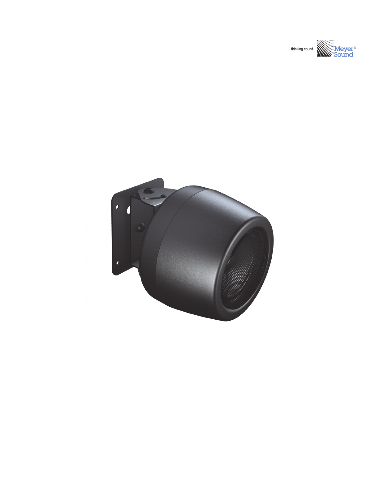
Stella-4 Constellation Installation Loudspeaker
Stella-4C Constellation Installation Ceiling-Mount Loudspeaker
Stella-8C Constellation Installation Ceiling-Mount Loudspeaker
Stella-188 Power Supply
ULTRA
Keep these important operating instructions.
Check www.meyersound.com for updates.
Page 2

© 2011, 2015
Meyer Sound. All rights reserved.
Stella Operating Instructions, PN 05.161.005.01 B3
The contents of this manual are furnished for informational purposes only, are subject to change without notice, and should not be construed as a commitment by Meyer Sound Laboratories Inc. Meyer Sound assumes no responsibility or liability for any errors or inaccuracies that may appear in this manual. Except as permitted by applicable copyright law, no part of this publication may be reproduced,
stored in a retrieval system, or transmitted, in any form or by any means, electronic, mechanical, recording or otherwise, without prior written permission from Meyer Sound.
Stella and all alpha-numeric designations for Meyer Sound products and accessories are trademarks of Meyer Sound. Constellation,
Meyer Sound, and the Meyer Sound wave logo are registered trademarks of Meyer Sound Laboratories Inc. (Reg. U.S. Pat. & Tm. Off.).
All third-party trademarks mentioned herein are the property of their respective trademark holders.
ii
Page 3

FEDERAL COMMUNICATIONS COMMISSION (FCC) STATEMENT
This equipment has been tested and found to comply with the limits for a Class A digital device, pursuant to part 15 of the
FCC Rules. These limits are designed to provide reasonable protection against harmful interference when the equipment is
operated in a commercial environment. This equipment generates, uses, and can radiate radio frequency energy and, if not
installed and used in accordance with the instruction manual, may cause harmful interference to radio communications.
Operation of this equipment in a residential area is likely to cause harmful interference in which case the user will be required
to correct the interference at their own expense.
This device complies with Part 15 of the FCC rules. Operation is subject to the following two conditions: (1) this device may
not cause harmful interference, and (2) this device must accept any interference received, including interference that may
cause undesired operation.
INDUSTRY CANADA COMPLIANCE STATEMENT
This Class A digital apparatus complies with Canadian ICES-003.
AVIS DE CONFORMITÉ À LA RÉGLEMENTATION D'INDUSTRIE CANADA
Cet appareil numérique de la classe A est conforme à la norme NMB-003 du Canada.
EN 55032 (CISPR 32) STATEMENT
Warning: This equipment is compliant with Class A of CISPR 32. In a residential environment this equipment may cause
radio interference.
iii
Page 4

iv
Page 5

CONTENTS
Chapter 1: Introduction 7
How to Use this Manual 7
Stella Loudspeakers 7
Stella Installation Loudspeaker 7
Stella-4C Installation Loudspeaker 8
Stella-8C Installation Loudspeaker 8
Stella-188 Power Supply 8
Chapter 2: Connecting Stella Loudspeakers 9
Stella Connector 9
Wiring Stella Loudspeaker Cables with Belden 1502 Cable (or Equivalent) 9
Stella-188 Power Supply 10
Stella-188 Front Panel 10
Stella-188 Rear Panel 10
Connecting Stella Loudspeakers to the Stella-188 14
Chapter 3: Stella Mounting Options 17
Important Safety Considerations 17
Using a Safety Cable with the Stella-4 17
Mounting the Stella-4 17
Mounting the Stella-4 with the MMB Bracket 18
Mounting the Stella-4 with the MMB Bracket and OmniMount 20.5 ST 18
Mounting the Stella-4 with the MAMB Adjustable Bracket 18
Mounting the Stella-4C 19
Installing the Stella-4C in a Backbox 19
Mounting the Stella-8C 20
Installing the Stella-8C in a Backbox 20
Appendix A: Stella Specifications 21
v
Page 6

CONTENTS
vi
Page 7
CHAPTER 1: INTRODUCTION
!
HOW TO USE THIS MANUAL
Make sure to read these operating instructions in their
entirety before configuring a system with Stella™ loudspeakers. In particular, pay close attention to material
related to safety issues.
As you read these operating instructions, you will encounter
the following icons for notes, tips, and cautions:
NOTE: A note identifies an important or useful
piece of information relating to the topic under
discussion.
TIP: A tip offers a helpful tip relevant to the topic
at hand.
CAUTION: A caution gives notice that an
action may have serious consequences and
could cause harm to equipment or personnel, and
could cause delays or other problems.
Information and specifications are subject to change.
Updates and supplementary information are available at
www.meyersound.com
.
STELLA LOUDSPEAKERS
The Stella family of loudspeakers was engineered primarily
®
for use in Meyer Sound’s Constellation
electroacoustic
architecture. The compact, self-powered loudspeakers are
ideally suited for applications requiring exceptional audio
performance, uniform directional control, low-profile mounting solutions, and remote power supplies.
Stella loudspeakers include onboard amplification and processing and exhibit the same high intelligibility, low distortion, and flat frequency and phase responses as other Meyer
Sound loudspeakers.
Stella Installation Loudspeaker
The Stella-4 installation loudspeaker is comprised of a
4-inch cone transducer housed in a compact aluminum die
cast enclosure. It delivers an impressive frequency range of
100 Hz to 18 kHz and a maximum peak SPL of 108 dB at
1 meter.
Meyer Sound Technical Support is available at:
■ Te l: +1 510 486.1166
■ Te l: +1 510 486.0657 (after hours support)
■ Web: www.meyersound.com/support
■ Email: techsupport@meyersound.com
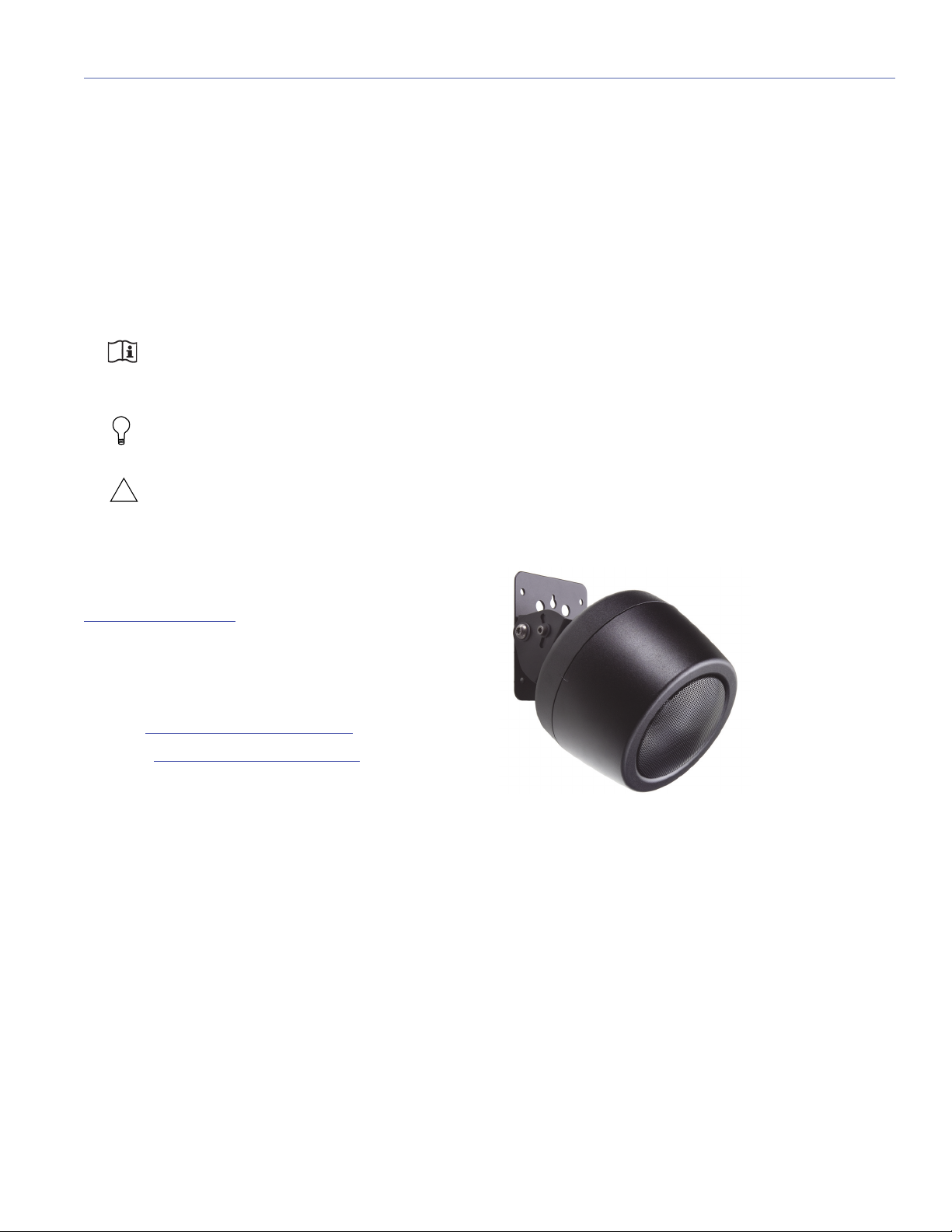
Stella-4 Loudspeaker Mounted with MAMB Adjustable Bracket
The Stella-4 can be easily mounted on ceilings or walls with
mounting accessories available from Meyer Sound and
third-party manufacturers.
7
Page 8
CHAPTER 1: INTRODUCTION
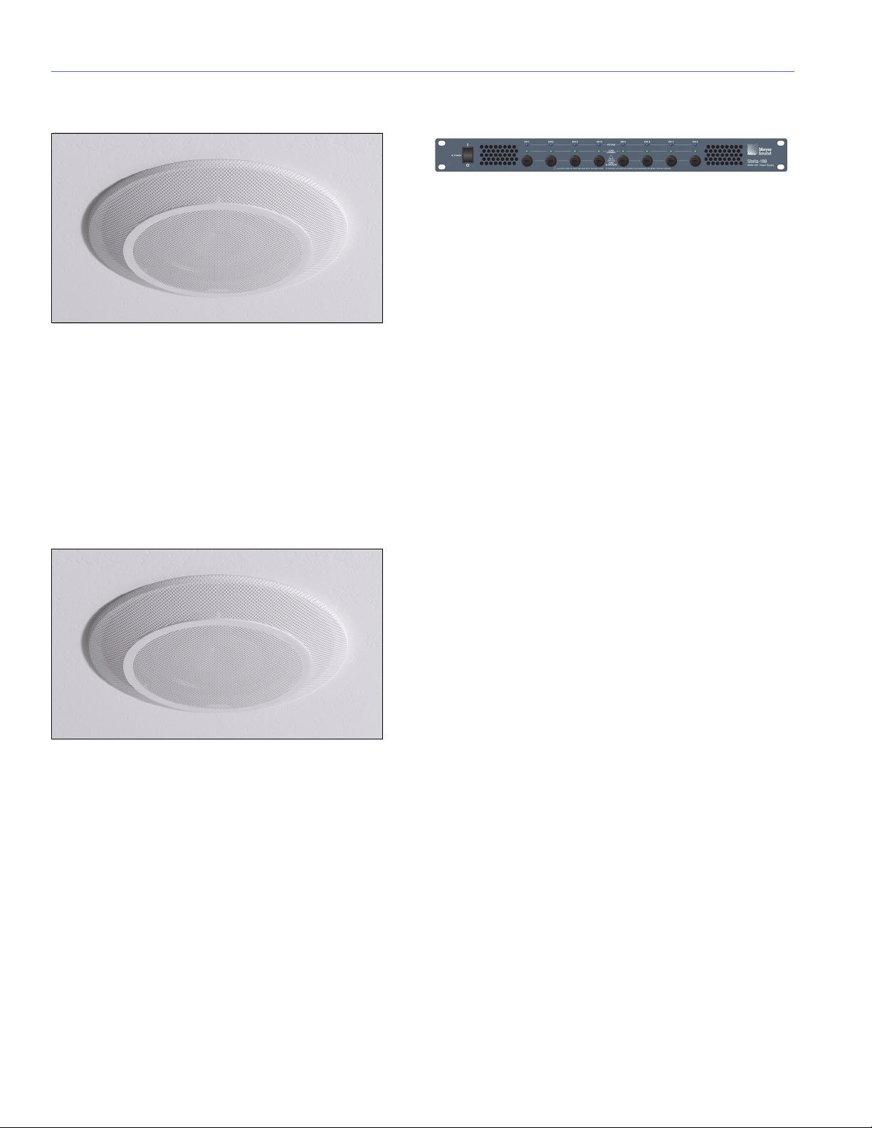
Stella-4C Installation Loudspeaker
Stella-4C Ceiling Mount Installation Loudspeaker
The Stella-4C ceiling mount installation loudspeaker offers
the same sonic capabilities as the Stella-4 in a package specifically designed for flushmount ceiling and wall applications, where it can be mounted in standard backboxes for
8-inch drivers (with a minimum depth of 6.5 inches). The
Stella-4C is housed in an aluminum die cast enclosure with
a rear heat sink.
Stella-8C Installation Loudspeaker
Stella-188 Power Supply
Stella-188 Power Supply
The required method of delivering DC power and balanced
audio to Stella loudspeakers is with the Stella-188 power
supply. The single-space rack unit can power up to 16
Stella-4 or Stella-4C loudspeakers, or up to eight Stella-8C
loudspeakers. The Stella-188 receives eight channels of balanced audio from its 25-pin D-sub connector and outputs
the audio, along with 18 V of DC power, to its five-pin Phoenix connectors. Each Channel Output can drive up to two
Stella-4/Stella-4C loudspeakers (or one Stella-8C loudspeaker). The Stella-188 front panel has LEDs for monitoring
voltage output and connectivity to the Stella loudspeakers.
Stella loudspeakers receive balanced audio and DC power
from a five-pin Phoenix-style connector on their rear panel.
Meyer Sound's patented Iso-Input™ transformer-isolated
differential inputs yield a high common-mode signal rejection ratio (CMRR). Because Stella loudspeakers have been
optimized to tolerate voltage drops of up to 30 percent, they
can accommodate light-gauge cables and long cable runs.
Stella-8C Ceiling Mount Installation Loudspeaker
The Stella-8C ceiling mount installation loudspeaker delivers
similar acoustical performance as the Stella-4 and Stella-4C
but with expanded output capability and wider coverage.
The unit's 8-inch coaxial cone and 0.75-inch tweeter transducers produce a maximum peak SPL of 117 dB at 1 meter
over a wide frequency range of 100 Hz to 18 kHz. Housed in
an aluminum, die cast enclosure with a rear heat sink, the
Stella-8C can be flush-mounted in ceilings and walls with
standard backboxes for 8-inch drivers (with a minimum
depth of 6.5 inches).
8
Page 9
CHAPTER 2: CONNECTING STELLA LOUDSPEAKERS
!
!
!
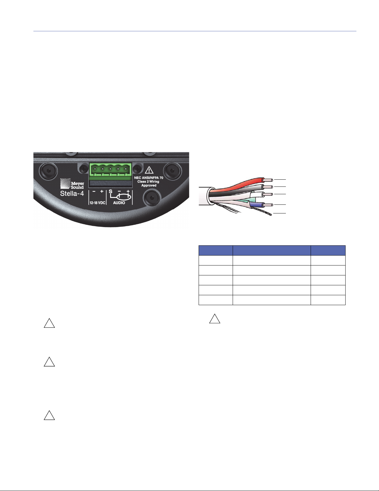
Red: DC power (+)
Black: DC power (–)
White: audio (+)
Blue: audio (–)
Shield drain: audio shield
!
STELLA CONNECTOR
Stella loudspeakers receive DC power and balanced audio
from a five-pin Phoenix connector on their rear panel. The
connector’s five pins include two for DC power (negative
and positive) and three for balanced audio (shield, negative,
and positive). These pins are clearly labeled on the Stella
rear panel. The connector accepts conductors up to
12 AWG (American Wire Gauge) or 2.5 mm
properly, Stella loudspeakers require DC power in the range
of 12–18 V DC.
Stella Connector
A single composite cable (such as Belden 1502R) wired for
both DC power and balanced audio can connect each Stella
loudspeakers to one of the Stella-188’s eight Channel Outputs.
Each Stella loudspeaker comes with one Phoenix cable
connector for making loudspeaker cables. For information
on cable requirements, see “Cable Lengths and Cable
Gauges for Stella Loudspeakers” on page 14.
CAUTION: Do not connect Stella loudspeakers
to voltages above 18 V DC. Receiving voltages
above 18 V DC will permanently damage Stella loudspeakers.
CAUTION: For installations comprising both
Stella loudspeakers and 48 V DC loudspeakers, make sure that Stella loudspeakers are only connected to a Stella-188 power supply. Connecting
Stella loudspeakers to a 48 V DC power supply will
permanently damage the Stella loudspeakers.
2
. To function
Wiring Stella Loudspeaker Cables with Belden 1502 Cable (or Equivalent)
The most convenient method of wiring Stella loudspeaker
cables is with a multiconductor cable such as Belden 1502,
which has dedicated conductors for DC power and balanced audio in a single jacket. When wiring Stella loudspeaker cables with Belden 1502, use the conventions in
Table 1. The red and black wires are 18 AWG, thicker than
the other three wires, and should be used for DC power (for
maximum cable lengths, see “Cable Lengths and Cable
Gauges for Stella Loudspeakers” on page 14). The blue,
white, and shield drain wires are shielded together and
should be used for audio.
Belden 1502 Composite Cable
Table 1: Wiring Stella Loudspeaker Cables with Belden 1502R
Wire Signal Gauge
Red DC power, positive (+) 18 AWG
Black DC power, negative (–) 18 AWG
White Balanced audio, positive (+) 22 AWG
Blue Balanced audio, negative (–) 22 AWG
Shield drain Balanced audio, shield 24 AWG
CAUTION: When wiring Stella loudspeaker
cables, it is extremely important that each pin
be wired correctly. Make sure the DC from the external power supply is wired directly (and only) to the DC
pins on the Stella loudspeaker connector, and that
the polarity is observed (negative to negative, positive
to positive) to avoid damage to the loudspeaker. In
addition, make sure that audio pins are wired correctly; polarity reversals for audio signals affect system performance.
CAUTION: When wiring Stella loudspeaker
cables, make sure each pin in the connector is
wired correctly to avoid damage to the loudspeaker
and polarity reversal, which can affect system performance.
9
Page 10

CHAPTER 2: CONNECTING STELLA LOUDSPEAKERS
STELLA-188 POWER SUPPLY
The Stella-188 was designed to deliver eight channels of
balanced audio and DC power to up to 16 Stella-4/Stella-4C
loudspeakers (or to up to eight Stella-8C loudspeakers). The
Stella-188 is a switched-mode, regulated power supply that
occupies one space in a standard 19-inch rack.
Stella-188 Front Panel
The Stella-188 front panel includes a power switch, LEDs for
monitoring each of the eight loudspeaker channels, and a
fuse for each channel.
Stella-188 Power Supply Front Panel
AC Power
The Stella-188 is powered on and off with the AC Power
switch.
Voltage and Load Current LEDs (1–8)
The Voltage and Load Current LEDs are useful for verifying
whether each of the eight Channel Outputs have voltage
and whether their connected loudspeakers are receiving DC
power and audio.
Voltage LEDs (1–8)
The blue Voltage LEDs indicate whether voltage is present
for each of the eight loudspeaker channels. These LEDs
should be lit when the Stella-188 is powered on. If a channel
is not lit, its fuse may need to be replaced. If a group of four
Voltage LEDs is not lit (either 1–4 or 5–9), one of the
Stella-188's two internal power supplies may have failed.
Load Current LEDs (1–8)
The green Load Current LEDs indicate whether a loudspeaker is connected to the channel and receiving power.
As a channel's audio signal increases, its LED becomes
brighter. If an LED is not lit, check that the channel's Voltage
LED is lit (the fuse is working) and verify the cable connection to the loudspeaker.
Fuse Slow Blow (1–8)
Each loudspeaker channel is protected by its own fuse. A
maximum of two Stella-4/Stella-4C loudspeakers (or one
Stella-8C loudspeaker) can be connected per channel; connecting more than that could cause the fuse to blow. When
replacing a fuse, make sure to use a 4-amp, 250-volt slowblow fuse (T4A-250V). These fuses are available from Meyer
Sound (PN 420.022).
Stella-188 Rear Panel
The Stella-188 rear panel includes an AC connector, an
Audio Input connector for receiving up to eight channels of
source audio, and eight Channel Output connectors that can
deliver DC power and balanced audio to up to 16 Stella-4/
Stella-4C loudspeakers (or to up to eight Stella-8C loudspeakers).
Stella-188 Channel LEDs and Fuses
10
Stella-188 Power Supply Back Panel
AC Input
The Stella-188 has an international standard IEC-320 AC
inlet (line, neutral/line, earth). The inlet can accept different
power cord types for outlets used throughout the world.
Make sure to use the correct power cord for the AC power in
your area. The Stella-188 operates at an AC voltage range of
100–240 V at 50–60 Hz.
Page 11

STELLA OPERATING INSTRUCTIONS
Stella-188 Current Draw
The current draw for the Stella-188 is dynamic and fluctuates as operating levels change for the connected loudspeakers. Since different cables and circuit breakers heat up
at varying rates, it is important to understand the following
types of current ratings and how they affect circuit breaker
and cable specifications.
■ Idle Current — The maximum rms current during idle
periods.
■ Maximum Long-Term Continuous Current — The
maximum rms current during a period of at least 10 seconds. The Maximum Long-Term Continuous Current is
used to calculate temperature increases for cables, to
ensure that cable sizes and gauges conform to electrical
code standards. It is also used as a rating for slow-reacting thermal breakers.
■ Burst Current — The maximum rms current during a
period of around one second. The Burst Current is used
as a rating for magnetic breakers. It is also used for calculating the peak voltage drop in long AC cable runs,
according to the following formula:
V pk (drop) = I pk x R (cable total)
■ Ultimate Short-Term Peak Current — A rating for fast-
reacting magnetic breakers.
■ Inrush Current — The spike of initial current encoun-
tered when powering on.
You can use the following tables as a guide for selecting circuit breaker ratings for the system’s operating voltage.
Current Draw for Stella-188 with Eight Stella-4s/Stella-4Cs
Current Draw
(Eight Stella-4s)
Idle Current 0.583 A rms 0.550 A rms 0.659 A rms
Maximum Long-Term
Continuous Current
Burst Current 2.40 A rms 1.40 A rms 2.80 A rms
Ultimate Short-Term
Current
Inrush Current 17.2 A peak 17.0 A peak 18.4 A peak
115
V AC
2.20 A rms 1.20 A rms 2.50 A rms
6.80 A peak 3.50 A peak 7.60 A peak
230
V AC
100
V AC
Current Draw for Stella-188 with 16 Stella-4s/Stella-4Cs
Current Draw
(16 Stella-4s)
Idle Current 0.943 A rms 0.751 A rms 1.078 A rms
Maximum Long-Term
Continuous Current
Burst Current 5.20 A rms 3.0 0A rms 6.70 A rms
Ultimate Short-Term
Current
Inrush Current 17.2 A peak 17.0 A peak 18.4 A peak
Current Draw for Stella-188 with Eight Stella-8Cs
Current Draw
(Eight Stella-8Cs)
Idle Current 0.943 A rms 0.751 A rms 1.078 A rms
Maximum Long-Term
Continuous Current
Burst Current 5.20 A rms 3.00 A rms 6.70 A rms
Ultimate Short-Term
Current
Inrush Current 17.2 A peak 17.0 A peak 18.4 A peak
115
V AC
4.50 A rms 2.15 A rms 5.50 A rms
13.0 A peak 9.0 A peak 15.0 A peak
115
V AC
4.50 A rms 2.15 A rms 5.50 A rms
13.0 A peak 9.0 A peak 15.0 A peak
230
V AC
230
V AC
100
V AC
100
V AC
The minimum electrical service amperage required by the
Stella-188 is the sum of the Maximum Long-Term Continuous Current for all loudspeakers connected to the
Stella-188. An additional 30 percent above the minimum
amperage is recommended to prevent peak voltage drops at
the service entry.
NOTE: For best performance, the AC cable
voltage drop should not exceed 10 V, or
10 percent at 115 V and 5 percent at 230 V. Make
sure that even with AC voltage drops that the AC
voltage always remains within the operating window.
11
Page 12

CHAPTER 2: CONNECTING STELLA LOUDSPEAKERS
Earth ground
Chassis ground
Safety Issues
Pay close attention to these important electrical and safety
issues.
■ The Stella-188 requires a grounded outlet.
■ Do not use a ground-lifting adapter or cut the AC cable
ground pin.
Audio Input
Up to eight channels of balanced audio are received via the
Stella-188’s Audio Input connector. Each of the eight audio
channels is hard-wired to the corresponding Stella-188
Channel Outputs, thereby allowing for easy distribution of
discrete audio channels for Constellation installations.
Stella-188 Audio Input
The Audio Input connector requires either a 25-pin D-sub to
8-channel audio snake, or 25-pin D-sub to D-sub cable for
connecting directly to audio processors.
Meyer Sound manufactures the following cables that can be
used with the Stella-188 Audio Input connector (for more
information, contact Meyer Sound).
■ D-sub male to D-sub male cable, 0.5 meters
(PN 28.167.012.01)
■ D-sub male to D-sub male cable, 1 meter
(PN 28.167.012.02)
■ Keep all liquids away from the Stella-188 to avoid haz-
ards from electrical shock.
■ Do not operate the unit if the power cables are frayed or
broken.
■ D-sub male to D-sub male cable, 2 meters
(PN 28.167.012.03)
■ D-sub male to XLR female cable, 10 feet
(PN 28.139.009.01)
You can also make your own audio cables for connecting to
the Stella-188. The Audio Input connector uses the following
Tascam DA-88 wiring scheme.
Table 2: Pin Outputs for Stella-188 Audio Input Connector
Channel
Number
1 D-sub 25 D-sub 24 D-sub 12
2 D-sub 11 D-sub 10 D-sub 23
3 D-sub 22 D-sub 21 D-sub 9
4 D-sub 8 D-sub 7 D-sub 20
5 D-sub 19 D-sub 18 D-sub 6
6 D-sub 5 D-sub 4 D-sub 17
7 D-sub 16 D-sub 15 D-sub 3
8 D-sub 2 D-sub 1 D-sub 14
XLR Pin 1
(Chassis)
XLR Pin 2
(Hot)
XLR Pin 3
(Cold)
12
Page 13

STELLA OPERATING INSTRUCTIONS
!
Channel Outputs (1–8)
The eight Channel Outputs deliver DC power (18 V DC) and
balanced audio to up to eight loudspeaker channels. Each
Channel Output can drive up to two Stella-4/Stella-4C loudspeakers (or one Stella-8C loudspeaker). The Channel Outputs use five-pin Phoenix connectors with three pins for
balanced audio (positive, negative, and shield) and two for
DC Power (positive and negative). These pins are clearly
labeled on the Stella-188 back panel.
Stella-188 Channel Outputs
A single composite cable (such as the Belden 1502R) wired
for both DC power and balanced audio can be used to connect to loudspeakers. Each Stella-188 comes with Phoenix
cable connectors for creating Stella loudspeaker cables. For
information on cable requirements, see “Cable Lengths and
Cable Gauges for Stella Loudspeakers” on page 14.
CAUTION: When wiring cable connections for
the Stella-188 Channel Outputs, make sure
each pin in the connector is wired correctly to avoid
damage to the loudspeaker and polarity reversal,
which can affect system performance.
Current Draw for Stella-4 and Stella-4C Loudspeakers
The Stella-4 and Stella-4C draw a maximum current of 1.5 A
rms and 3.3 A peak. Their current draw is dynamic and fluctuates as volume levels change. The cabling between the
Stella loudspeakers and the Stella-188 adds resistance and
hence causes a voltage drop at the loudspeakers. Because
lower voltages compromise peak SPL, and in some cases
frequency response, cable resistance should be minimized.
NOTE: When connecting a single Stella-4 or
Stella-4C to a Stella-188 Channel Output, the
total cable resistance should not exceed 4 ohms.
When connecting two Stella-4s or two Stella-4Cs to a
Stella-188 Channel Output, the total cable resistance
should not exceed 2 ohms.
Current Draw for Stella-8C Loudspeakers
The Stella-8C draws a maximum current of 3.1 A rms and
6.3 A peak. Its current draw is dynamic and fluctuates as
volume levels change. The cabling between the Stella-8C
Stella-188 adds resistance and hence causes a voltage drop
at the loudspeaker. Because lower voltages compromise
peak SPL, and in some cases frequency response, cable
resistance should be minimized.
NOTE: When connecting the Stella-8C to a
Stella-188 Channel Output, the total cable
resistance should not exceed 2 ohms.
Number of Stella Loudspeakers per Stella-188 Channel
Output
Each Stella-188 Channel Output can drive the following
Stella loudspeaker configurations:
■ One or two Stella-4 loudspeakers
■ One or two Stella-4C loudspeakers
■ One Stella-4 loudspeaker and one Stella-4C loudspeaker
■ One Stella-8C loudspeaker
TIP: To connect two Stella-4s or two Stella-4Cs
to a single Stella-188 Channel Output, daisychain the cable of the first Stella loudspeaker to the
second. Wire the cable connector plugged into the
first Stella with both the cable connected to the
Stella-188 and the cable connected to the second
Stella (see Figure 2 on page 15).
13
Page 14

CHAPTER 2: CONNECTING STELLA LOUDSPEAKERS
Cable Lengths and Cable Gauges for Stella
Loudspeakers
When connecting a single Stella-4 or Stella-4C to a
Stella-188 Channel Output, you can use cable lengths up to
300 feet with only 1 dB of peak SPL loss with 18 AWG wire.
When connecting two Stella-4s or Stella-4Cs (or one
Stella-8C), equivalent lengths are possible with heavier wire
gauges (see Table 3 and Table 4).
Table 3: Stella Loudspeaker Cable Lengths (AWG)
Cable
Gauge
12 AWG 0.0016 1200 ft 600 ft 600 ft
14 AWG 0.00253 750 ft 375 ft 375 ft
16 AWG 0.00402 475 ft 237 ft 237 ft
18 AWG 0.00636 300 ft 150 ft 150 ft
20 AWG 0.01008 175 ft 87 ft 87 ft
Table 4: Stella Loudspeaker Cable Lengths (European)
Cable
Gauge
2.50 mm
1.50 mm20.01076 175 m 87 m 87 m
1.00 mm
0.75 mm
Cable
Resistance
(/ft)
Cable
Resistance
(/m)
2
0.0052 365 m 157 m 157 m
2
0.02087 90 m 45 m 45 m
2
0.03307 55 m 27 m 27 m
Approximate Maximum Cable Length
1 Stella-4 /
Stella-4C
per Chan.
Approximate Maximum Length
1 Stella-4 /
Stella-4C
per Chan.
2 Stella-4s /
Stella-4Cs
per Chan.
2 Stella-4s
/ Stella-4Cs
per Chan.
1 Stella-8C
per
Chan.
1 Stella-8C
per
Chan.
CONNECTING STELLA LOUDSPEAKERS TO THE STELLA-188
To connect Stella loudspeakers to the Stella-188:
1. Power off the Stella-188.
2. Attach a 25-pin D-sub audio cable or snake to the
Stella-188 Audio Input connector. This cable should use
the Tascam DA-88 wiring scheme (see Table 2 on
page 12).
3. Connect audio sources (from a mixer or processor) to the
other end of the audio cable or snake.
4. Connect Stella loudspeakers to the Stella-188 Channel
Outputs. Use composite cables (such as Belden 1502R)
wired for both DC power and balanced audio outfitted
with five-pin Phoenix connectors.
■ Connect up to 16 Stella-4s or Stella-4Cs to the
Stella-188.
■ Connect up to eight Stella-8Cs to the Stella-188.
The maximum cable length for a single Stella-4 or Stella-4C
can be calculated with the following formula:
maximum length = 4 ohms / 2 * cable resistance
For example, the maximum length for 18 AWG cable with a
resistance of 0.00636 ohms/ft is 314.4 feet (4 / 2 * 0.00636).
If you are using two Stella-4s or two Stella-4Cs (or one
Stella-8C), the distance is reduced by half to 157.2 feet,
since the maximum cable resistance for two Stella-4s/
Stella-4Cs (or one Stella-8C) is 2 ohms.
NOTE: For long cable runs, you can use large
cable gauges for most of the run and then terminate with the appropriate gauge (see Table 3 and
Table 4) at the connector.
14
NOTE: For maximum cable lengths for the
Stella loudspeakers, refer to Table 3 on
page 14 and Table 4 on page 14.
5. Enable output from the audio sources (from a mixer or
processor) connected to the Stella-188.
6. Power on the Stella-188 and monitor the LEDs on its
front panel to verify connections.
Page 15

Figure 1: Stella-188 with Eight Stella-4s (One Unit Connected to Each Channel Output)
STELLA OPERATING INSTRUCTIONS
Figure 2: Stella-188 with 16 Stella-4s (Two Units Connected to Each Channel Output)
Figure 3: Stella-188 with Eight Stella-4s (Two Units Connected to Outputs 1, 2, 7, and 8) and Four Stella-8Cs (One Unit Connected to Outputs 3–6)
15
Page 16

CHAPTER 2: CONNECTING STELLA LOUDSPEAKERS
16
Page 17

CHAPTER 3: STELLA MOUNTING OPTIONS
Threaded hole for safety
cable attachment
IMPORTANT SAFETY CONSIDERATIONS
When installing Meyer Sound loudspeakers, the following
precautions should always be observed:
■ All Meyer Sound products must be used in accordance
with local, state, federal, and industry regulations. It is
the owner's and user's responsibility to evaluate the reliability of any rigging method for their application. Rigging
should only be carried out by experienced professionals.
■ Use mounting and rigging hardware that has been rated
to meet or exceed the weight being hung.
■ Use mounting hardware appropriate for the surface
where the loudspeaker will be installed.
■ Make sure bolts and eyebolts are tightened securely.
®
Meyer Sound recommends using Loctite
on eyebolt
threads and safety cables.
■ Inspect rigging hardware regularly and immediately
replace worn or damaged components.
Using a Safety Cable with the Stella-4
Meyer Sound recommends attaching a safety cable to the
Stella-4 before installation. This ensures the loudspeaker will
not accidentally fall during installation, and it provides additional safeguards for the loudspeaker if for some reason its
mounting hardware fails.
MOUNTING THE STELLA-4
The Stella-4 can be mounted with the following bracketing
options:
■ The MMB bracket mounts the Stella-4 on a wall, ceiling,
or single-gang electrical back box. You can also use the
MMB to mount the Stella-4 with other third-party options
like the OmniMount 20.5 ST.
Stella-4 MMB Bracket
■ The MAMB adjustable bracket mounts the Stella-4 on a
wall, ceiling, or single-gang electrical back box. In addition, the MAMB allows the Stella-4's position to be
adjusted up to 45 degrees in any direction.
Stella-4 Safety Cable Attachment
A safety cable attachment is included with the Stella-4. The
attachment includes a metal loop, screw, and two washers
that screw into the back of the Stella-4. Once the safety
cable attachment is securely installed, a safety cable (not
included) can be attached to it.
Stella-4 MAMB Adjustable Bracket
NOTE: Both the MMB and MAMB brackets
ship with grommets installed in the four corner
holes of the loudspeaker plates. These grommets
absorb vibrations between the mounting surface and
the Stella-4 loudspeaker and should not be removed.
17
Page 18

CHAPTER 3: STELLA MOUNTING OPTIONS
Mounting the Stella-4 with the MMB Bracket
To mount the Stella-4 with the MMB bracket:
1. Separate the MMB wall plate from the MMB loudspeaker
plate by unscrewing the thumbscrew.
2. Mount the MMB wall plate to the wall with one of the following options. Position the wall plate so its hinges are
pointing up.
■ Mount directly to the wall surface using screws in the
four corner holes. Use fastening hardware appropriate
for the mounting surface.
■ Mount on a single-gang electrical back box using screws
in the two center holes (top and bottom).
3. Attach the MMB loudspeaker plate to the back of the
Stella-4 using screws in the four corner holes. The loudspeaker plate should be positioned parallel to the heat
sink grooves on the back of the Stella-4 (so the Stella-4's
Phoenix connector is not covered).
3. Attach the OmniMount mounting plate to the MMB loudspeaker plate using screws in the two center holes (top
and bottom).
4. Attach the mounting plate to the OmniMount ball-clamp
assembly according to the manufacturer's instructions.
Mounting the Stella-4 with the MAMB Adjustable Bracket
To mount the Stella-4 with an MAMB adjustable bracket:
1. Separate the MAMB wall plate from the pivot plate
assembly by removing the center screw and washers.
4. Attach the loudspeaker plate to the wall mount using the
hinges and tighten the thumbscrew with a screwdriver
(but don't over-tighten it).
Mounting the Stella-4 with the MMB Bracket and OmniMount 20.5 ST
To mount the Stella-4 with an MMB bracket and OmniMount
20.5 ST:
1. Separate the MMB wall plate from the MMB loudspeaker
plate by unscrewing the thumbscrew.
2. Attach the MMB loudspeaker plate to the back of the
Stella-4 using screws in the four corner holes. The loudspeaker plate should be positioned parallel to the heat
sink grooves on the back of the Stella-4 (so the Stella-4's
Phoenix connector is not covered).
2. Mount the MAMB wall plate to the wall with one of the
following options.
■ Mount directly to the wall surface using screws in the
four corner holes. Use fastening hardware appropriate
for the mounting surface.
■ Mount on a single-gang electrical back box using screws
in the two center holes (top and bottom).
3. Attach the MAMB pivot plate assembly to the Stella-4
using screws in the four corner holes. The pivot plate
assembly should be positioned parallel to the heat sink
grooves on the back of the Stella-4 (so the Stella-4's
Phoenix connector is not covered).
18
Page 19

STELLA OPERATING INSTRUCTIONS
Backbox
Stella-4C
grille frame
Stella-4C
4. Attach the pivot plate assembly to the wall plate using
the screw and washers previously removed. Tighten the
screw.
5. To adjust the position of the Stella-4, loosen the four
pivot plate screws and position the Stella-4 as necessary. Tighten the pivot plate screws to secure the
Stella-4.
MOUNTING THE STELLA-4C
The Stella-4C can be mounted flush in ceilings and walls
with any standard 8-inch backbox (such as the Atlas
BMT95-8-7, Lowell CP-87 or XCP-87) with a minimum
depth of 6.5 inches.
Installing the Stella-4C in a Backbox
To install the Stella-4C in a standard 8-inch backbox:
1. Mount the backbox in the ceiling or wall according to the
manufacturer's instructions.
2. Place the Stella-4C in the backbox and secure it with the
8-32 screws included with the Stella-4C.
3. Attach the Stella-4C grille frame:
■ Screw the three threaded studs (included with the
Stella-4C) into the Stella-4C grille frame.
■ Attach the grille frame to the Stella-4C by inserting the
other ends of threaded studs into the three nylon latches
in the Stella-4C.
■ Gently push the grille frame in until it locks in place flush
with the wall or ceiling.
NOTE: The Stella-4C’s grille frame is held in
place with three nylon latches. To remove the
grille frame, gently pull it, evenly, until it releases from
the latches.
19
Page 20

CHAPTER 3: STELLA MOUNTING OPTIONS
Backbox
Stella-8C
grille frame
Stella-8C
MOUNTING THE STELLA-8C
The Stella-8C can be mounted flush in ceilings and walls
with any standard 8-inch backbox (such as the Atlas
BMT95-8-7, Lowell CP-87 or XCP-87) with a minimum
depth of 6.5 inches.
Stella-8C Mounted in Third-Party Backbox
Installing the Stella-8C in a Backbox
To install the Stella-8C in a standard 8-inch backbox:
■ Gently push the grille frame in until it locks in place flush
with the wall or ceiling.
NOTE: The Stella-8C’s grille frame is held in
place with three nylon latches. To remove the
grille frame, gently pull it, evenly, until it releases from
the latches.
1. Mount the backbox in the ceiling or wall according the
manufacturer's instructions.
2. Place the Stella-8C in the backbox and secure it with the
8-32 screws included with the Stella-8C.
3. Attach the Stella-8C grille frame:
■ Screw the three threaded studs (included with the
Stella-8C) into the Stella-8C grille frame.
■ Attach the grille frame to the Stella-8C by inserting the
other ends of threaded studs into the three nylon latches
in the Stella-8C.
20
Page 21

APPENDIX A: STELLA SPECIFICATIONS
6.33
[161mm]
5.32
[135mm]
2.00
[51mm]
2.00
[51mm]
5.39
[137mm]
STELLA-4 SPECIFICATIONS
Operating Frequency Range 100 Hz – 18 kHz
Note: Recommended maximum operating frequency range. Response depends on loading conditions and
room acoustics.
Frequency Response 115 Hz – 16 kHz ±4 dB
Note: Measured free-field with pink noise at 1 meter, 1/3rd octave resolution.
Maximum Peak SPL 108 dB (free field, measured with music referred to 1 meter)
Note: Measured free-field with music and referred to 1 meter.
Phase Response 250 Hz – 18 kHz ±30°
Coverage 60° (3 kHz – 13 kHz ±10°); 120° (below 2 kHz)
Transducer One 4” cone driver
Voltage Requirement 12–18 V DC
Audio/Power Connector Single 5-pin Phoenix (3 pins for balanced audio, 2 pins for DC power)
Input Impedance 20 k balanced internal isolation (Iso-Input) transformer
Nominal Input Sensitivity +6 dBV (2.0 V rms, 2.8 V peak) continuous average is typically the onset of limiting for noise and music
Input Level Audio source must be capable of delivering +15 dBV (5.6 V rms, 8.0 V peak) into 600 to produce the
maximum peak SPL over the loudspeaker’s operating bandwidth
Current Draw 1.5 A average; 3.3 A peak
Noise Floor < 20 dB A weighted
Dimensions 5.39” (front OD) x 6.33” (max OD) x 5.32” D
137 mm (front OD) x 161 mm (max OD) x 135 mm D
Weight 5.0 lbs (2.27 kg)
Stella-4 Dimensions
21
Page 22

APPENDIX A: STELLA SPECIFICATIONS
Ø13.23
[Ø336.02mm]
7.95
[202.06mm]
11.25
[285.75mm]
Ø0.22
[Ø5.50mm]
1.40
[35.56mm]
6.33
[160.78mm]
5.12
[129.94mm]
11.75
[298.42mm]
4.00
[101.60mm]
10.00
[254.00mm]
6.53
[165.92mm]
1.35
[34.42mm]
7.89
[200.33mm]
STELLA-4C SPECIFICATIONS
Operating Frequency Range 100 Hz – 18 kHz
Note: Recommended maximum operating frequency range. Response depends on loading conditions and
room acoustics.
Frequency Response 115 Hz – 16 kHz ±4 dB
Note: Measured free-field with pink noise at 1 meter, 1/3rd octave resolution.
Maximum Peak SPL 108 dB
Note: Measured free-field with music and referred to 1 meter.
Phase Response 250 Hz – 18 kHz ±30°
Coverage 60° (3 kHz – 13 kHz ±10°); 120° (below 2 kHz)
Transducer One 4” cone driver
Voltage Requirement 12–18 V DC
Audio/Power Connector Single 5-pin Phoenix (3 pins for balanced audio, 2 pins for DC power)
Input Impedance 20 k balanced internal isolation (Iso-Input) transformer
Nominal Input Sensitivity +6 dBV (2.0 V rms, 2.8 V peak) continuous average is typically the onset of limiting for noise and music
Input Level Audio source must be capable of delivering +15 dBV (5.6 V rms, 8.0 V peak) into 600 to produce the
maximum peak SPL over the loudspeaker’s operating bandwidth
Current Draw 1.5 A average; 3.3 A peak
Noise Floor < 20 dB A weighted
Dimensions 11.75” (front OD) x 4.00” (depth without grille)
298.42 mm (front OD) x 101.60 mm (depth without grille)
Weight 6.0 lbs (2.72 kg) without backbox
Stella-4C Dimensions
22
Stella-4C with Typical Third-Party Backcan Dimensions
Page 23

STELLA-8C SPECIFICATIONS
Ø13.23
[Ø336.02mm]
11.25
[285.75mm]
7.95
[202.06mm]
Ø0.22
[Ø5.50mm]
8.72
[221.49mm]
6.29
[159.83mm]
1.40
[35.56mm]
5.47
[138.86mm]
11.66
[296.16mm]
Operating Frequency Range 100 Hz – 18 kHz
Note: Recommended maximum operating frequency range. Response depends on loading conditions and
room acoustics.
Frequency Response 115 Hz – 16 kHz ±4 dB
Note: Measured free-field with pink noise at 1 meter, 1/3rd octave resolution.
Maximum Peak SPL 117 dB
Note: Measured free-field with music and referred to 1 meter.
Phase Response 2 kHz – 18 kHz ±45°
Coverage 100°
Transducer One 8” coaxial cone driver; one 0.75” metal dome tweeter
Voltage Requirement 12–18 V DC
Audio/Power Connector Single 5-pin Phoenix (3 pins for balanced audio, 2 pins for DC power)
Input Impedance 20 k balanced internal isolation (Iso-Input) transformer
Nominal Input Sensitivity +6 dBV (2.0 V rms, 2.8 V peak) continuous average is typically the onset of limiting for noise and music
Input Level Audio source must be capable of delivering +15 dBV (5.6 V rms, 8.0 V peak) into 600 to produce the
maximum peak SPL over the loudspeaker’s operating bandwidth
Current Draw 3.1 A average; 6.3 A peak
Noise Floor <20 dB A weighted
Dimensions 11.66” (front OD) x 5.47” (depth without grille)
296.16 mm (front OD) x 138.86 mm (depth without grille)
Weight 9.0 lbs (4.1 kg) without backbox
STELLA OPERATING INSTRUCTIONS
Stella-8C Dimensions
23
Page 24

APPENDIX A: STELLA SPECIFICATIONS
19.00
[482.60mm]
16.90
[429.26mm]
13.57
[344.78mm]
14.07
[357.40mm]
1.73
[43.94mm]
STELLA-188 SPECIFICATIONS
Audio Input 8-channel 25-pin D-sub connector (Tascam Mulitrack format)
Outputs 8 channels of 5-pin Phoenix connectors (3 pins for balanced audio hard-wired to the D-sub input connector, 2 pins
for DC power)
Output Voltage 8 outputs of 18 V DC (4.0 A, fuse protected)
Front Panel On-off switch
8 LEDs to indicate output voltage
8 LEDs to indicate current
AC Connector Detachable IEC 320 (line, neutral/line, earth)
Current Draw
Idle Current 8 Stella-4s/Stella-4Cs (1 per channel) 0.583 A rms (115 V AC); 0.550 A rms (230 V AC); 0.659 A rms (100 V AC)
16 Stella-4s/Stella-4Cs (2 per channel) 0.943 A rms (115 V AC); 0.751 A rms (230 V AC); 1.078 A rms (100 V AC)
8 Stella-8Cs (1 per channel) 0.943 A rms (115 V AC); 0.751 A rms (230 V AC); 1.078 A rms (100 V AC)
Maximum Long-Term
Continuous Current
Burst Current 8 Stella-4s/Stella-4Cs (1 per channel) 2.40 A rms (115 V AC); 1.40 A rms (230 V AC); 2.80 A rms (100 V AC)
Ultimate Short-
Term Peak Current
Inrush Current 17.2 A peak (115 V AC); 17.0 A peak (230 V AC); 18.4 A peak (100 V AC)
Dimensions 1RU high
Weight 13.0 lbs (5.9 kg)
8 Stella-4s/Stella-4Cs (1 per channel) 2.20 A rms (115 V AC); 1.20 A rms (230 V AC); 2.50 A rms (100 V AC)
16 Stella-4s/Stella-4Cs (2 per channel) 4.50 A rms (115 V AC); 2.15 A rms (230 V AC); 5.50 A rms (100 V AC)
8 Stella-8Cs (1 per channel) 4.50 A rms (115 V AC); 2.15 A rms (230 V AC); 5.50 A rms (100 V AC)
16 Stella-4s/Stella-4Cs (2 per channel) 5.20 A rms (115 V AC); 3.00 A rms (230 V AC); 6.70 A rms (100 V AC)
8 Stella-8Cs (1 per channel) 5.20 A rms (115 V AC); 3.00 A rms (230 V AC); 6.70 A rms (100 V AC)
8 Stella-4s/Stella-4Cs (1 per channel) 6.80 A peak (115 V AC); 3.50 A peak (230 V AC); 7.60 A peak (100 V AC)
16 Stella-4s/Stella-4Cs (2 per channel) 13.0 A peak (115 V AC); 9.0 A peak (230 V AC); 15.0 A peak (100 V AC)
8 Stella-8Cs (1 per channel) 13.0 A peak (115 V AC); 9.0 A peak (230 V AC); 15.0 A peak (100 V AC)
19.00" W x 1.73" H x 13.57" D
(482.60 mm x 43.94 mm x 348.78 mm)
Stella-188 Dimensions
24
Page 25

Page 26

Page 27

Page 28

Meyer Sound Laboratories Inc.
2832 San Pablo Avenue
Berkeley, CA 94702
+1 510 486.1166
www.meyersound.com
Meyer Sound Laboratories Inc.
© 2011, 2015
Stella Operating Instructions, PN 05.161.005.01 B3
 Loading...