

Page 1

SEL INSTALLATION AND OPERATING INSTRUCTION MANUAL
SEL SERIES ELECTRIC
TAILGATE SPREADER
WWW.MEYERPRODUCTS.COM 00122-517-01 SEPTEMBER 2009
Page 2

SEL INSTALLATION AND OPERATING INSTRUCTION MANUAL
INCLUDED IN THIS MANUAL:
Safety Instructions-------------------------------------
Control
H
arness
Trough
Spinner
Spinner Spread Pattern
Operating Instructions ----------------------------------------------------------------Recommended Regular Maintenance---------------------------
Assembly Parts Drawing & Parts List ---------------------------------
Spinner Assembly Parts Drawing & Parts List ----------------------------------Name Plate Information --------------------------------------------------------------------------------Warranty----------------------------------------------------------------------------------------------------
Electric
and Wiring Diagram
mounting instructions
Assembly and
Specifications & Installation --------------------
Installation ------------------------------
Instructions ------------------------------
-------------------------------
-----------------------------------
--------------------------
-------
---------------------
------------------------
-----
-------------------------
----
-----------------------------
------------------------
------------
---
----------
---------------------------
---------------------
-----------
--------------
----
--------------
------------
----
-------------
----
-------------
- 3-5
6
7-
10-11
12-14
15-16
1
7-18
19
21-28
29-32
33
34
9
WWW.MEYERPRODUCTS.COM 00122-517-01 SEPTEMBER 2009
PAGE 2
Page 3

SEL INSTALLATION AND OPERATING INSTRUCTION MANUAL
SAFETY PRECAUTIONS
The best safety device is a careful operator!
This symbol means ATTENTION!
Become Alert!
Your safety is involved!
Please read and understand completely before doing!
BEFORE PERFORMING MAINTENANCE OPERATIONS, PARK VEHICLE ON LEVEL GROUND.
SET PARKING BRAKE, SHUT OFF ALL POWER, AND MAKE SURE ALL MOVEMENT HAS STOPPED.
IF BODY IS RAISED, IT MUST BE SECURELY BLOCKED SO IT CANNOT COME DOWN.
SUPPORT BLOCKS MUST NOT BE REMOVED UNTIL THERE IS NO DANGER OF ANYONE BEING UNDER BODY
WHEN BODY IS LOWERED.
Improper use of this equipment can result
in serious injury. To reduce this
possibility, give complete and undivided
attention to the job at hand, and follow these safety
precautions.
PREPERATION:
Know your controls. Read this instruction manual. Learn
how to stop the equipment quickly in an emergency.
Do not allow children to operate machine; nor adults to
operate it without proper instructions.
Keep all individuals not involved in the use of the
equipment a safe distance away.
A
copy of this manual should be available in the cab at all
times. A copy may be obtained from your local dealer or
.
OPERATION:
Do not exceed rated capacities of chassis or hoist.
Observe and shut off all equipment controls before
starting engine so equipment will not unintentionally
operate when engine is started.
A
lways check area around machine before engaging or
operating controls.
Vehicle should be on a flat surface prior to raising bed.
Operation on slippery uneven terrain may result in
equipment damage or personal injury.
Know the material you are hauling and plan your haul to
avoid “set up” or freezing of the load in the dump body.
In the event that a load becomes stuck or frozen in the
body, do not abuse, overload, or damage the truck, hoist,
or body in efforts to quickly free the load. It may be
necessary to thaw indoors to safely remove such a load.
In the event that shoveling or mechanical means are
used to free the stuck load, be sure the load is NOT
hoisted and the tailgate, if opened, is secured properly
before starting this effort. If hoisted, a stuck load, or
portion, could release unexpectedly and cause injury to
personnel or damage to the body, truck, or surroundings.
Some materials such as mud, or sludge, may shift easily
when wet, resulting in increased tendency to overturn the
truck on curves, unstable ground, or side slope situations.
Reduce load size, speeds, and side slopes, and use care
and planning to avoid this potential occurrence.
Unload the body and securely prop and block a raised
body before any service, inspection, or repair work is
started.
Be sure the PTO is disengaged before traveling. Failure
to disengage the PTO from driving the pump/valve when
in transit may allow the dump body to rise unintentionally.
This may lead to loss of vehicle control, accidental injury
and/or property damage.
Lift points are provided to safely lift body assembly.
Never lift or handle loaded body, empty material prior to
handling the body.
Always wear relatively tight and belted clothing when
operating equipment. Loose jackets, shirts sleeves or
other loose clothing should not be worn because of the
danger of catching them in moving parts or controls.
Stop and inspect equipment if unusual movement,
sounds, or noises are observed. Repair damage before
restarting and operating the equipment.
Disengage power to all operating equipment: (1) before
leaving operator’s position, (2) before making any repairs
or adjustments, or (3) when not in use.
Take all possible precautions when leaving the
equipment unattended; such as disengaging the
hydraulic system, shifting vehicle out of gear, setting
parking brake, shutting off engine and removing key.
Never leave raised body unattended.
download from www.
meyerproducts
.com
WWW.MEYERPRODUCTS.COM 00122-517-01 SEPTEMBER 2009
PAGE 3
Page 4

SEL INSTALLATION AND OPERATING INSTRUCTION MANUAL
This decal appears on the left end,
or the right end of the spreader
trough. It cautions all to observe
general safety procedures when
operating this equipment.
NOTICE!
Your spreader is equipped with a safety interlock device. This device must be
disconnected before the spreader trough bottom door and the spreader trough top
cover can be opened exposing the auger. This device positively disconnects all
contact with a turning auger.
This decal appears on the back of the
spreader cover plate at the right end of
the spreader. It alerts all to the danger
associated with the improper use of
the Safety Interlock Device.
This decal appears on the back of the spreader
trough cover plate. It alerts all to the danger of being
caught in the dropout opening or from the top of the
spreader trough where serious personal injury could
result.
This
decal appears near the spinner assembly on the
back of the spreader trough cover plate. It alerts all
to the danger of being struck by material being
spread by the spinner assembly which could result in
serious personal injury.
electric
power from the auger drive motor to prevent accidental bodily injury due to
WWW.MEYERPRODUCTS.COM 00122-517-01 SEPTEMBER 2009
PAGE 4
Page 5

SEL INSTALLATION AND OPERATING INSTRUCTION MANUAL
Stay clear while
spinner is turning
IF DEFACED - ORDER PART NO. 04049 044 00
DANGER
IF DEFACED - ORDER PART NO. 04049 121 00
DANGER
ORIGINAL INTENT AS SHOWN
IS ALTERED IN ANY WAY FROM ITS ORIGINAL INTENT AS SHOWN
IF THE SAFETY INTERLOCK DEVICE - AS INSTALLED ON THIS SPREADER:
IS NOT MAINTAINED SO AS TO OPERATE ACCORDING TO ITS
SERIOUS PERSONAL INJURY OR DEATH CAN RESULT
SPREADER WILL OPERATE
AND BOTTOM DOOR CANNOT BE OPENED
TOP COVER CANNOT BE OPENED REARWARD
BOTTOM DOOR
LATCH HANDLE IS FULLY CLOSED
EXPOSING AUGER
(CLOSED)
ELECTRICAL COUPLING CONNECTED
TOP COVER
SPREADER WILL NOT OPERATE
IF DEFACED - ORDER PART NO. 04049 411 00
TOP COVER CAN BE OPENED REARWARD
AND BOTTOM DOOR CAN BE OPENED
LATCH HANDLE CAN BE OPENED
(OPENED)
BOTTOM DOOR
ELECTRICAL COUPLING NOT CONNECTED
TOP COVER
5. USE FLASHING LIG HTS WHEN OPERATING MACHINE.
IF DEFACED - ORDER PART NO. 04049 045 00
6. MAKE SURE MACHI NE IS SOLIDLY SUPPORTED
WHEN IT IS BEIN G MOUNTED, DISMOUNTED,
OR STORED.
2. MAKE CERTAIN EV ERYONE IS CLEAR BEFORE
STARTING MACHIN E OR MOVING VEHICLE.
ALL POWER DRIVEN PARTS.
4. DISENGAGE PTO , SHUT OFF HYDRAULIC VALVE,
3. KEEP HANDS, FEET, AND CLOTHING AWAY FROM
1. KEEP ALL SHIELDS IN PLACE.
OR CLEANING MACHINE.
OPERATORS POS ITION. MAKE SURE ALL MOVEMENT
HAS STOPPED BEFO RE SERVICING, UNCLOGGING,
AND SET PARKIN G BRAKE BEFORE LEAVING
SAFETY DECAL LOCATIONS
ITEM PRODUCT QTY DESCRIPTION
39 62515 1 DECAL, DANGER (AUGER) (9 X 2 3/4”)
40 62006 1 DECAL, DANGER (SPINNER) (9 X 2 3/4”)
41 62007 1 DECAL, CAUTION (4 1/4 X 4 “)
42 64055 1 DECAL, SAFETY INTERLOCK ELEC.
WWW.MEYERPRODUCTS.COM 00122-517-01 SEPTEMBER 2009
PAGE 5
Page 6
SEL INSTALLATION AND OPERATING INSTRUCTION MANUAL
A
N
D
I
N
S
T
A
L
L
A
T
I
O
N
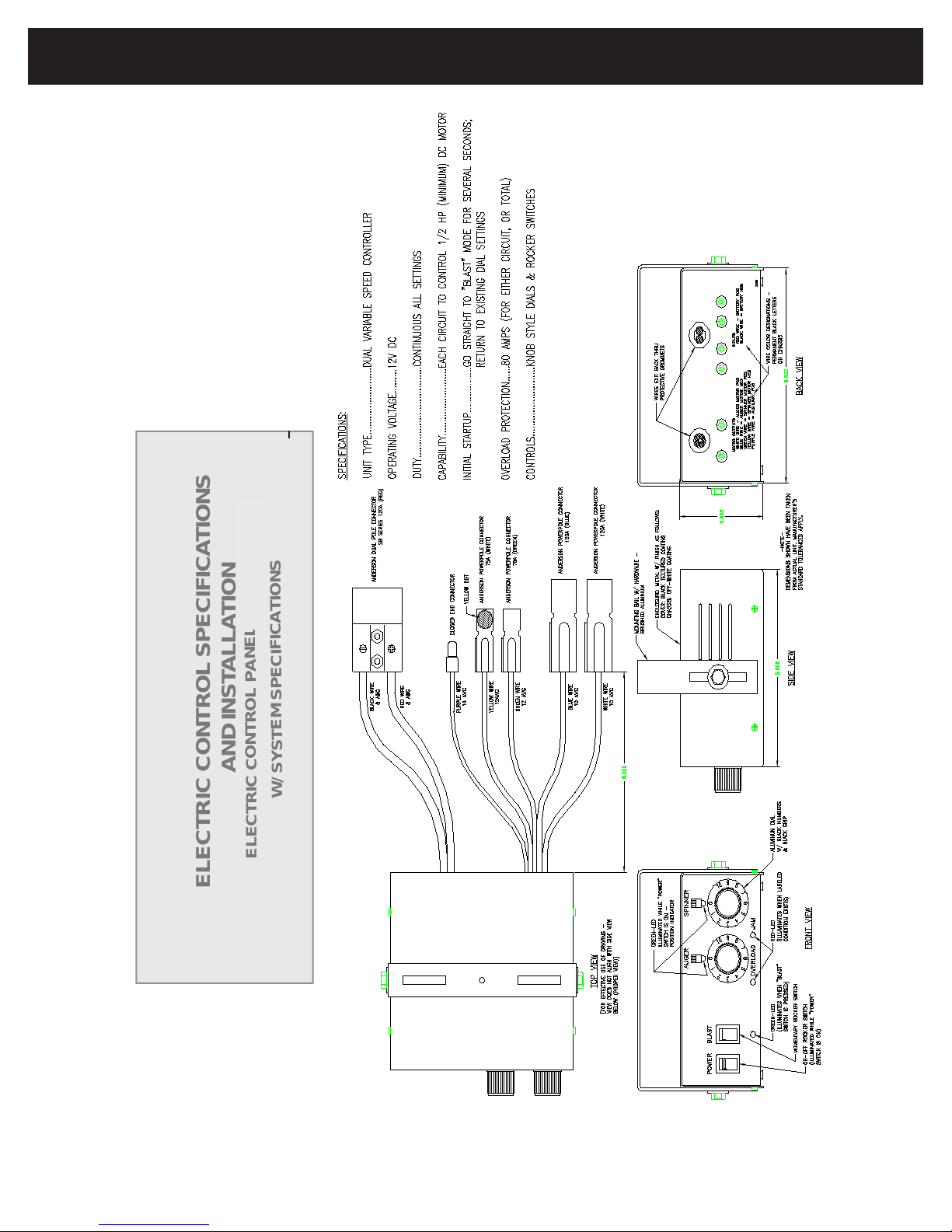
ELECTRIC CONTROL SPECIFICATIONS
W
/
S
Y
S
T
E
M
S
P
E
CIF
I
CAT
I
O
NS
E
L
E
CTRI
C
CONTROL
P
ANEL
04623-008-00
63962
WWW.MEYERPRODUCTS.COM 00122-517-01 SEPTEMBER 2009
PAGE 6
Page 7
SEL INSTALLATION AND OPERATING INSTRUCTION MANUAL
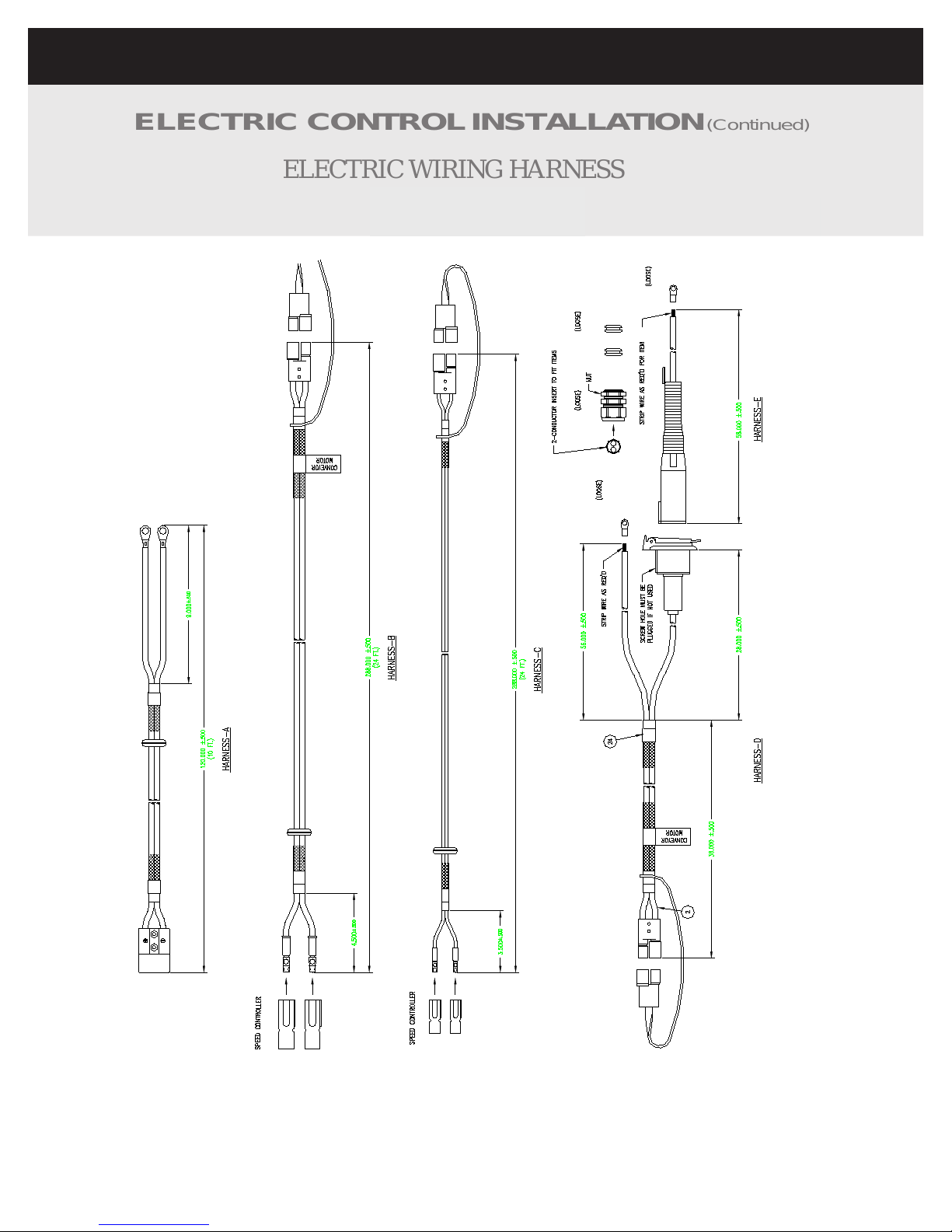
ELECTRIC WIRING HARNESS
04616-118-00
ELECTRIC CONTROLINSTALLATION
63963
(Continued)
WWW.MEYERPRODUCTS.COM 00122-517-01 SEPTEMBER 2009
PAGE 7
Page 8
SEL INSTALLATION AND OPERATING INSTRUCTION MANUAL
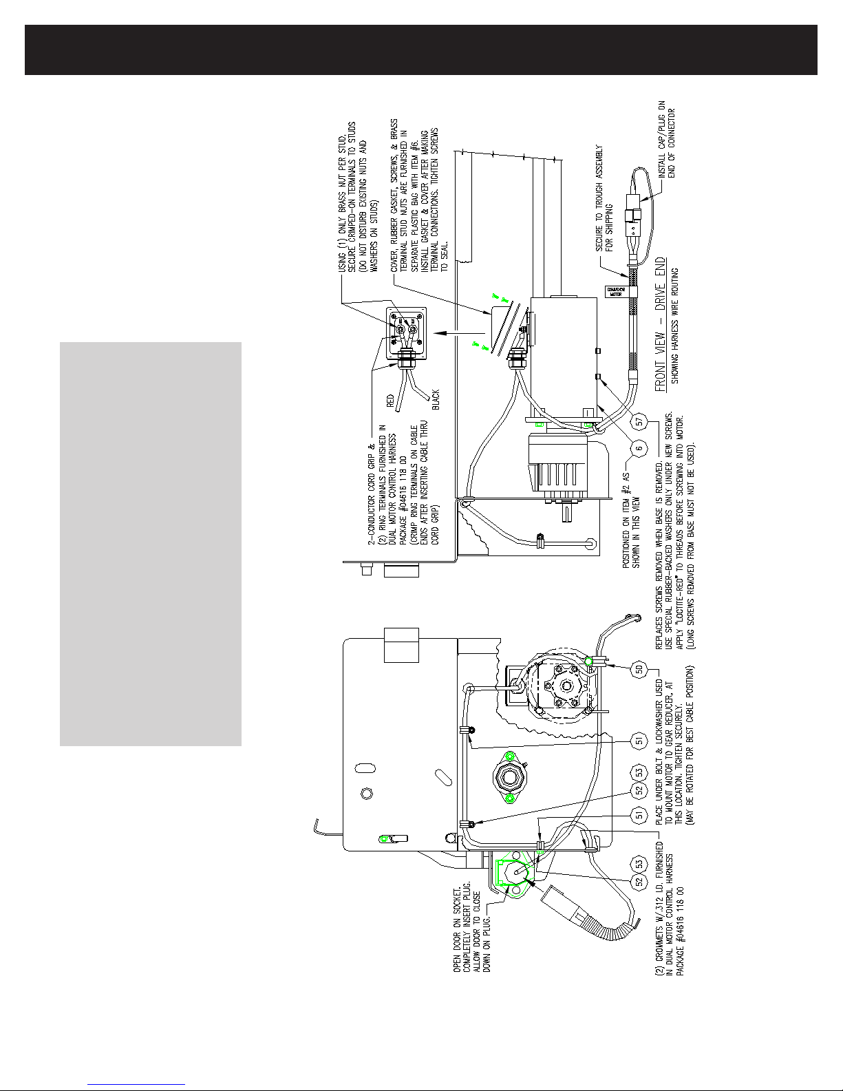
DRIVE END VIEW
64020 (SS TROUGH ASSY)
64019 (CS TROUGH ASSY)
64022 ( SS CD TROUGH ASSY)
64021 ( CS CD TROUGH ASSY)
WIRING HARNESS ROUTING
WWW.MEYERPRODUCTS.COM 00122-517-01 SEPTEMBER 2009
PAGE 8
Page 9

SEL INSTALLATION AND OPERATING INSTRUCTION MANUAL
PARTS LIST CONT’D
64019 (CS TROUGH ASSY)
64020 (SS TROUGH ASSY)
64021 (CS CD TROUGH ASSY)
64022 (SS CD TROUGH ASSY)
ITEM PRODUCT QTY DESCRIPTION
6 64015 1 MOTOR, 12 V 1650RPM 60A 1/2 HP
50 64023 1 CLAMP, CUSHIONED 3/4” WIDE 1/2”
51 63245 3 CLAMP, CUSHIONED 3/8” LOOP SS
52 CS 20003 3 BOLT, 1/4-20 X 3/4” HH G5 ZP
SS 62189 3 BOLT, 1/4-20 X 3/4” HH SS
53 CS 62187 3 NUT, 5/16-18 SER FLANGE ZP
SS 62690 3 NUT, 5/16-18 SER FLANGE SS
57 64024 4 SCREW, M6--1.0 X 10 SCH SS
WWW.MEYERPRODUCTS.COM 00122-517-01 SEPTEMBER 2009
PAGE 9
Page 10

SEL INSTALLATION AND OPERATING INSTRUCTION MANUAL
NOTES
WWW.MEYERPRODUCTS.COM 00122-517-01 SEPTEMBER 2009
PAGE 10
Page 11
SEL INSTALLATION AND OPERATING INSTRUCTION MANUAL
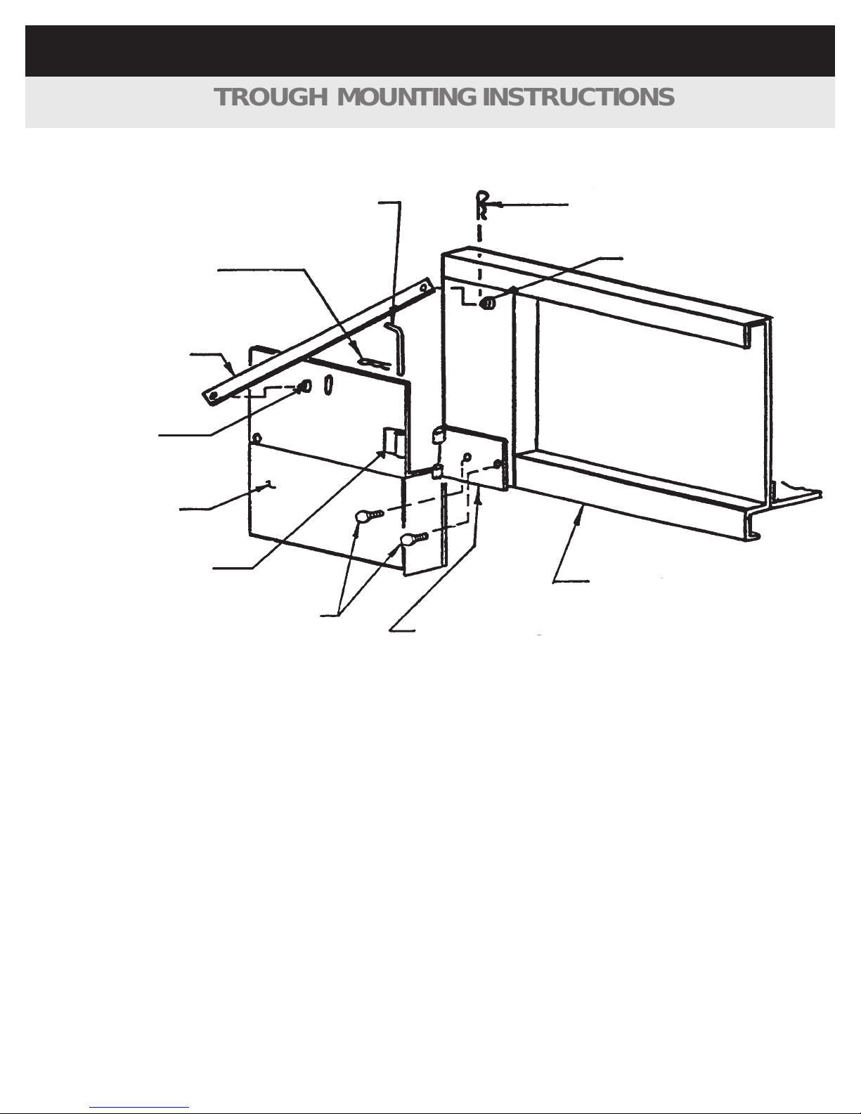
TROUGH MOUNTING INSTRUCTIONS
Hinge Pin
Hairpin Keeper (Large)
Hanger Iron Brace
Brace pin
Spreader
Detach Bracket
1/2” X 1 1/4”
Bolts
Quick Detach Plate
Truck Dump Body
Brace pin
Hairpin Keeper (Large)
WWW.MEYERPRODUCTS.COM 00122-517-01 SEPTEMBER 2009
PAGE 11
Page 12

SEL INSTALLATION AND OPERATING INSTRUCTION MANUAL
TROUGH MOUNTING INSTRUCTIONS
(Continued)
GENERAL:
This spreader is designed to mount rigidly on the rear of the truck dump body, below the tailgate, and supported by brackets bolted to the rub rails of the dump body. Instructional drawing
Support spreader and other heavy components solidly when positioning for mounting on truck
dump body.
IMPORTANT:
On occasion, due to improper handling during shipmen
t or storage, the vertical ends of the
trough get bent in or out slightly. Be sure these are square and true before installation. Once
installed, the mounting brackets should prevent further deformation.
1. Position the spreader under the dump body tailgate with the auger drive housing to
the right side of the truck. The trough lip on the forward side of the spreader should
be as close as possible to t
he cross member under the floor of the dump body.
The tailgate of the dump body should lay down horizontally over the spreader, yet the
spreader must be mounted up under the tailgate as high as possible.
2. Pin quick detach plates to spreader detach brackets.
3. Position quick detach plates against dump body cornerposts and clamp in a level
position. Weld adequately to support loaded spreader trough. I
f bolting, is desired,
solidly.
4. Position hanger iron brace on brace pin located on spreader endplates.
5. Locate brace pins on dump body cornerposts approximately as shown using braces
for exact positioning. (Braces may require bending for proper fit.)
6. Weld brace pins solidly to dump body, and retain braces at each end with hairpin
keepers.
7. Carefully remove temporary spreader positioning apparatus
.
.
8. If there is a gap between the trough lip and the dump body rear cross member, a
“spillboard” of about 3/16” x 2” steel may be welded or bolted to the forward lip of the
spreader to form a seal under the dump body floor. It may have to be notched or cut
to fit around tailgate latches or other obstructions on the rear of the dump body.
DANGER
drill (2) holes for 1/2” bolts simultaneously through bracket, cornerpost and bolt
is included in this manual to show the details on page 11.
WWW.MEYERPRODUCTS.COM 00122-517-01 SEPTEMBER 2009
PAGE 12
Page 13

SEL INSTALLATION AND OPERATING INSTRUCTION MANUAL
SUPPORT SPINNER ASSEMBLY SOLIDLY WHEN
MOUNTING ON SPREADER.
SPINNER ASSEMBLY PROCEDURE:
engage threads in motor shaft a minimum of 3/8” when bolt is tight.
bolts and flange nuts.
a. Appropriate spinner height depends on truck frame ground clearance. A shorter
spinner height for light and medium duty trucks with contractor style bodies, a
taller spinner height for heavy duty trucks with full size dump bodies.
llar in middle notch of spinner extension mounting bracket, slide
spinn
er hinge rod through both the mounting bracket and lock collar.
MOUNTING PROCEDURES:
TRUCK SHOULD BE ON LEVEL SURFACE.
1. Install spinner assembly on spreader by sliding the hinge rod into the mounting tabs on
bottom door. Insert (2) keeper pins into hinge rod. Center and lock spinner assembly
between mounting tabs.
2. Raise and lower dump body to check spinner ground clearances. Adjust
spinner height if needed. Repeat step if adjustments are made.
DANGER
“SEL” SERIES SPREADERS
INSTALLATION OF SPINNER ASSEMBLY ON
1
. Attach spinner disc to hub with 5/16” x 1 1/2” bolts, flatwashers and flange nuts.
2
. Apply anti-seize compound to spinner motor shaft.
3
. Mount spinner disc/hub assembly on spinner motor shaft.
4
. Secure disc/hub assembly to motor shaft with proper size hardware (provided). Bolt should
5
. Attach spinner frame assembly to spinner extension mounting bracket with (4) 3/8” X 1”
6
. While holding lock co
7.Pin spinner cariage bracket to the trough and bottom door. Insert lynch pins
WWW.MEYERPRODUCTS.COM 00122-517-01 SEPTEMBER 2009
PAGE 13
Page 14

SEL INSTALLATION AND OPERATING INSTRUCTION MANUAL
EQUAL TO
X
Y
This diagram to used as refer-
ence only
Y
EQUAL TO
X
WWW.MEYERPRODUCTS.COM 00122-517-01 SEPTEMBER 2009
PAGE 14
Page 15

SEL INSTALLATION AND OPERATING INSTRUCTION MANUAL
WWW.MEYERPRODUCTS.COM 00122-517-01 SEPTEMBER 2009
PAGE 15
Page 16

SEL INSTALLATION AND OPERATING INSTRUCTION MANUAL
SpreadÊpatternÊadjustment,Êcont'd
WWW.MEYERPRODUCTS.COM 00122-517-01 SEPTEMBER 2009
PAGE 16
Page 17

SEL INSTALLATION AND OPERATING INSTRUCTION MANUAL
OPERATING INSTRUCTIONS
1. WHEN STARTING UP NEW EQUIPMENT, BE SURE EVERYONE IS STANDING CLEAR, WATCH
FOR ANYTHING THAT MAY REQUIRE SHUTTING SYSTEM DOWN. EQUIPMENT MUST BE
STARTED UP SLOWLY AND WATCHED FROM A SAFE DISTANCE. WATCH FOR ANYTHING THAT
MAY BE HITTING SOMETHING THAT IT SHOULD NOT BE HITTING, AND LISTEN FOR SOUNDS
THAT ARE ABNORMAL. CORRECT ANYTHING THAT IS ABNORMAL BEFORE CONTINUING USE
OF THE EQUIPMENT.
2. BEFORE INSTALLATION, MAINTENANCE, CLEANING, OR REMOVAL OF SPREADER, ALL
INITIAL START UP:
motor when disconnected. The spreader is shipped with the interlock device in the disconnected position and
must be connected for operating the spreader.
opened, and slower as knobs are closed.
DANGER
,
ELECTRICAL CONNECTIONS MUST BE DISCONNECTED
.
(Left hand mounted spinner should turn in CCW rotation
as viewed from above spinner.
,
Auger should turn in direction which makes
auger fliting appear to move towards trough dropout
opening.)
1. Connect
electrical harnesses
to safety interlock, spreader and spinner.
2
. Keep auger and spinner knobs on
controller to zero
position.
3
.
Push power switch to
“ON” position.
4
. Examine auger and spinner to see if they are functioning properly. (They will be operating slowly.)
6
.
Open knobs to other positions and check to see if spinner and auger operate faster as knobs are adjusted.
7
. Shut
power switch to off
This spreader is equipped with a
elctrical
safety interlock device designed to interrupt
electrical
flow to the auger
5
.
Open control
knobs to other positions and check to see if spinner and auger operate faster as knobs are
WWW.MEYERPRODUCTS.COM 00122-517-01 SEPTEMBER 2009
PAGE 17
Page 18

SEL INSTALLATION AND OPERATING INSTRUCTION MANUAL
OPERATING SPREADER:
OPERATING INSTRUCTIONS
(Continued)
PREPARING SPREADER FOR USE:
1. Position spreader cover plate vertically and secure with latches.
2. With dump body empty, unlatch dump body tailgate from bottom and open as wide as possible
but not bearing against cover plate, set the stop (or spread) chains.
3. Loosen spinner lock and slide spinner assembly to far left and retighten lock. (Position
for spreading three or four lane highway from right lane.)
4. Put spreading material in dump body and raise dump body to fill spreader trough.
5. Lower dump body to safe position.
6. Press controller power switch to “ON” position. Spread small amount of
material to determine placement of material at various spinner and auger speeds with spinner in this far left
position.
7. Press controller switch to “OFF” position and shut off truck engine.
8. Loosen spinner lock and slide spinner assembly to far right and retighten lock. (Position for
spreading behind truck and to extreme right covering up to four lanes from left lane.)
9. Start truck engine
.
10. Press controller switch to “ON” position. Spread small amount of material to determine
placement of material at various spinner and auger speeds with spinner in this
far right position
.
11. It should now be visible that various spread patterns may be obtained by placing spinner at various
positions from left to right, and by changing spinner speeds on valve.
1. For operating electrical system, follow same procedures as for preparing spreader for use.
2. Any speed knob setting changes may be made while truck is in motion.
3. Spinner and auger may be stopped at the same time, without changing their valve settings, by
pressing power switch to “OFF” position.
4. For normal use of dump truck, cover plate may be laid flat over spreader trough and locked in place
.
Dump body tailgate may be opened from top or bottom.
5. When using truck for normal hauling and dumping, it is recommended that electrical safety interlock be
disconnected. Push dust cap onto disconnect.
6. Refer to safety interlock danger decal on trough cover plate for proper use of safety interlock.
7. To avoid spinner damage, spinner may be removed when truck is used for extensive hauling. Protect
electric disconnects with appropriate plugs and caps.
WWW.MEYERPRODUCTS.COM 00122-517-01 SEPTEMBER 2009
PAGE 18
Page 19

SEL INSTALLATION AND OPERATING INSTRUCTION MANUAL
RECOMMENDED REGULAR MAINTENANCE
DANGER
SERIOUS PERSONAL INJURY CAN RESULT FROM BEING CAUGHT IN A TURNING AUGER, A TURNING
SPINNER, OR OTHER OPERATING TRUCK EQUIPMENT. BEFORE PERFORMING MAINTENANCE
OPERATIONS, PARK VEHICLE ON LEVEL GROUND. SET PARKING BRAKE, SHUT OFF ALL POWER,
AND SHUT OFF TRUCK ENGINE. ALWAYS REPLACE SHIELDS AND COVERS WHEN MAINTENANCE IS
COMPLETE.
1. Clean electricalÊplugs before taking apart or connecting.
2. Protect electricalÊplugs while in use and after taking apart with dustÊcaps
or other suitable protection.
3
. Auger bearing requires periodic greasing every 15 hours of use and more
frequent greasing during periods of greater use.
4. Greasing spinner hinge rod at support pivot points is suggested.
5. Hosing down and cleaning spreader after each use, and repainting or oiling after
each season will greatly prolong spreader life. To open bottom door and top cover,
disconnect
electrical safety interlock and pivot around to end of spreader.
6. Spreader trough should be completely emptied after each use during severe cold
weather to prevent material from freezing around auger.
WWW.MEYERPRODUCTS.COM 00122-517-01 SEPTEMBER 2009
PAGE 19
Page 20

SEL INSTALLATION AND OPERATING INSTRUCTION MANUAL
PARTS LISTING
WWW.MEYERPRODUCTS.COM 00122-517-01 SEPTEMBER 2009
PAGE 20
Page 21

ER
SEL INSTALLATION AND OPERATING INSTRUCTION MANUAL
)
)
)
)
D TROUGH ASSY
D TROUGH ASSY
TROUGH ASSY
TROUGH ASSY
64019 (CS
AND HOLD DOWN CLIPS
64020 (SS
64022 (SS C
64021 (CS C
TOP VIEW SHOWN WITHOUT TOP COV
WWW.MEYERPRODUCTS.COM 00122-517-01 SEPTEMBER 2009
PAGE 21
Page 22

SEL INSTALLATION AND OPERATING INSTRUCTION MANUAL
PARTS LIST
64019 (CS TROUGH ASSY)
64020 (SS TROUGH ASSY)
64021 (CS CD TROUGH ASSY)
64022 (SS CD TROUGH ASSY)
ITEM PART NUMBER QTY DESCRIPTION
1 CS 64025 1 WELD, TROUGH, 10G CS
CS C/D 64026 1 WELD, TROUGH, 10 GA CS CENTER DROP
SS 64027 1 WELD, TROUGH 10 G S2
SS C/D 64028 1 WELD, TROUGH, 10 GA S2 CENTER DROP
2 64029 1 REDUCER, GEAR 29.4:1
3 64030 4 BOLT, M10-1.5 X 20 SCH SS
5 63993 5 SCREW, M8-1.25 X 20 SCH SS
6 64015 1 MOTOR, 12 V 1650 RPM 60 A 1/2 HP
8 62480 1 WASHER, FELT 1 1/4” ID X 2 1/2” OD
9 63051 1 WELD, AUGER, SA (2 1/2” TUBE)
64031 1
12 CS 62611 9
SS 62743 9
13 64032 1 SPROCKET, 50BL21-1 1/4” BORE
14 64033 1 SPROCKET, 50BL16-3/4” BORE
16 64034 1 BUSHING, TENSIONER STANDOFF S3
17 CS 20051 1 BOLT, 3/8-16 X 1 1/2” HH G5 ZP
SS 64035 1 BOLT, 3/8-16 1 1/2” HH SS
18 CS 64037 1 PLATE, WHEEL TENSIONER 10G CS
SS 64037 1 PLATE, WHEEL TENSIONER 10G S2
20 64038 1 BOLT, SHOULDER 1/2 X 1 1/2” HH
21 64039 1 ROLLER, THNSIONER UHMW
23 CS 64040 1 COVER, CHAIN 10G CS
SS 64041 1 COVER, CHAIN 10G S2
24 CS 63994 3
SS
36 CS 64042 1 COVER, ANTI-FLOW 10G CS
SS 64043 1 COVER, ANTI-FLOW 10G S2
37 CS 61233 2 KEEPER, HAIRPIN LARGE
SS 63193 2 KEEPER, HAIRPIN LARGE SS
48 60421 1 KEY, 1/4: SQ. X 1 1/4”
56 CS 64044 1 FLATWASHER, 3/8” U.S.S. ZP
SS 63565 1 FLATWASHER, 3/8” U.S.S. SS
57 64024 4 SCREW, M6-1.0 X 10 SCH SS
62746
3
WELD, AUGER, SA (2 1/2” TUBE) CENTER DROP
NUT, 3/8-16 SER FLANGE ZP
NUT, 3/8-16 SER FLANGE SS
BOLT, 3/8-16 X 3/4” CA G5 ZP
BOLT, 3/8-16 X 3/4” CA SS
WWW.MEYERPRODUCTS.COM 00122-517-01 SEPTEMBER 2009
PAGE 22
Page 23

SEL INSTALLATION AND OPERATING INSTRUCTION MANUAL
IF DEFACED - ORDER PART NO. 04049 411 00
TOP COVER
(OPENED)
BOTTOM DOOR
ELECTRICAL COUPLING NOT CONNECTED
LATCH HANDLE CAN BE OPENED
AND BOTTOM DOOR CAN BE OPENED
TOP COVER CAN BE OPENED REARWARD
SPREADER WILL NOT OPERATE
ORIGINAL INTENT AS SHOWN
IS ALTERED IN ANY WAY FROM ITS ORIGINAL INTENT AS SHOWN
IS NOT MAINTAINED SO AS TO OPERATE ACCORDING TO ITS
SERIOUS PERSONAL INJURY OR DEATH CAN RESULT
TOP COVER
IF THE SAFETY INTERLOCK DEVICE - AS INSTALLED ON THIS SPREADER:
(CLOSED)
SPREADER WILL OPERATE
ELECTRICAL COUPLING CONNECTED
EXPOSING AUGER
AND BOTTOM DOOR CANNOT BE OPENED
LATCH HANDLE IS FULLY CLOSED
TOP COVER CANNOT BE OPENED REARWARD
BOTTOM DOOR
IF DEFACED - ORDER PART NO. 04049 121 00
DANGER
REAR VIEW
64019 (CS TROUGH ASSY)
64020 (SS TROUGH ASSY)
64022 (SS CD TROUGH ASSY)
64021 (CS CD TROUGH ASSY)
IF DEFACED - ORDER PART NO. 04049 044 00
DANGER
Stay clear while
spinner is turning
WWW.MEYERPRODUCTS.COM 00122-517-01 SEPTEMBER 2009
PAGE 23
Page 24

SEL INSTALLATION AND OPERATING INSTRUCTION MANUAL
PARTS LIST CONT’D
64019 (CS TROUGH ASSY)
64020 (SS TROUGH ASSY)
64021 (CS CD TROUGH ASSY)
64022 (SS CD TROUGH ASSY)
ITEM PART NUMBER QTY. DESCRIPTIONS
7 CS 20049 4 BOLT, 3/8-16 X 1 HH G5 ZP
SS 62697 4 BOLT, 3/8-16 X 1 HH SS
12 CS 62611 9 NUT, 3/8-16 SER FLANGE ZP
SS 62743 9 NUT, 3/8-16 SER FLANGE SS
17 CS 20051 1 BOLT, 3/8-16 X 1 1/5” HH G5 ZP
SS 64035 1 BOLT, 3/8-16 X 1 1/2” HH SS
19 CS 20305 8 LOCKNUT, 3/8-16 Nl ZP
SS 63348 8 LOCKNUT, 3/8-16 Nl SS
24 CS 63994 3 BOLT, 3/8-16 X 3/4” CA G5 ZP
SS 62746 3 BOLT, 3/8-16 X 3/4” CA SS
25 CS 64045 1 WELD, BOTTOM DOOR 10 G CS
CS C/D 64046 1 WELD, BOTTOM DOOR, 10G CD CENTER DROP
SS 64047 1 WELD, BOTTOM DOOR 10G SS
SS C/D 64048 1 WELD, BOTTOM DOOR10G SS CENTER DROP
26 64003 2 LATCH, BOTTOM DOOR CS
64004 2 LATCH, BOTTOM DOOR S3
27 CS 63279 2 LOCKNUT, 5/8-11 TOP LOCK ZP
SS 63425 2 LOCKNUT, 5/8-11 TOP LOCK SS
28 CS 20068 2 BOLT, 3/8-16 X 2 1/2” HH G5 ZP
SS 63198 2 BOLT, 3/8-16 X 2 1/2” HH SS
29 CS 64049 1 WELD, TOP COVER 10G CS
SS 64050 1 WELD, TOP COVER 10G S2
30 CS 64051 1 CLIP, HOLD-DOWN 10 G CS
SS 64052 1 CLIP, HOLD-DOWN 10 G S2
31 CS 64053 1 HANDLE, LIFT CS
SS 64054 1 HANDLE, LIFT S3
32 63280 2 BRACKET, S2
33 63283 4 BOLT, 5/16-18 X 5/8” CA SS
34 63310 4 NUT, 5/16-18 SER FLANGE SS
35 CS 62443 2 FORMING, HANDLE, ZP
SS 62731 2 HANDLE, SS
39 62515 1 DECAL, DANGER (AUGER)
40 62006 1 DECAL, DANGER (SPINNER)
42 64018 1 DECAL, SAFETY INTERLOCK ELECTRIC
54 CS 63305 2 BOLT, 5/16-18 X 3/4” CA G5 ZP
SS 62640 2 BOLT, 5/16-18 X 3/4’ CA SS
55 63304 2 NUT, 5/16-18 X 3/4” CA G5 ZP
63310 2 NUT, 5/16-18 X 3/4’ CA SS
WWW.MEYERPRODUCTS.COM 00122-517-01 SEPTEMBER 2009
PAGE 24
Page 25

SEL INSTALLATION AND OPERATING INSTRUCTION MANUAL
CROSS SECTIONAL VIEW
END PLATE VIEW
(REAR VIEW SECTION A-A)
64019 (CS TROUGH ASSY)
64020 (SS TROUGH ASSY)
64022 (SS CD TROUGH ASSY)
64021 (CS CD TROUGH ASSY)
WWW.MEYERPRODUCTS.COM 00122-517-01 SEPTEMBER 2009
PAGE 25
Page 26

SEL INSTALLATION AND OPERATING INSTRUCTION MANUAL
PARTS LIST CONT’D
64019 (CS TROUGH ASSY)
64020 (SS TROUGH ASSY)
64021 (CS CD TROUGH ASSY)
64022 (SS CD TROUGH ASSY)
ITEM PART NUMBER QTY DESCRIPTION
10 61163 2 BEARING, 1 1/4”
11 CS 20066 4 BOLT, 3/8-16 Z 1 1/4” HH G5 ZP
SS 62695 4 BOLT, 3/8-16 X 1 1/4” HH SS
12 CS 62611 9 NUT, 3/8-16 SER FLANGE ZP
SS 62743 9 NUT, 3/8-16 SER FLANGE SS
19 CS 20305 8 LOCKNUT, 3/8-16 Nl ZP
SS 62638 8 LOCKNUT, 3/8-16 Nl SS
24 CS 63994 3 BOLT, 3/8-16 X 3/4” CA G5 ZP
SS 62746 3 BOLT, 3/8-16 X 3/4” CA SS
29 CS 64049 1 WELD, TOP COVER 10G CS
SS 64050 1 WELD, TOP COVER 10G S2
30 CS 64051 1 CLIP, HOLD-DOWN 10 G CS
SS 64052 1 CLIP, HOLD-DOWN 10 G S2
31 CS 64053 1 HANDLE, LIFT CS
SS 64052 1 HANDLE, LIFT S3
32 63280 2 BRACKET, S2
33 63283 4 BOLT, 5/16-18 X 5/8” CA SS
34 63310 4 NUT, 5/16-18 SER FLANGE SS
35 CS 62443 2 FORMING, HANDLE, ZP
SS 62731 2 HANDLE, SS
36 CS 64042 1 COVER, ANTI-FLOW 10 G CS
SS 64043 1 COVER, ANTI-FLOW 10G S2
WWW.MEYERPRODUCTS.COM 00122-517-01 SEPTEMBER 2009
PAGE 26
Page 27

SEL INSTALLATION AND OPERATING INSTRUCTION MANUAL
DRIVE END VIEW
64019 (CS TROUGH ASSY)
64020 (SS TROUGH ASSY)
64021 (CS CD TROUGH ASSY)
64022 (SS CD TROUGH ASSY)
127 Walnut Street
R
Lindenwood, IL 61049
(888) 825-7323
May be covered by one or more of these patents:
5669531 0
3851804
3332691
3189355
3510066
Description:
Serial Number:
P, TA, S - -, S3, - - - - - -
0103-1323
00119-651-01
Part Number:
1. KEEP ALL SHIELDS IN PLACE.
2. MAKE CERTAIN EVER YONE IS CLEAR BEFORE
STARTING MACHINE OR MOVING VEHICLE.
3. KEEP HANDS, FEET, A ND CLOTHING AWAY FROM
ALL POWER DRIVEN PARTS.
4. DISENGAGE PTO, SHUT OFF HYDRAULIC VALVE,
AND SET PARKING BRAKE BEFORE LEAVING
OPERATORS POSITI ON. MAKE SURE ALL MOVEMENT
HAS STOPPED BEFOR E SERVICING, UNCLOGGING,
OR CLEANING MACHINE.
5. USE FLASHING LIGH TS WHEN OPERATING MACHINE.
6. MAKE SURE MACHIN E IS SOLIDLY SUPPORTED
WHEN IT IS BEING MOUNTED, DISMOUNTED,
OR STORED.
IF DEFACED - ORDER PART NO. 04049 045 00
WWW.MEYERPRODUCTS.COM 00122-517-01 SEPTEMBER 2009
PAGE 27
Page 28

SEL INSTALLATION AND OPERATING INSTRUCTION MANUAL
PARTS LIST CONT’D
64019 (CS TROUGH ASSY)
64020 (SS TROUGH ASSY)
64021 (CS CD TROUGH ASSY)
64022 (SS CD TROUGH ASSY)
ITEM PRODUCT QTY DESCRIPTION
2
3
5
6
8
64029
64030
63993
64015
62480
1
4
5
1
1
10 61163 2 BEARING, 1 1/4”
11 CS 20066 4 BOLT, 3/8-16 Z 1 1/4” HH G5 Z
SS 62695 4 BOLT, 3/8-16 X 1 1/4” HH SS
12 CS 62611 9 NUT, 3/8-16 SER FLANGE ZP
SS 62743 9 NUT, 3/8-16 SER FLANGE SS
13
14
64032
64033
1
1
15 64056 1 CHAIN, ROLLER #50-48 PITCH W/C
16
64034
1
17 CS 20051 1 BOLT, 3/8-16 X 1 1/5” HH G5 ZP
SS 64035 1 BOLT, 3/8-16 X 1 1/2” HH SS
18 CS
SS
20
21
64036
64037
64038
64039
1
1
1
1
22 64057 1 SPRING, EXTENSION 6”
23 CS
SS
64040
64041
1
1
24 CS 63994 3 BOLT, 3/8-16 X 3/4” CA G5 ZP
SS 62746 3 BOLT, 3/8-16 X 3/4” CA SS
41 62007 1 DECAL, CAUTION
48
56 CS
SS
60421
64035
63565
1
1
1
REDUCER, GEAR 29.4:1
BOLT, M10-1.5 X 20 SCH SS
SCREW, M8-1.25 X 20 SCH SS
MOTOR, 12 V 1650 RPM 60 A 1/2 HP
WASHER, FELT 1 1/4” ID X 2 1/2” OD
SPROCKET, 50BL21-1 1/4” BORE
SPROCKET, 50BL16-3/4” BORE
BUSHING, TENSIONER STANDOFF S3
PLATE, WHEEL TENSIONER 10G CS
PLATE, WHEEL TENSIONER 10G S2
BOLT, SHOULDER 1/2 X 1 1/2” HH
ROLLER, TENSIONER UHMW
COVER, CHAIN 10G CS
COVER, CHAIN 10G S2
KEY, 1/4: SQ. X 1 1/4”
FLAT WASHER, 3/8” U.S.S. ZP
FLAT WASHER, 3/8” U.S.S. SS
WWW.MEYERPRODUCTS.COM 00122-517-01 SEPTEMBER 2009
PAGE 28
Page 29

SEL INSTALLATION AND OPERATING INSTRUCTION MANUAL
Assembled Spinner Image
1
2
7
5
4
6
10
6
11
9 12
8
13 14
WWW.MEYERPRODUCTS.COM 00122-517-01 SEPTEMBER 2009
PAGE 29
Page 30

SEL INSTALLATION AND OPERATING INSTRUCTION MANUAL
Assembled Spinner Image
Parts Listing
ITEM PRODUCT QTY DESCRIPTION
1 63271 2 ROD, HINGE, S3
2 22083 4 PIN, LYNCH
NS 63447 1 ROD, CARRIAGE SUPPORT S3
4 62769 1 COLLAR, SET 1”
5 62459 1 LOCK, SPINNER, S3
6 CS 64009 1 WELD, SPINNER FRAME 10G CS
SS 64010 1 WELD, SPINNER FRAME 10G SS
7 CS 64011 1 WELD, SPINNER CARRIAGE, 10 G CS
SS 64012 1 WELD, SPINNER CARRIAGE, 10G SS
8 64013 1 DISC, POY 18” 1.62 BORE CCW
9 CS 64014 1 WELD, SPINNER HUB CS
10 34102 1 MOTOR, 12V 1650rpm 60A 1/2 HP
11 64016 1 BOLT, M6-1.0 X 40 mm HH SS
12 64017 1 LOCKNUT M6-1.0 TOP LOCK SS
13 63268 4 BOLT, 5/16 - 18 X 1 1/4” HH SS
14 62743 5 NUT, 5/16 SER FLANGE SS
NS 62695 4 BOLT, 3/8-16 X 1 1/4” HH SS
NS 22230 4 FLATWASHER, 3/8” U.S.S. SS
NS 62743 4 NUT, 3/8-16 SER FLANGE SS
WWW.MEYERPRODUCTS.COM 00122-517-01 SEPTEMBER 2009
PAGE 30
Page 31

SEL INSTALLATION AND OPERATING INSTRUCTION MANUAL
CARRIAGE MOUNTING EXPLODED VIEW
2
1
6
1
3
10
17
16
18
7
8
19
14
15
4
5
13
12
9
11
WWW.MEYERPRODUCTS.COM 00122-517-01 SEPTEMBER 2009
PAGE 31
Page 32

SEL INSTALLATION AND OPERATING INSTRUCTION MANUAL
FRONT MOUNTED SPINNER CARRIAGE
ASSEMBLY PARTS LIST
ITEM PRODUCT QTY DESCRIPTION
1 63271 2 ROD, HINGE, S3
2 22083 4 PIN, LYNCH
3 63447 1 ROD, CARRIAGE SUPPORT S3
4 62769 1 COLLAR, SET 1”
5 CS 64009 1 WELD, SPINNER FRAME 10G CS
SS 64010 1 WELD, SPINNER FRAME 10G SS
6 CS 64011 1 WELD, SPINNER CARRIAGE, 10 G CS
SS 64012 1 WELD, SPINNER CARRIAGE, 10G SS
7 64013 1 DISC, POY 18” 1.62 BORE CCW
8 CS 64014 1 WELD, SPINNER HUB CS
9 34102 1 MOTOR, 12V 1/2 HP
10 63193 1 KEEPER, HAIRPIN LARGE, SS
11 62695 4 BOLT, 3/8-16 X 1 1/4” HH SS
12 22230 4 FLAT WASHER, 3/8” U.S.S. SS
13 62743 4 NUT, 3/8-16 SER FLANGE SS
14 63268 4 BOLT 5/16-18 X 1/1/4” HH SS
15 63173 5 FLATWASHER 5/16 U.S.S. SS
16 63310 5 NUT 5/16-18 SER FLANGE SS
17 64016 1 BOLT, M6-1.0 X 40 mm HH SS
18 64017 1 LOCKNUT, M6-1.0 TOP LOCK SS
19 62459 1 LOCK, SPINNER, S3
NS 62273 1 BOLT 5/16-18 1 1/2” HH SS
WWW.MEYERPRODUCTS.COM 00122-517-01 SEPTEMBER 2009
PAGE 32
Page 33

SEL INSTALLATION AND OPERATING INSTRUCTION MANUAL
CALL YOUR AUTHORIZED MEYER PRODUCTS DEALER FOR PARTS AND SERVICE
MEYER PRODUCTS (216) 486-1313
FAX (216) 486-9775
email: warranty@meyerproducts.com
NOTICE: INSTRUCTIONAL MATERIAL AND PARTS LISTS INCLUDED IN THIS MANUAL
ARE SUBJECT TO CHANGE WITHOUT NOTICE.
NAME PLATE INFORMATION
•
When ordering parts or requesting information or assistance, always include
the information listed below.
•
The Model Number and Serial Number for the Spreader are shown on the name
plate.
•
The space below is provided as a convenient place to record these numbers;
just fill in the blanks.
MODEL NUMBER________________________________
SERIAL NUMBER________________________________
DATE PURCHASED_______________________________
DEALER PURCHASED FROM______________________
DEALER’S SERVICE DEPARTMENT PHONE NUMBER
18513 Euclid Ave.
Cleveland, OH 44112
(216) 486-1313
Part Number: XXXXX
Description: P, SJDS - MEYER SPREDER
XXXXXX
May be covered by one or more of these patents:
Serial Number: XXXXX
WWW.MEYERPRODUCTS.COM 00122-517-01 SEPTEMBER 2009
PAGE 33
Page 34

SEL INSTALLATION AND OPERATING INSTRUCTION MANUAL
t
SPREADER ONE YEAR WARRANTY
Meyer Products (“Meyer”) warrants to the original purchaser only that it will repair, or, at the sole option of Meyer,
replace any part of the new Meyer covered product which proves to be defective in workmanship or material
under normal use for a period of one year from the date of delivery to the original purchaser. This warranty is no
transferable or assignable. The original purchaser’s sole and exclusive remedy against Meyer and Meyer’s sole
obligation for any and all claims, whether for breach of contract, warranty, tort (including negligence) or otherwise
shall be limited to providing, through its Distributor/Sub Distributor network, all labor and or parts necessary to
correct such defects free of charge. Any cost incurred in returning the product to the Distributor/Sub-Distributor is
the responsibility of the original purchaser.
The gasoline engine used in this product is covered by its own warranty as provided by the engine manufacturer.
A copy of this warranty is included with the engine.
EXCLUSIONS
THIS WARRANTY DOES NOT COVER PAINT, EXCEPT EXPENDABLE PARTS SUCH AS PINS, SPREADER FINS,
AND OTHER NORMAL WEAR ITEMS. MEY ER SHALL NOT BE LIABLE FOR ANY SPECIAL, INDIRECT OR
CONSEQUENTIAL DAMAGES ARISING FROM ANY CLAIMS ARISING HEREUNDER, OR FOR DAMAGES
RESULTING FROM LACK OF NECESSARY MAINTENANCE, OR FROM MISUSE, ACTS OF GOD, ALTERATION
OF A MEYER PLOW, SPREADER OR PART, OR FROM USE OF PARTS OR HYDRAULIC FLUID NOT SUPPLIED
BY MEYER. USE OF THE MEYER SNOWPLOW, SPREADER FOR ANY PURPOSE OTHER THAN PLOWING
SNOW OR SPREADING APPROVED MATERIAL ARE EXAMPLES OF AN ABUSE AND MISUSE.
THE FOREGOING WARRANTY IS EXCLUSIVE AND IN LIEU OF ALL OTHER WARRANTIES, EXPRESS OR
IMPLIED, INCLUDING, BUT NOT LIMITED TO, ANY IMPLIED WARRANTY OF MERCHANTABILITY OR FITNESS
FOR A PARTICULAR PURPOSE.
WARRANTY SERVICE
In order to obtain service under this warranty, the original purchaser must return the Meyer claimed defective
product to the Distributor/Sub-Distributor from whom the product was purchased or to any authorized Meyer
Distributor/Sub-Distributor, transportation and freight charges prepaid. Only Meyer Distributor/Sub-Distributors
are authorized to perform the obligations under these warranties.
GENERAL
It is the responsibility of the original purchaser to establish the warranty period by verifying the original delivery
date. A bill of sale, cancelled check or some other appropriate payment record may be kept for that purpose. It
is recommended, but not required, that the consumer verify the original delivery date by immediately returning the
attached Warranty Registration Card. No person is authorized to change this warranty or to create any warranty
other than that set forth herein. This warranty gives you specific legal rights and you may also have other rights
which vary from state to state.
Meyer Products
18513 Euclid Avenue
Cleveland, Ohio 44112
Phone (216) 486-1313
Fax (216) 486-3073
E-Mail advertising@meyerproducts.com
WWW.MEYERPRODUCTS.COM 00122-517-01 SEPTEMBER 2009
PAGE 34
Page 35

SEL INSTALLATION AND OPERATING INSTRUCTION MANUAL
NOTES
WWW.MEYERPRODUCTS.COM 00122-517-01 SEPTEMBER 2009
PAGE 35
Page 36

SEL INSTALLATION AND OPERATING INSTRUCTION MANUAL
MEYER PRODUCTS, LLC
18513 EUCLID AVE.
CLEVELAND, OHIO 44112-1084
PHONE: (216) 486-1313
FAX: (216) 486-9775
email:warranty@meyerproducts.com
website: www.meyerproducts.com
IMPORTANT
INFORMATION
ENCLOSED
36
WWW.MEYERPRODUCTS.COM 00122-517-01 SEPTEMBER 2009
PAGE 36
 Loading...