

Page 1
Meyer Sound Laboratories, Inc.
2832 San Pablo Avenue
Berkeley, CA 94702
Operating Instructions
M-1A
Control
Electronics
Unit
The Meyer Sound M-1A is
an active signal processor
designed for use with Meyer
Sound UPA-1C and UM-1C
loudspeakers. lt is a single
channel device, and it
occupies a single 13⁄4-inch
rack space. The functions
of the M-1A are:
■ Active crossover for biamplication
■ Loudspeaker frequency
response and phase
response alignment
■ SpeakerSense™ driver
protection
+–
Input
Sub
In
Lo Hi
Sense
Lo
Out
Hi
Out
1/4 A
Hi Channel
+–
Lo Channel
Amplifier
Loudspeaker Cable
Input
1 Meter
Pigtail
Adapter
Red
Sense
Cable
Red
Black
Sense
Cable
Black
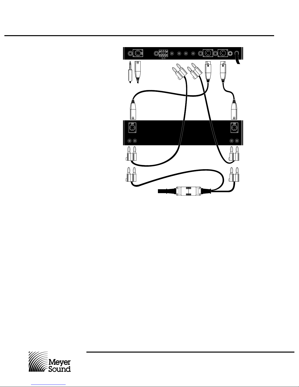
Connections
The M-1A operates at line level and is designed to be the last component in the chain
before the power amplier. Connections to
the M-1A should be made according to the
diagram above.
1. Signal inputs to the M-1A may be either
balanced or unbalanced. For best signal-to-noise ratio, the average input level
should be at least 1 volt RMS. The M-1A
will accept peak inputs of up to +26 dBv
balanced, or +20 dBv unbalanced.
2. The Sub input is used only when the M1A is operated in conjunction with Meyer
Sound B-2, B-2A or B-2AEX subwoofer
Controllers.
3. SpeakerSense™ connections are made
from the output of the power amplier
back to the M-1A Sense inputs. The Hi
output of the power amplier must be
connected to the Hi Sense input, and the
Lo output of the power amplier to the Lo
Sense input in order for the SpeakerSense
driver protection circuitry to operate properly.
Note. Polarity of these connections does not
matter.
4. Signal outputs from the M-1A may be
either balanced or unbalanced. The maximum output levels before clipping are
+26 dBv balanced, +20 dBv unbalanced.
5. Connections between the power amplier
outputs and the Meyer Sound loudspeaker
used with the M-1A should be made according to the instructions for the particular
loudspeaker (UPA-1C or UM-1C). These
connections must be veried for correct
polarity, and correct channel assignment
(Hi to Hi, Lo to Lo). Color codes given
in the diagram are those used for Meyer
Sound cables and adapters.
Note. The grounding strap on the M-1A rear
panel connects circuit ground (signal common) to earth ground (U-ground). Lifting this
strap from the terminal block disconnects
circuit ground from earth ground (the chassis remains connected to U-ground). If hum
problems occur, this feature may be used to
control ground loops in the system.
Page 2
Operating Instructions
Meyer Sound Laboratories, Inc.
2832 San Pablo Avenue
Berkeley, CA 94702
M-1A
Control
Electronics
Unit
Meyer Sound Laboratories, Inc.
2832 San Pablo Avenue
Berkeley, CA 94702
Operating Instructions
M-1A
Control
Electronics
Unit
Once all the connections have been made
and veried, the system is ready to operate.
■ The M-1A Level control should be set at
minimum.
■ Switch on AC to the M-1A rst, then to the
power amplier.
■ Set the power amplier level controls (if
any) to maximum.
■ Advance the M-1A Level control to set the
system sensitivity. If the system is not operating properly, recheck all connections.
Operation
Preset Panel Controls
The setup controls on the M-1A Preset Panel
are designed to be used to tailor the system
response for particular applications. Remove
the Preset Panel cover plate to adjust the
controls.
Safe Switch. The M-1A incorporates three
limiters in the SpeakerSense driver protection circuitry (see detailed description, below).
When the Safe switch is engaged, the RMS
limiters come on at 6 dB lower power levels, affording added protection when heavy
continuous power demands are placed on
the system. (The VHF peak limiter threshold
is unaffected.) For operator convenience, a
green LED indicator is provided on the M-1A
front panel and when the Safe switch is engaged, this indicator will light. Note: It is recommended that the Safe switch be engaged
until the operator is familiar with the system’s
capabilities.
VHF Switch and Control. The VHF Switch
affects the very high frequency response of
the system. It selects either a preset (CAL)
high frequency response or variable response
(VAR). In the VAR position, system response
around 16 kHz is adjustable (single-turn
screwdriver adjustment) from +6 dB to -4 dB
around the preset point (CCW for increased
level at 16 kHz). This feature may be used
to emphasize or de-emphasize sibilants,
compensate for room acoustics, etc. Note:
Because of the difference in high frequency
directivity patterns between the UPA-1C end
the UM-1C UltraMonitor, it is recommended
that the VHF switch be set in the CAL position
for the UM-1C UltraMonitor, and in the VAR
position — with the VAR control fully CCW
— for the UPA-1C.
Lo Cut Switch. This switch introduces a
6 dB/octave high pass lter at 160 Hz. It is
designed to provide an alternative crossover
slope when using Meyer Sound subwoofers,
but can also be used to compensate for the
proximity effect of cardioid microphones. This
lter is automatically inserted when the Sub
Input is used.
SpeakerSense™
Driver Protection
Through the Sense connections back to the
M-1A from the power ampliers, the SpeakerSense circuitry of the M-1A continuously
monitors the voltages across both high and
low frequency drivers. If the amplier output
exceeds the safe operating limits of the drivers, independent limiters are automatically
activated, holding down the level of the M1A’s outputs.
The operation of the SpeakerSense circuitry is
indicated by a set of ve LEDs located on the
front panel.
■ Sense Indicators. These function as sig-
nal presence indicators, and verify that the
Sense connections back to the M-1A are
made. These indicators will be lit whenever
a signal is present, or will icker at low
signal levels.
■ Limit Indicators. These indicators will
come on whenever the corresponding limiter is activated and a moderate amount of
ashing of these indicators is acceptable.
The HF and LF limiters have an attack
time of 100 msec, so they will not affect
peaks in the program material, nor will they
prevent momentary amplier clipping on
peaks.
Page 3

Meyer Sound Laboratories, Inc.
2832 San Pablo Avenue
Berkeley, CA 94702
Operating Instructions
M-1A
Control
Electronics
Unit
Verifying Limiter
Operation
To verify limiter operation in the eld:
■ Disconnect loudspeakers, leaving the
amplier and the M-1A in their standard
connection conguration.
■ If your amplier requires a load, use resistive loads sufcient to dissipate the full
power of the amplier.
■ Turn on both the M-1A and the amplier.
■ Set the VHF switch to CAL, the Lo Cut out
and the Safe switch in.
■ Supply an input to the M-1A, preferably a
sine wave oscillator. If you do not have an
oscillator, use a compact disc with dense
program material and a mixer to produce a
line level signal.
If you are using an oscillator, set the frequency according to this table:
LF limiter HF limiter VHF limiter
200 Hz 5,000 Hz 16,000 Hz
Bring up the input level until you see the corresponding limit indicator come on. Since in
each case the indicator will light only if the
limiter actually operates, it provides a positive
indication that the limiter is functioning.
Balancing Amplier
Gain
The standard connection conguration for the
M-1A Control Electronics Unit uses a single
two-channel amplier as a bi-amplier, one
channel for the lows and one for the highs.
In large systems where a number of M-1As
are used, some users prefer to assign one or
more ampliers only to the lows, and other
ampliers only to the highs. In either case the
Lo and Hi ampliers must have equal voltage
gain. To balance your system, you will need
an oscillator and an RMS-reading voltmeter.
■ Connect the M-1A and ampliers as you
wish to use them, leaving speakers disconnected.
■ If an amplier requires a load, use an
8 ohm resistor sufcient to dissipate the
full power of the amplier.
■ Input the oscillator to the M-1A and set its
frequency to 1600 Hz ± 5 Hz (use a frequency counter if you have one).
■ Set the M-1A Lo Cut switch out, the VHF
switch to CAL, and the Safe switch out.
■ Measuring with the voltmeter at the Hi
amplier output, advance the M-1A Level
control to a convenient reading (a few
volts).
■ Now measure at the Lo amplier output. If
the level is different, adjust the input level
control of whichever amplier is higher
in output until the Hi and Lo outputs are
equal.
The amplier gains are now calibrated.
Using the Sub Input
The Meyer Sound B-2EX Control Electronics
Unit does not incorporate a Hi output, and
is designed to be connected in parallel with
the input of the full-range CEU that it is supplementing. If you are using a B-2EX CEU,
do not use the M-1A Sub input. Instead,
connect the system input signal to both the
M-1A Input and the B-2EX Input. For further
information, consult the B-2EX Operating
The M-1A Sub input is designed for use with
the Meyer Sound B-2, B-2A and B-2AEX
subwoofer Control Electronics Units.
If you are using one of these CEUs to control
a subwoofer system that is augmenting the
M-1A system, you have the option of connecting the subwoofer controller’s Hi output
to the M-1A Sub input. For details, refer to
the Operating Instructions for the subwoofer
CEU.
Page 4

Operating Instructions
Meyer Sound Laboratories, Inc.
2832 San Pablo Avenue
Berkeley, CA 94702
M-1A
Control
Electronics
Unit
Specications
Balanced (active), 47k ohms
Active push-pull, will drive 600 ohms
+26 dBv
+20 dBv
-90 dBv ("A" weighted)
>110 dB
10k ohm true differential
1600 Hz
Active all-pass
RMS limiter, 100 msec. integration time
RMS limiter, 100 msec. integration time
VHF Peak limiter, 2 msec. on-time, 35 msec.
release time
Green LEDs
Red LEDs
Green LED
Green LEDs
Level control, AC on/off switch
Lo Cut switch, Safe switch, VHF var/cal
switch
VHF control (single-turn screwdriver adjust)
XLR-type (A-3), 1/4" RTS phone receptacles
Unbalanced, 1/4" phone receptacle
(inserts Lo Cut, disables Level control)
Banana receptacles
120V AC
240V AC option available
19"W x 1 3/4" H x 7 3/4" D
8 lbs (3.4 kg)
Input Type
Output Type
Maximum Input/Output Level
Balanced
Unbalanced
Hum and Noise
Dynamic Range
Sense Inputs
Electronic Crossover Frequency
Low Frequency Delay Type
Driver Protection Circuitry
Low Frequency
High Frequency
Indicators
Sense: Hi and Lo
Limit: Hi, Lo and VHF
Safe
Power Supply, Positive and Negative
Controls
Front Panel
Preset Panel
Connectors
Balanced Inputs/Outputs
Subwoofer Circuit Input
Sense Inputs
Power
Physical Dimensions
Weight
05.050.041.01A
© 1994 Meyer Sound
 Loading...